
Conduit Fill Calculator (NEC, IEC, BS 7671, CSA & AS/NZS)
In electrical installations, understanding how many wires can be safely run through a conduit is essential. It impacts safety, performance, and code compliance. When too many conductors are placed inside a conduit, heat builds up. This reduces wire insulation life and increases fire risk. To avoid this, the NEC (National Electrical Code) has strict guidelines for conduit fill.
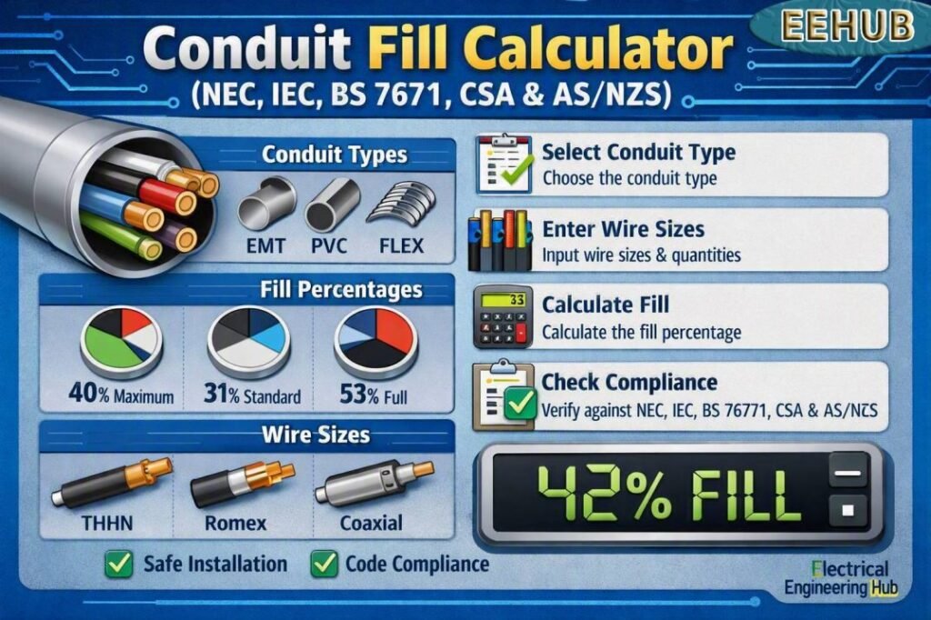
Table of Contents
Table of Contents
Conduit Fill Calculator (NEC, IEC, BS 7671, CSA and AS/NZS)
Work out how many conductors or cables can safely occupy a conduit, and get a recommended trade size, under the code convention you select. Switch between the North American percentage-fill method and the metric space-factor method used across IEC, BS 7671, and AS/NZS jurisdictions.
Step 1: Select Code Standard
Step 2: Add Conductors (AWG / kcmil, THHN-THWN-2 insulation)
Step 2: Add Cables (Outer Diameter, mm)
Results
| Trade / Nominal Size | Internal Area | Allowed Area at Max Fill | Fits? |
|---|
How to Use This Calculator
- Select the code standard you are designing under. NEC and CSA use the North American percentage-fill method with AWG and kcmil conductor sizing; IEC, BS 7671, and AS/NZS use the metric space-factor method based on the actual outer diameter of each cable.
- If you selected NEC or CSA, choose the conduit material (EMT, RMC, or PVC Schedule 40/80), since wall thickness changes the internal usable area for the same trade size.
- Add a row for every distinct conductor or cable size in the run, and enter how many of that size will be pulled together.
- Use “Add Conductor Size” or “Add Cable Size” to include additional sizes, or the remove button on a row to take one out.
- Select Calculate Conduit Fill. The tool totals the cross-sectional area of everything you entered, applies the correct maximum fill percentage for the total item count, and checks it against each standard trade or nominal conduit size.
- Review the recommended size, the fill percentage it results in, and the full size-by-size breakdown table to see how close the next size down would have been.
What Conduit Fill Means
Conduit fill is the proportion of a conduit’s internal cross-section that is taken up by the conductors or cables pulled through it. Every wiring code caps this proportion well below 100 percent, because conductors need clearance to be pulled in without damaging the insulation, and because a fully packed conduit traps heat that the conductors generate under load. Staying within the allowed fill also keeps future re-pulls or additions realistic.
Why the Allowed Percentage Changes With Conductor Count
A single conductor in a conduit is allowed a higher fill percentage than a bundle of three or more, because one conductor can move freely to dissipate heat and does not need room to shift past neighboring conductors during the pull. Two conductors sit in between. Three or more conductors are treated the most conservatively, since bundling multiple current-carrying conductors together concentrates heat and makes the pull itself more physically demanding. This is why every major standard uses a tiered allowance rather than one flat number.
Imperial vs. Metric Approach
NEC and CSA reference a fixed table of conductor areas by AWG or kcmil size and insulation type, cross-checked against a fixed table of conduit internal areas by trade size and material. IEC, BS 7671, and AS/NZS jurisdictions more commonly size conduit against the actual measured outer diameter of the cable being installed, since cable constructions and manufacturers vary more widely outside North America. Both approaches are trying to answer the same underlying question in a way that fits how conductors are specified in that region.
Common Mistakes to Avoid
Mixing conductor insulation types without re-checking the area table, forgetting to count a grounding or earth conductor as part of the total fill, choosing conduit size based on outside diameter alone rather than internal usable area, and reusing a fill calculation from a different conduit material are among the most frequent errors seen in the field. Re-verify the calculation whenever the conductor mix, insulation type, or conduit material changes.
Conduit Fill According to NEC, IEC, BS 7671, CSA and AS/NZS
| Standard | Common fill basis | Typical application | Main reference |
|---|---|---|---|
| NEC | 53% for 1 conductor, 31% for 2, 40% for 3+ | US installations | NEC Chapter 9, Table 1 |
| IEC 60364 | Based on installation conditions and cable/conduit selection | International installations | IEC 60364-5-52 |
| BS 7671 | Cable capacity and conduit sizing rules | UK installations | BS 7671 + On-Site Guide |
| CSA | Raceway/conduit area and conductor rules | Canada | CSA C22.1 |
| AS/NZS | Cable installation and wiring enclosure requirements | Australia & New Zealand | AS/NZS 3000 |
| General design check | Total cable area vs usable internal area | Preliminary sizing | Manufacturer/standard data |
A Conduit Fill Calculator helps determine whether the selected wires or cables can be installed safely inside a conduit, raceway, or similar wiring enclosure. Correct fill is important because overcrowding can make cable installation difficult, increase pulling tension, restrict heat dissipation, and create problems during future maintenance.
Although the calculation looks simple, the permitted fill percentage depends on the wiring standard being used. The NEC provides specific percentages, while IEC, BS 7671, CSA and AS/NZS systems require the designer to consider their respective cable, wiring-system and installation requirements.
What Is Conduit Fill?
Conduit fill is the percentage of the internal cross-sectional area of a conduit occupied by conductors or cables.
The basic calculation is:
Conduit Fill (%) = Total Area of Conductors ÷ Internal Area of Conduit × 100
For example, if the conductors occupy 0.80 in² and the conduit has an internal area of 2.00 in²:
Fill = 0.80 ÷ 2.00 × 100 = 40%
The result must then be compared with the applicable code limit.
A good Conduit Fill Calculator should therefore use the actual conductor diameter or area, the internal conduit diameter, the number of conductors and the applicable standard.
NEC Conduit Fill Rules
For US electrical installations, NEC Chapter 9, Table 1 establishes the basic raceway fill percentages.
| Number of conductors | Maximum fill |
|---|---|
| 1 conductor | 53% |
| 2 conductors | 31% |
| 3 or more conductors | 40% |
| Short nipples under specified conditions | Up to 60% |
The 40% limit is the value most commonly encountered when several insulated conductors are installed in EMT, PVC, RMC, IMC or another raceway.
For one conductor, the permitted area can reach 53% of the raceway's internal area. Read more in detail on Conduit Fill for 1 Conductor and the 53% rule here. For two conductors, the limit is 31% and read complete guide on conduit fill 2 conductors and 31 percent rule here. With three or more conductors, the limit is generally 40%. Read more in detail on NEC Conduit Fill for 3+ Conductors and 40% Rule here.
These percentages are not simply interchangeable. The number of conductors and the type of raceway must be checked against the applicable NEC provisions.
NEC Chapter 9 Table 1: Conduit Fill Percentage
NEC Chapter 9 Table 1 establishes the maximum allowable conductor fill percentages for raceways and provides the basis for conduit sizing under NEC requirements. For one conductor, the maximum fill is generally 53%; for two conductors, 31%; and for three or more conductors, 40%.
| Number of Conductors | Maximum Fill |
|---|---|
| 1 | 53% |
| 2 | 31% |
| 3 or More | 40% |
These limits are essential when using a conduit fill calculator to verify raceway capacity. For conductor areas and detailed NEC requirements, see our complete guide to NEC Chapter 9 Table 1.
Conduit Nipple Fill Rule NEC Under 24 Inches
The NEC provides a useful exception for short raceway sections, often called nipples. Under NEC Chapter 9, Table 1, Note 4, a conduit nipple 24 inches or less in length can use the conductor-fill allowance for two conductors, even when more than two conductors pass through it.
| Conduit Section | Maximum Fill |
|---|---|
| Up to 24 in. nipple | 31% |
| More than 24 in., 3+ conductors | 40% |
A Conduit Fill Calculator can help verify conductor area against the applicable allowance. For detailed calculations and examples, see our guide to Conduit Nipple Fill Rule NEC Under 24 Inches.
Wire Fill Chart for Conduit
A conduit fill chart helps determine how many conductors can safely fit inside EMT, PVC, or other raceways. The allowable fill depends on the number of conductors and the applicable electrical code.
| Conductors | Maximum Fill |
|---|---|
| 1 | 53% |
| 2 | 31% |
| 3 or more | 40% |
For conductor-specific dimensions and raceway capacities, see our detailed conduit fill chart guide, which includes common wire sizes, conduit types, and NEC-based fill limits. Always verify conductor insulation, raceway dimensions, and applicable code requirements before installation.
How to Calculate Conduit Fill
The calculation can be completed in four basic steps.
- Determine the internal area of the conduit.
- Determine the cross-sectional area of every conductor.
- Add the conductor areas together.
- Compare the total with the permitted raceway area.
For a circular conduit:
Internal Area = π × D² ÷ 4
where D is the actual internal diameter.
Suppose a conduit has an internal diameter of 1.049 inches.
Internal area:
π × 1.049² ÷ 4 = approximately 0.864 in²
If three or more conductors are installed, the 40% usable area is:
0.864 × 0.40 = 0.346 in²
If the combined conductor area is 0.30 in², the installation passes the basic fill-area calculation. Read our complete guide on how to calculate conduit fill here.
Conductor Area and Cable Diameter
Accurate conductor dimensions are essential. The nominal wire size alone does not always provide enough information for a precise calculation because insulation thickness, conductor construction and cable type can change the outside diameter.
For NEC calculations, conductor dimensions can be obtained from the applicable NEC tables or manufacturer data. Chapter 9 tables are especially useful for raceway dimensions, conductor properties and approximate areas.
For metric systems, cable manufacturers commonly provide the overall cable diameter. This value should be used when the installation rules require the outside dimensions of the cable.
Common inputs include:
- Conductor size
- Conductor material
- Insulation type
- Number of conductors
- Cable outside diameter
- Conduit internal diameter
- Conduit material
- Raceway type
- Applicable electrical standard
IEC Conduit Fill
IEC 60364-5-52 covers wiring systems and selection of wiring systems for electrical installations. Unlike the NEC approach, IEC-based design should not automatically be treated as having one universal fill percentage for every conduit and cable arrangement.
The installation method, cable construction, grouping, thermal conditions, mechanical protection and manufacturer instructions all affect the selection.
For an IEC installation, calculate the occupied cable area and compare the result with the applicable national requirements and product instructions.
This distinction matters when using a Conduit Fill Calculator across different countries. A calculation based on the NEC 40% rule should not automatically be presented as an IEC compliance result.
BS 7671 Conduit Fill
BS 7671 is the principal UK standard for electrical installations. Conduit selection involves more than simply calculating the percentage of empty space.
Designers should consider conductor capacity, installation method, grouping, thermal effects, cable pulling conditions and the guidance provided by BS 7671 and the relevant installation guides.
In practical UK work, conduit sizing tables and manufacturer data are often used to select an appropriate conduit size after identifying the conductor type and number.
For metric conduit systems, the actual internal diameter should be used rather than assuming that the nominal conduit size equals the available internal area.
CSA Conduit Fill in Canada
Canadian installations are governed primarily by the Canadian Electrical Code, CSA C22.1. Raceway and conductor requirements should be checked against the applicable edition and installation method.
The same basic engineering concept applies: determine the available raceway area, determine the occupied conductor area, and verify compliance with the applicable code tables and rules.
Canadian conduit installations may involve EMT, rigid conduit, PVC conduit and other raceway systems. Internal dimensions can differ between products with the same nominal trade size, so manufacturer specifications are useful for final verification.
AS/NZS Conduit Fill
AS/NZS 3000 is widely used for electrical installations in Australia and New Zealand. Conduit and wiring-system selection should be made according to the standard's requirements, the cable type and the installation conditions.
A simple percentage calculation can be useful for preliminary sizing, but it should not replace the applicable AS/NZS requirements.
Cable arrangement, mechanical protection, heat dissipation and ease of installation are important considerations. Where a manufacturer provides conduit capacity tables for a particular cable, conduit or fitting system, those tables should be checked before final selection.
Conduit Fill Example
Consider six insulated copper conductors with an individual cross-sectional area of 0.045 in².
Total conductor area:
6 × 0.045 = 0.270 in²
If the conduit has an internal area of 0.75 in²:
Fill = 0.270 ÷ 0.75 × 100 = 36%
Under the NEC's general three-or-more-conductor 40% limit, the area calculation would be within the basic fill allowance.
However, this does not by itself prove that the installation is code compliant. Ampacity adjustment, conductor insulation temperature, terminal ratings, conduit type and other applicable requirements must also be checked.
Conduit Fill vs Ampacity
Conduit fill and ampacity are different calculations.
Conduit fill determines whether the conductors physically fit within the permitted raceway area. Ampacity determines how much current the conductors can safely carry under the applicable conditions.
A conduit can pass the fill calculation while the conductors still require ampacity derating because several current-carrying conductors are installed together.
A complete design should therefore check:
- Raceway fill
- Conductor ampacity
- Ambient temperature
- Number of current-carrying conductors
- Voltage drop
- Conductor insulation rating
- Terminal temperature limitations
- Grounding and bonding requirements
Conduit Fill Derating Calculator
A Conduit Fill Derating Calculator helps determine allowable conductor fill when multiple current-carrying conductors share a raceway. NEC rules limit conduit fill based on conductor count, while ampacity may also require adjustment for conductor grouping.
| Conductors in Raceway | Maximum Fill |
|---|---|
| 1 | 53% |
| 2 | 31% |
| 3 or More | 40% |
For example, a raceway containing four or more conductors may be limited to 40% of its internal area. Use the Conduit Fill Derating Calculator to quickly check conductor capacity and avoid undersized raceways when applying NEC conduit-fill requirements.
Why Correct Conduit Sizing Matters
Oversized conduit can increase material and installation costs, while undersized conduit can create serious installation problems.
A correctly selected conduit provides enough space for the conductors without unnecessary oversizing. It also helps reduce pulling difficulty and makes future maintenance easier.
Conduit fill becomes especially important with larger conductors, multiple circuits, control wiring, solar installations, EV charging circuits and industrial power systems.
For long runs, the designer should also consider the number of bends and the manufacturer's pulling recommendations.
Conduit Fill Calculator Inputs
A practical calculator should allow users to enter the following information:
| Input | Purpose |
|---|---|
| Conduit type | Identifies the applicable raceway dimensions |
| Conduit size | Establishes nominal sizing |
| Internal diameter | Used for area calculation |
| Number of conductors | Determines applicable fill limit |
| Conductor size | Identifies conductor area |
| Cable diameter | Useful for multicore cables |
| Insulation type | Helps identify actual conductor dimensions |
| Standard | NEC, IEC, BS 7671, CSA or AS/NZS |
| Total conductor area | Determines occupied space |
| Maximum fill | Determines allowable occupied area |
Mixed Conductor Sizes in Conduit Fill
When a raceway contains different conductor sizes, each conductor must be included using its actual cross-sectional area. The NEC conduit-fill calculation is based on the total area occupied by all conductors, not simply the number of wires.
| Conductor Combination | Calculation Approach |
|---|---|
| Same size | Area × quantity |
| Mixed sizes | Add each conductor’s individual area |
| 3+ conductors | Maximum 40% fill |
A Conduit Fill Calculator makes mixed-size calculations easier by totaling conductor areas and comparing them with the allowable raceway area. For detailed examples and rounding rules, see this guide to Mixed Conductor Sizes in Conduit Fill.
Compact Conductor Conduit Fill
Compact conductors can affect conduit sizing because their stranded construction and smaller overall diameter may provide more usable space than standard conductors of the same ampacity. The actual conductor dimensions should always be taken from the manufacturer’s data.
| Conductor Type | Key Conduit-Fill Consideration |
|---|---|
| Compact stranded | Use actual outside diameter |
| Standard stranded | Use listed conductor area |
| Mixed conductors | Calculate each conductor separately |
A Conduit Fill Calculator can help determine the total conductor area and compare it with the permitted raceway fill percentage. For conductor-area calculations, examples, and sizing methods, see our detailed guide to Compact Conductor Conduit Fill.
Common Conduit Fill Mistakes
Several errors can lead to incorrect sizing.
First, do not use the outside diameter of the conduit when calculating its available internal area. The internal diameter is required.
Second, do not assume every standard uses the NEC 40% rule.
Third, do not calculate conductor area from wire gauge alone when accurate manufacturer dimensions are available.
Fourth, do not confuse conduit fill with ampacity. They address different design limitations.
Finally, do not ignore special rules for nipples, fittings, cable assemblies or particular wiring methods.
Conduit Fill for Solar and EV Installations
Modern electrical systems often contain multiple circuits in limited spaces. Solar PV systems may have DC conductors, AC circuits, grounding conductors and communication wiring, while EV installations can involve large conductors for high-current charging equipment.
A Conduit Fill Calculator can provide a fast first check before conduit is purchased or installed.
For example, a 48-amp Level 2 EV charger may require a dedicated circuit with relatively large conductors. The conduit must accommodate the conductors while also meeting ampacity, grounding and installation requirements.
Solar projects can require similar checks when multiple strings or larger feeder conductors share a raceway.
Final Conduit Sizing Checklist
Before approving a conduit size, verify:
- Conduit internal diameter
- Total conductor area
- Number of conductors
- Maximum permitted fill
- Conductor ampacity
- Adjustment and correction factors
- Voltage drop
- Raceway type
- Number of bends
- Pulling requirements
- Local electrical code
- Manufacturer installation instructions
A Conduit Fill Calculator is most useful when it is treated as a design aid rather than a replacement for the governing electrical code. NEC, IEC 60364, BS 7671, CSA C22.1 and AS/NZS 3000 have different structures and requirements, so the final conduit selection should always be verified against the standard applicable to the project.
Frequently Asked Questions
What is the maximum conduit fill under NEC?
For three or more conductors, the general NEC raceway fill limit is 40% of the internal raceway area. The limit is 31% for two conductors and 53% for one conductor, subject to the applicable NEC rules and exceptions.
How is conduit fill calculated?
Divide the total cross-sectional area of the conductors by the internal cross-sectional area of the conduit and multiply by 100. The resulting percentage is compared with the permitted fill for the applicable wiring standard.
Can I use the NEC 40% rule for IEC or BS 7671 installations?
Not automatically. IEC and BS 7671 installations must be evaluated using their applicable requirements. The NEC 40% value is a US code rule and should not be treated as a universal international requirement.
Does conduit fill affect cable ampacity?
Conduit fill itself is not an ampacity calculation. However, multiple current-carrying conductors in the same raceway can require ampacity adjustment or derating under the applicable electrical standard.
What information is needed for a conduit fill calculation?
You normally need the conduit internal diameter, number of conductors, conductor or cable outside diameter or cross-sectional area, conductor type and the electrical standard governing the installation. Manufacturer data should be used where precise dimensions are required.
Get new guides in your feed. Follow Electrical Insights on LinkedIn for new electrical standards guides, calculators and design tips from Azad Circuit Hub.
ConduitFillCalculator, #ConduitFill, #ElectricalEngineering, #NEC, #IEC, #BS7671, #CSA, #ASNZS, #ConduitSizing, #WireSizing
Conduit Fill Calculator – Global Standards (NEC, IEC & More)

Conduit Fill Calculator for NEC, IEC, BS 7671, CSA & AS/NZS standards. Calculate conduit capacity, wire fill, cable sizing, and allowable fill percentage accurately.
Price Currency: USD
Operating System: All
Application Category: UtilitiesApplication
