
The Complete Guide to Home Wiring & BS 7671 (UK)
A safe home electrical installation needs the right cables, protective devices, earthing arrangements, and testing. Whether you are buying a house, renovating a kitchen, adding sockets, or upgrading a consumer unit, understanding the UK wiring system helps you make better decisions and spot potential hazards.
This Guide to Home Wiring explains domestic electrical systems in the United Kingdom, including cable colours, ring final circuits, circuit breakers, RCDs, RCBOS, electric showers, cooker circuits, garage supplies, and electrical inspection reports. It also explains how BS 7671 and Part P apply to common domestic electrical work.
The aim is practical: help homeowners understand what a compliant installation should look like, what an electrician needs to check, and when professional testing or building control notification is required.
Complete Guide to Home Wiring & BS 7671 (UK)
| Topic | UK Requirement or Practice | Why It Matters |
|---|---|---|
| Main wiring standard | BS 7671, subject to the applicable edition and amendments | Sets requirements for electrical installation safety |
| Building regulations | Part P in England and Wales | Covers electrical safety in domestic premises |
| Typical supply | 230 V single-phase for many homes | Determines circuit design and equipment selection |
| Lighting circuits | Commonly 1.0 mm² or 1.5 mm² copper cable | Final size depends on design conditions |
| Socket circuits | Commonly 2.5 mm² copper cable | Often used for ring final circuits |
| Cooker circuits | Commonly 6 mm² or larger | Depends on load, cable route, and installation method |
| Shower circuits | Often 6 mm², 10 mm², or larger | Depends on shower rating and cable conditions |
| Shock protection | Earthing, bonding, and appropriate RCD protection | Reduces the risk of electric shock |
| Overcurrent protection | MCB, RCBO, or suitable fuse | Protects conductors against overloads and faults |
| Installation verification | Inspection, testing, and certification | Confirms that the installation meets relevant requirements |
These are typical examples, not universal design rules. The correct cable size and protective device must be selected using the actual installation conditions and applicable requirements of BS 7671.
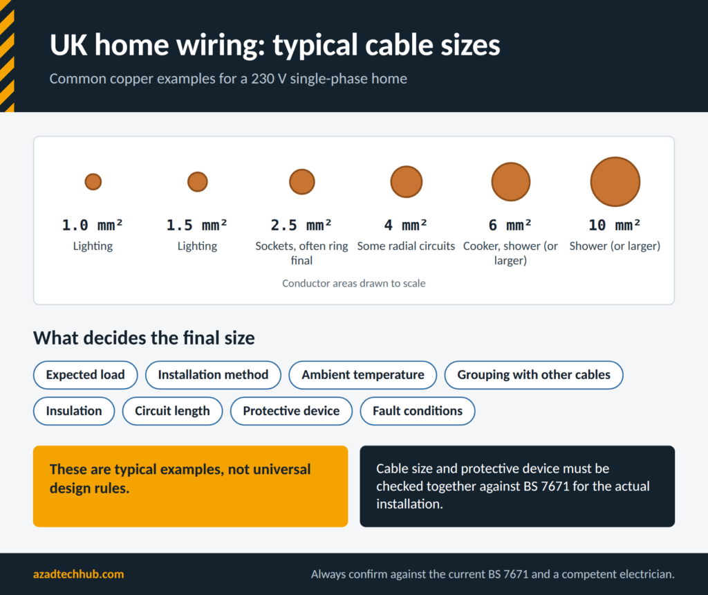
Table of Contents
Table of Contents
What Is BS 7671 and Why Does It Matter?
BS 7671 is the UK standard commonly known as the IET Wiring Regulations. It sets requirements for the design, erection, inspection, and testing of electrical installations. It applies to domestic properties as well as commercial and industrial buildings.
The standard covers conductor sizing, protection against electric shock, earthing, overcurrent protection, voltage drop, isolation, and verification. It also addresses installations that include equipment such as solar PV systems, battery storage, and electric vehicle charging points.
BS 7671 is not a substitute for the Building Regulations. In England and Wales, Part P addresses electrical safety in domestic premises. The applicable requirements and notification routes depend on the type of work and the relevant jurisdiction.
A compliant installation must do more than use the right cable. The designer or electrician must consider the complete circuit, including the protective device, cable route, accessories, earthing system, and expected load.
Who Is Responsible for Domestic Electrical Safety?
Homeowners should understand the condition of their installation and arrange repairs when defects appear. Landlords have additional legal duties, including electrical safety inspection requirements in England under the applicable private rented sector regulations.
A competent electrician should assess work that requires electrical design, installation, or verification. For major work, ask for the appropriate electrical installation certificate or minor electrical installation works certificate. Where required, obtain the relevant building regulations compliance documentation as well.
Main Components of a UK Domestic Electrical Installation
Most homes receive electricity through a service cable and meter before it reaches the consumer unit. From there, separate circuits supply lighting, sockets, cooking equipment, showers, heating, and other loads.
| Component | Main Function |
|---|---|
| Electricity meter | Measures energy consumption |
| Main switch | Isolates the installation or consumer unit |
| Consumer unit | Distributes electricity to individual circuits |
| MCB | Protects against overloads and short circuits |
| RCD | Provides additional protection against certain earth leakage currents |
| RCBO | Combines residual-current and overcurrent protection |
| Main earthing terminal | Connects the installation’s earthing conductors |
| Main protective bonding | Connects specified extraneous-conductive-parts to the earthing system |
| Circuit conductors | Carry current to lights, sockets, and appliances |
A modern consumer unit may contain separate RCBOs for each circuit. This can reduce the number of circuits affected when a fault occurs, although the actual level of protection depends on the design.
How Electricity Flows Through a Home
In a typical single-phase installation, the live conductor supplies energy to the load, while the neutral conductor provides the normal return path. The circuit protective conductor, usually called the CPC or earth conductor, provides a protective path for fault current.
Under normal conditions, the CPC should not carry load current. If a fault connects a live conductor to an exposed conductive part, the earthing arrangement and protective device must operate as intended to reduce the risk of electric shock.
Never assume that a green-and-yellow conductor is safe to touch. An incorrectly wired or faulty installation can leave protective conductors at a dangerous voltage.
Understanding Consumer Units, MCBs, RCDs, and RCBOs
The consumer unit is one of the most important parts of a domestic installation. It distributes the supply and contains devices designed to protect circuits.
| Device | Protection Provided | Important Limitation |
|---|---|---|
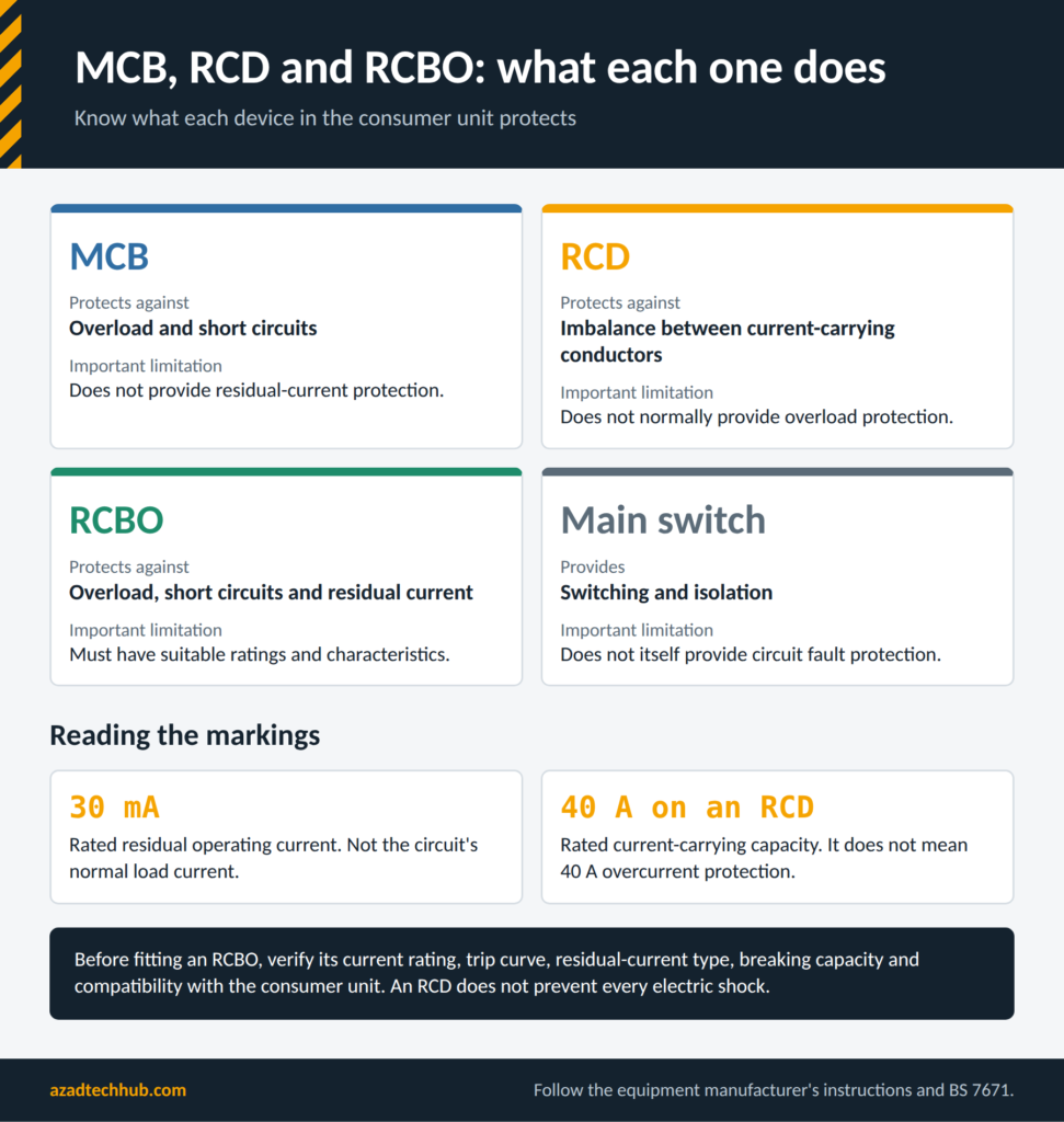
| MCB | Overload and short-circuit protection | Does not provide residual-current protection |
| RCD | Detects an imbalance between current-carrying conductors | Does not normally provide overload protection |
| RCBO | Overload, short-circuit, and residual-current protection | Must have suitable ratings and characteristics |
| Main switch | Switching and isolation | Does not itself provide circuit fault protection |
RCD protection is particularly important because certain earth leakage faults may not produce enough current to operate an ordinary MCB quickly. However, an RCD does not prevent every electric shock and must not replace proper earthing or safe working practices.
The type of RCD also matters. Some electronic equipment can produce residual-current waveforms that require a particular RCD type. Selection should follow the equipment manufacturer’s instructions and the applicable requirements of BS 7671. For detail comparison follow our guide on types of RCDs.
Reading the Circuit Schedule
The circuit schedule is normally located inside or near the consumer unit. It identifies the circuits, their protective devices, and often the rooms or equipment they supply.
An electrician should verify that each label matches the actual circuit. Incorrect labels can delay fault-finding and cause someone to isolate the wrong circuit during maintenance.
Do not remove the consumer unit cover to investigate wiring. Dangerous live parts may be exposed even when an individual circuit breaker is switched off.
Ring Final Circuits and Radial Socket Circuits
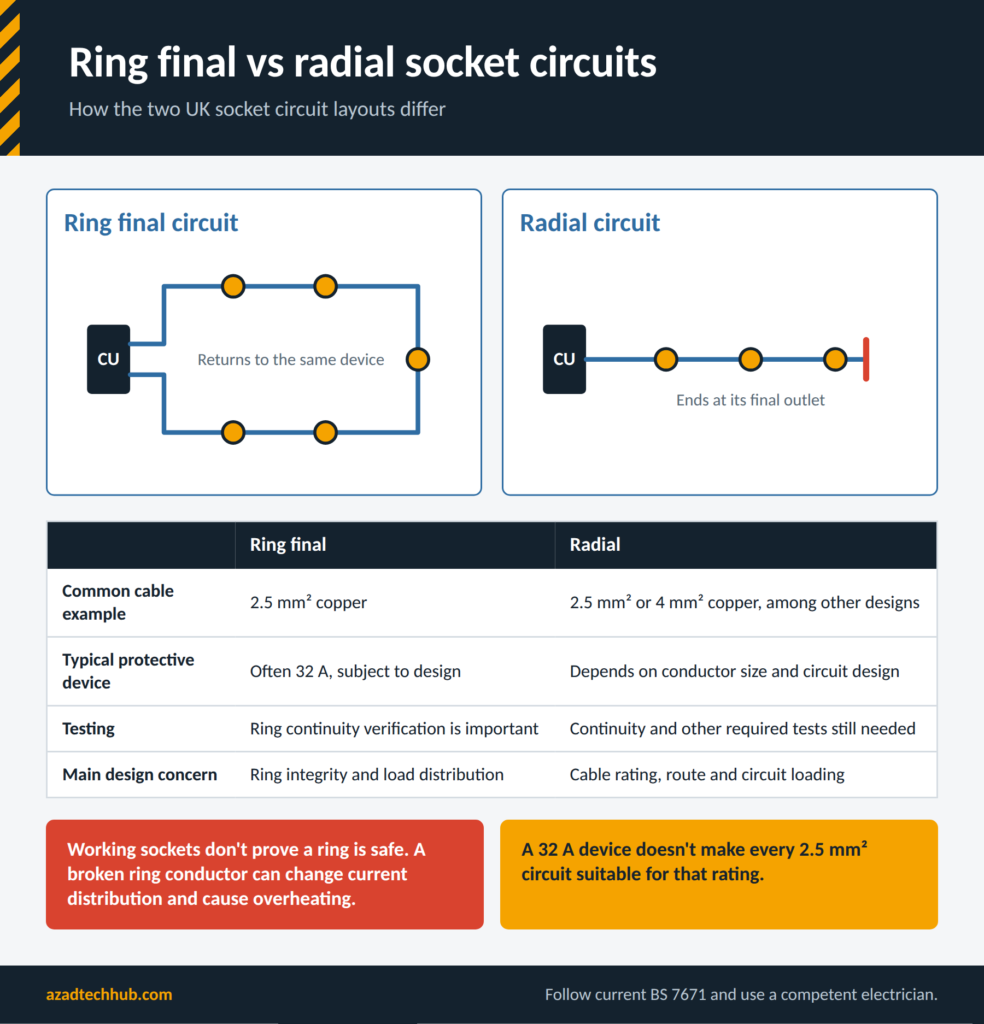
UK homes commonly use both ring final circuits and radial circuits. A ring final circuit leaves the consumer unit, supplies the socket outlets, and returns to the same protective device. A radial circuit ends at its final outlet rather than returning to the origin.
| Feature | Ring Final Circuit | Radial Circuit |
|---|---|---|
| Cable arrangement | Outgoing and returning legs form a ring | One route from the origin to the final outlet |
| Common cable example | 2.5 mm² copper | 2.5 mm² or 4 mm² copper, among other designs |
| Typical protective device | Often 32 A, subject to design | Depends on conductor size and circuit design |
| Testing requirement | Ring continuity verification is important | Continuity and other required tests are still necessary |
| Main design concern | Correct ring integrity and load distribution | Cable rating, route, and circuit loading |
A ring circuit must not be assumed to be safe simply because its sockets work. A broken ring conductor can alter current distribution and create overheating risks under some conditions.
The cable size and breaker rating must be checked together. A 32 A protective device does not automatically make every circuit using 2.5 mm² cable suitable for that rating.
Cable Colours Used in UK Home Wiring
The UK harmonised cable colours use brown for live, blue for neutral, and green-and-yellow for the circuit protective conductor in modern fixed wiring.
| Conductor Function | Modern Colour | Older UK Colour |
|---|---|---|
| Single-phase live | Brown | Red |
| Single-phase neutral | Blue | Black |
| Protective earth | Green and yellow | Green or green and yellow, depending on age |
| Three-phase L1 | Brown | Red |
| Three-phase L2 | Black | Yellow |
| Three-phase L3 | Grey | Blue |
| Three-phase neutral | Blue | Black |
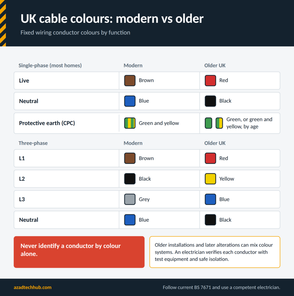
Older installations may use different colours, and alterations can introduce mixed wiring systems. Never identify a conductor by colour alone. An electrician must verify conductor function with appropriate test equipment and safe isolation procedures.
Cable Selection, Voltage Drop, and Circuit Protection
Cable sizing is a technical design task. The correct conductor depends on the expected load, installation method, ambient temperature, grouping, insulation, circuit length, protective device, and fault conditions.
For example, a cable installed in free air may dissipate heat more effectively than the same cable enclosed in thermal insulation. Several cables grouped together can also run hotter. These factors affect the current-carrying capacity.
Basic Current Calculations
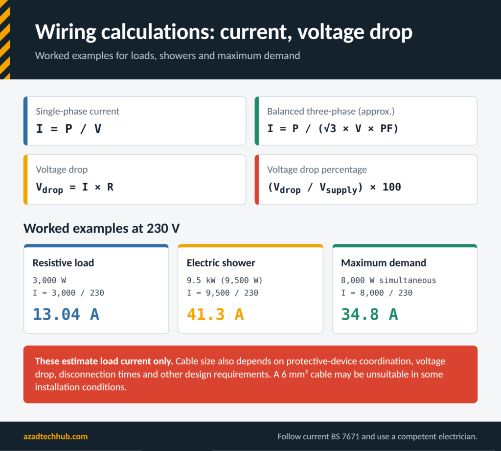
For a single-phase load, a simplified current calculation is:
Current (A) = Power (W) / Voltage (V)
For a 3,000 W resistive load supplied at 230 V:
Current = 3,000 / 230 = 13.04 A
For a balanced three-phase load, a common approximation is:
Current (A) = Power (W) / (√3 × Voltage (V) × Power Factor)
For motors, input power, efficiency, and power factor must be considered when calculating current from a rated mechanical output.
These equations estimate load current. They do not determine the final cable size by themselves. Cable selection must also account for protective-device coordination, voltage drop, disconnection times, and other applicable design requirements.
Voltage Drop Calculation
For a simplified single-phase circuit:
Voltage Drop (V) = Current (A) × Circuit Resistance (Ω)
The percentage voltage drop is:
Voltage Drop (%) = [Voltage Drop (V) / Supply Voltage (V)] × 100
In practice, the designer should use suitable conductor resistance or impedance data and the relevant BS 7671 calculation method. Cable length, conductor temperature, and the circuit arrangement all affect the result.
Earthing, Bonding, and Protection Against Electric Shock
Earthing and bonding serve different purposes. Earthing connects exposed conductive parts to the installation’s protective earthing system. Main protective bonding connects specified extraneous-conductive-parts, such as qualifying incoming metallic services, to the main earthing terminal.
The required arrangements depend on the supply type and building conditions. A property may use a TN-S, TN-C-S, or TT earthing arrangement, among other possible configurations.
An electrician must verify the earthing system before making changes to the consumer unit or adding new circuits. Never install an earth electrode or connect bonding conductors based only on a visual guess.
For a TT system, residual-current protection often plays a central role in meeting the required fault protection conditions. The design must take account of electrode resistance, protective-device characteristics, and the applicable disconnection requirements.
Planning a Home Rewire or Electrical Upgrade
A full rewire is an opportunity to correct old wiring, add circuits, improve protection, and prepare a property for future loads. Before work starts, create a circuit schedule and identify the appliances that need dedicated supplies.
A practical planning sequence includes:
- Inspect the existing installation and review any available electrical certificates.
- List fixed appliances, lighting points, socket locations, and outdoor supplies.
- Identify high-load equipment, including showers, cookers, heat pumps, and EV chargers.
- Confirm the supply characteristics, earthing arrangement, and service capacity.
- Design cable routes and protective devices using the applicable regulations.
- Plan testing, certification, and any required building regulations notification.
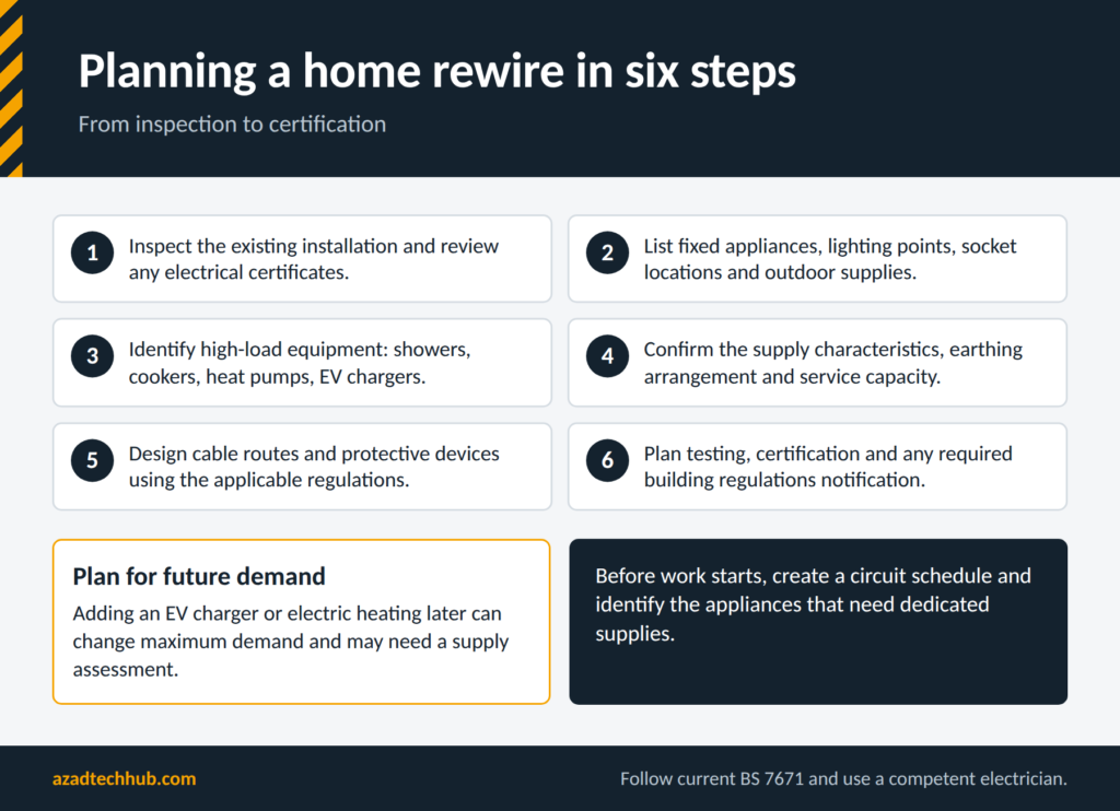
It is also sensible to plan for future demand. Adding an EV charger or electric heating later can change the maximum demand and may require a supply assessment.
Ring Circuit Continuity and Installation Testing
Checking the Integrity of a Socket Ring
A ring final circuit needs appropriate continuity testing to confirm that the line, neutral, and CPC conductors form the intended paths. This is a job for a competent person with suitable instruments and safe isolation procedures.
The testing process involves verifying the relevant conductors, investigating unexpected readings, and confirming that the completed circuit meets the required criteria. A continuity reading alone cannot prove that an installation is fully safe. Insulation resistance, polarity, protective-conductor continuity, and other applicable tests may also be required.
Understanding Protective Device Markings
Labels on an RCD or RCBO can show its rated current, residual operating current, device type, and other characteristics. These markings help an electrician check whether the device is suitable for the circuit and the connected equipment.
For example, a 30 mA marking refers to the rated residual operating current, not the circuit’s normal load current. A 40 A marking on an RCD refers to its rated current-carrying capacity and does not mean that it provides 40 A overcurrent protection.
When a Combined Protective Device Is Useful
An RCBO combines residual-current and overcurrent protection in one device. Using individual RCBOs can help isolate a fault to one circuit instead of allowing an RCD serving several circuits to disconnect them all.
However, an RCBO is not automatically suitable for every circuit. Its current rating, trip curve, residual-current type, breaking capacity, and compatibility with the consumer unit must be verified.
Changes in the 18th Edition Wiring Regulations
BS 7671 has been updated through amendments to address changes in electrical equipment, technology, and installation practice. Amendment 3:2024 included provisions relating to power electronic equipment and prosumer electrical installations, including systems that generate, store, or manage electricity.
For homeowners, this is particularly relevant when considering solar PV, battery storage, and other equipment that can supply or control power within an installation. Such systems need suitable protection, isolation, labelling, and coordination with the existing electrical supply.
Do not assume that every existing home needs immediate replacement because an amendment has been published. The applicable requirements depend on the work being carried out, the relevant edition and amendments, and any specific legal obligations. Before publication or electrical work, verify the current BS 7671 status and transition arrangements through the IET and BSI, as newer amendments may supersede earlier guidance.
How Many Socket Outlets Can a UK Circuit Supply?
There is no single universal maximum number of socket outlets that can be applied to every ring final or radial circuit. Circuit design depends on expected demand, cable characteristics, protective devices, the floor area and use of the premises, and the applicable design guidance.
A ring circuit with many sockets may be suitable where expected demand is modest, while a smaller number of outlets serving heaters or other high-load equipment may require a separate circuit. The number of sockets alone does not establish circuit safety.
A designer should assess likely simultaneous loads and consider whether dedicated circuits are needed for fixed appliances.
Electric Shower and Cooker Cable Sizing
Electric showers and cookers can draw substantial current, so their circuits require careful design. The shower’s rated power, supply voltage, cable length, installation method, insulation, and protective-device requirements all affect the selection.
For example, a 9.5 kW shower at 230 V draws approximately:
Current = 9,500 / 230 = 41.3 A
This calculation shows why cable size cannot be selected by appearance alone. A 6 mm² cable may be unsuitable in some installation conditions, even when it appears commonly used elsewhere. Use our AC cable size calculator to estimate the accurate cable size.
Cooker circuits need the same careful approach. The designer must assess the appliance rating, diversity where permitted, cable route, voltage drop, and protective-device coordination. Never replace a breaker with a higher-rated one simply to stop nuisance tripping.
DIY Electrical Work and Part P
Part P of the Building Regulations applies to electrical safety in domestic premises in England and Wales. Some work is notifiable, while other work may be completed without building control notification if the applicable requirements are met.
The rules differ by jurisdiction. Scotland and Northern Ireland have their own building standards or regulatory arrangements, so homeowners should not assume that the English and Welsh notification rules apply throughout the UK.
Replacing an accessory is not the same as adding a new circuit or altering a consumer unit. Even where a task is not notifiable, the installation must still be safe and comply with applicable requirements.
Before starting work, check the current rules for the property location and use a competent electrician when the task involves uncertain wiring, protective devices, new circuits, or work requiring inspection and testing.
Fused Spurs, Lighting Switches, and Cable Identification
A fused connection unit can supply a fixed appliance from a suitable circuit, with the fuse providing protection appropriate to the connected equipment and cable. The circuit design must account for the load, cable rating, and required isolation arrangements.
Two-way lighting allows one light to be controlled from two locations, such as the top and bottom of a staircase. The switching arrangement uses appropriate conductors between the switches, and conductor identification must remain clear.
Modern brown-and-blue cable colours should not be confused with older red-and-black wiring. If an older circuit is extended, the electrician must identify the conductors, use appropriate accessories and identification, and verify the completed work through testing.
Finding a Tripped RCD or Repeated Electrical Fault
An RCD may trip because of an appliance fault, damaged cable, moisture, or cumulative leakage from several connected devices. Repeated tripping should be treated as a warning rather than a nuisance to bypass.
A homeowner can note which circuits have lost power and whether the problem started after an appliance was connected. If an appliance can be unplugged safely without touching damaged equipment, doing so may help provide useful information for the electrician.
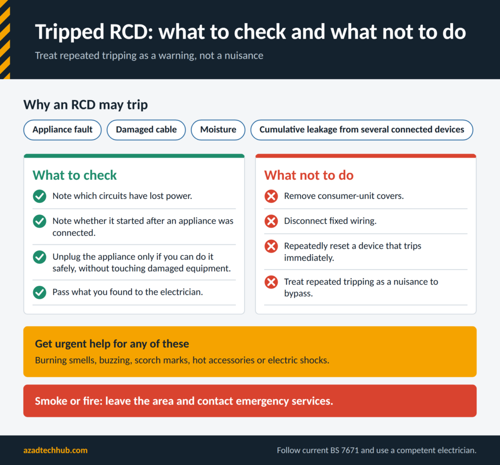
Do not remove consumer-unit covers, disconnect fixed wiring, or repeatedly reset a device that trips immediately. Burning smells, buzzing, scorch marks, hot accessories, or electric shocks require urgent attention. If there is smoke or a fire, leave the area and contact emergency services.
Electrical Installation Condition Reports and C2 Codes
An Electrical Installation Condition Report (EICR) records the condition of an existing installation based on inspection and testing. It identifies defects and observations that need assessment.
A C2 code means a potentially dangerous condition that requires urgent remedial action. It does not mean that every circuit in the property must automatically be replaced. The electrician should explain the specific defect, its risk, and the appropriate remedy.
| EICR Code | General Meaning |
|---|---|
| C1 | Danger present; immediate remedial action required |
| C2 | Potentially dangerous; urgent remedial action required |
| C3 | Improvement recommended |
| FI | Further investigation required without delay |
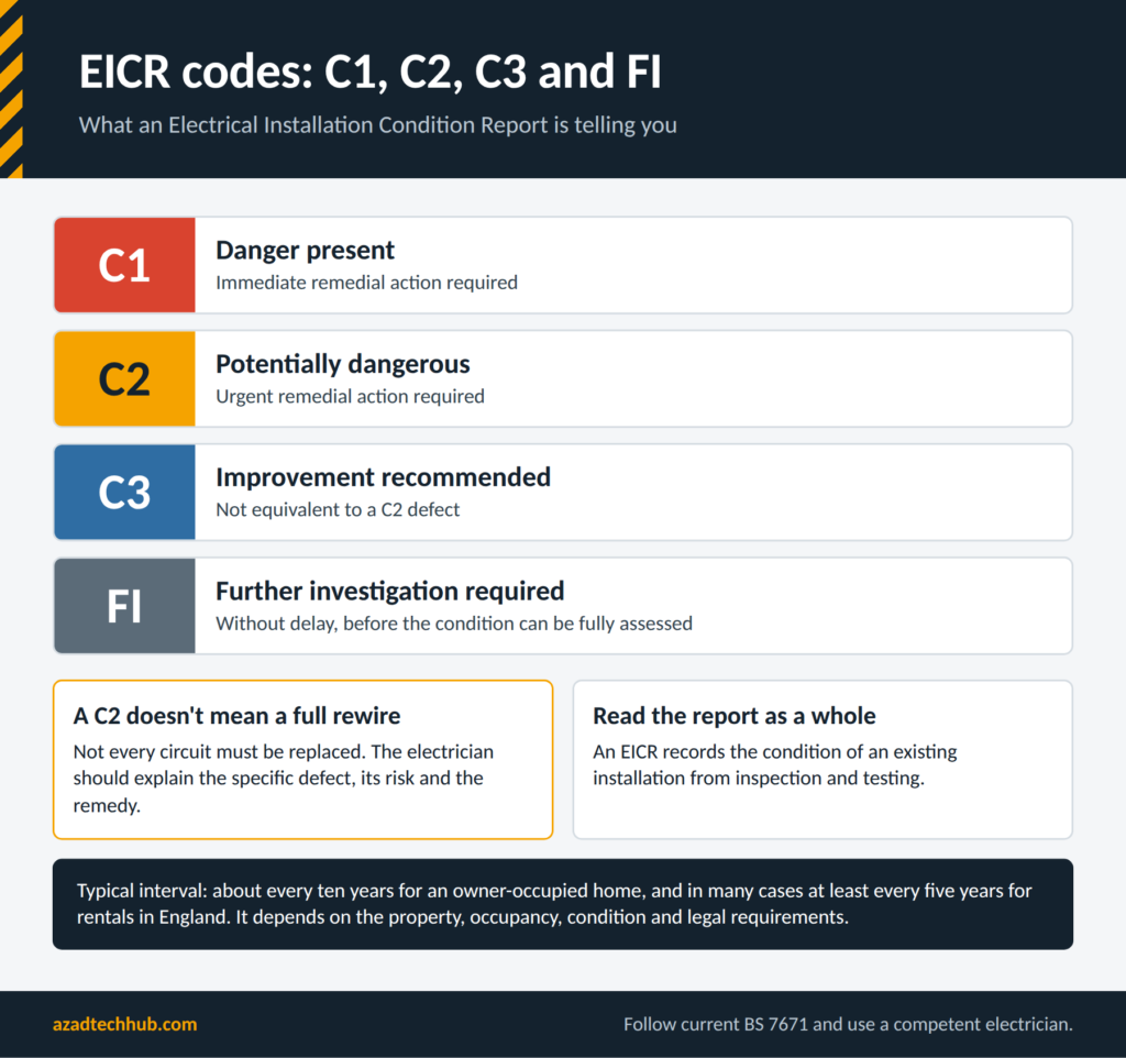
The report should be read as a whole. A C3 observation is not equivalent to a C2 defect, and an FI observation indicates that further investigation is needed before the condition can be fully assessed.
Garage Supplies, SWA Cable, and Outdoor Wiring
A detached garage or garden workshop may need a dedicated supply. The design should account for the load, cable route, mechanical protection, voltage drop, earthing arrangements, and the protective devices at both ends where applicable.
Steel wire armoured (SWA) cable is commonly used for outdoor and underground supplies because its construction provides mechanical protection. However, the cable must still be selected and installed correctly, with suitable glands, terminations, and protection.
The choice of earthing arrangement for an outbuilding is important. A designer must consider the existing supply system, exported earth arrangements, any local electrode requirements, and the possibility of simultaneous contact with conductive parts. Do not connect a garage consumer unit by copying a diagram without first establishing the installation conditions.
Calculating Maximum Demand in a Domestic Property
Maximum demand is the expected highest load on an installation under the conditions considered in the design. It is not necessarily the sum of every appliance’s nameplate current because not all loads operate at full power at the same time.
A simplified starting point is:
Maximum Demand (A) = Estimated Simultaneous Load (W) / Supply Voltage (V)
For example, if the estimated simultaneous single-phase load is 8,000 W at 230 V:
Maximum Demand = 8,000 / 230 = 34.8 A
This is only a simplified estimate. A proper assessment should consider applicable diversity guidance, load profiles, fixed heating, cooking appliances, EV charging, heat pumps, and any equipment with high starting currents. The supply capacity and protective arrangements must then be checked by a competent designer.
Practical Home Wiring Safety Checklist
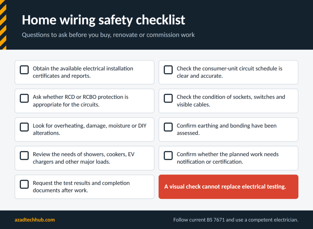
Before buying a property, planning a renovation, or commissioning electrical work, use this checklist to identify questions that need professional attention.
- Obtain the available electrical installation certificates and reports.
- Check whether the consumer-unit circuit schedule is clear and accurate.
- Ask whether RCD or RCBO protection is appropriate for the circuits.
- Check the condition of sockets, switches, and visible cables.
- Look for signs of overheating, damage, moisture, or DIY alterations.
- Confirm that earthing and bonding have been assessed.
- Review the electrical requirements of showers, cookers, EV chargers, and other major loads.
- Confirm whether the planned work requires notification or certification.
- Request the correct test results and completion documents after work.
A visual check cannot replace electrical testing. Hidden cable damage, poor connections, inadequate fault protection, and incorrect polarity may not be apparent from the outside.
Frequently Asked Questions
1. What are the current UK regulations for home wiring?
BS 7671 is the principal wiring standard used for electrical installations in the UK. Building regulations also apply, including Part P in England and Wales. The applicable edition, amendments, and notification requirements should be checked before work begins.
2. Can I do my own electrical work at home in the UK?
Some minor tasks may be possible, but the legal and notification requirements depend on the work and the UK jurisdiction. New circuits, consumer-unit work, and other complex alterations should be planned and completed by a competent electrician. All electrical work must be safe and comply with applicable requirements.
3. What cable size is used for home wiring in the UK?
Common examples include 1.0 mm² or 1.5 mm² cable for some lighting circuits and 2.5 mm² cable for many socket circuits. These sizes are not universal. Cable length, installation method, insulation, load, and protective-device ratings must all be considered.
4. Do UK homes need RCD protection?
RCD protection is required for many domestic circuits and situations under the applicable wiring requirements. The exact requirements depend on the circuit, installation conditions, and protective arrangement. An electrician should check the existing installation rather than assuming that an older consumer unit meets current requirements.
5. How often should a house have an electrical inspection?
There is no single inspection interval that suits every property. A common recommendation is an EICR approximately every ten years for an owner-occupied home, while rental properties in England generally have specific inspection requirements, including at least every five years in many cases. The appropriate interval depends on the property, occupancy, installation condition, and applicable legal requirements.
Final Thoughts
A safe domestic electrical system depends on correct design, suitable protective devices, reliable earthing, and proper testing. Understanding the main parts of an installation helps homeowners ask better questions, recognise warning signs, and plan electrical upgrades with fewer surprises.
Use this Guide to Home Wiring as a starting point when reviewing a property or planning improvements. For actual electrical work, confirm the current BS 7671 requirements, check the building regulations that apply to your location, and engage a competent electrician to design, install, inspect, and test the system.
From an electrical engineering perspective, a circuit should never be judged by cable colour, breaker rating, or appearance alone. The complete installation must be assessed as a system, with protection and conductor sizing verified against the real operating conditions.
Get new guides in your feed. Follow Electrical Insights on LinkedIn for new electrical standards guides, calculators and design tips from Azad Circuit Hub.


