
Differential Protection Relay Setting Calculator | IEC 60255-187 and IEEE C37.91
Differential protection is one of the fastest and most reliable protection methods used in electrical power systems. It protects transformers, generators, motors, busbars, and transmission lines by comparing the current entering and leaving the protected zone. A properly configured Differential Protection Relay Setting Calculator helps engineers determine accurate pickup values, percentage bias, and operating characteristics while reducing unnecessary relay trips.
Using a Differential Protection Relay Setting Calculator saves time during relay commissioning and improves system reliability. It also minimizes human error during calculations and ensures that relay settings comply with project specifications and applicable standards.
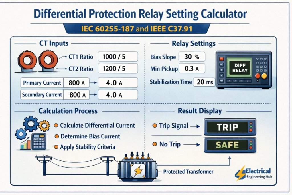
Table of Contents
Table of Contents
Differential Protection Relay Setting Calculator
Differential Protection Relay Setting Calculator
Percentage-bias (restrained) differential protection setting tool for two-winding transformers, generators, motors and busbar zones, built around IEC 60255-187 and IEEE C37.91 setting practice.
System & CT Data
Enter the protected equipment rating and the current transformers on each side of the differential zone.
Setting Results
Reference current, CT mismatch, bias characteristic and recommended pickup values.
Optional: Minimum CT Knee-Point Voltage Check
Show / hide ▾A quick stability check to confirm the CT knee-point voltage is adequate to prevent saturation during a heavy external through-fault, which is the main cause of unwanted differential trips.
Typical Bias Characteristic Settings by Equipment
| Equipment | Is1 (% In) | Slope 1 | Breakpoint Is2 | Slope 2 | Unrestrained high-set | Harmonic restraint |
|---|---|---|---|---|---|---|
| Two-winding transformer | 20 – 30% | 20 – 30% | 1.5 – 2 × In | 60 – 80% | 6 – 10 × In | 2nd harmonic (inrush), 5th harmonic (overflux) |
| Generator | 5 – 10% | 10 – 20% | 1.25 – 1.5 × In | 40 – 60% | Usually not applied | Not normally required |
| Large motor | 20 – 30% | 20 – 25% | 1.5 – 2 × In | 60 – 70% | 6 – 8 × In | Only if fed via starting transformer |
| Busbar zone (low-Z biased) | 20 – 40% | 30 – 50% | 2 – 3 × In | 70 – 90% | Not normally applied | Not applicable |
How to Use This Calculator
- Select the protected equipment type at the top – transformer, generator, motor or busbar zone. This loads typical starting values for the bias settings, which you can adjust freely.
- Enter the equipment rated power and the voltage on each side of the protection zone (for a busbar zone, enter the same voltage on both sides and use the feeder CT ratios as Side 1 and Side 2).
- Enter the CT ratio (primary/secondary amps), connection and accuracy class for each side, exactly as marked on the CT nameplate.
- For a transformer, select the vector group so the note reflects how phase-shift compensation is handled; this has no effect on the numeric results since it is applied internally by the relay.
- Review or adjust the bias characteristic settings – minimum pickup, both slopes, the breakpoint and the unrestrained high-set – then press “Calculate Relay Settings”.
- Check the CT ratio mismatch indicator: a green result means the mismatch is within a range that software ratio-matching in a numerical relay comfortably absorbs; amber or red means the CT ratios or the pickup setting should be reviewed.
- Use the bias characteristic chart to see where the calculated operating point sits relative to the trip curve, and open the optional CT knee-point check if you have through-fault and CT winding data available.
This guide explains the calculation process, relay settings, influencing factors, practical examples, and best practices for achieving dependable differential protection.
What Is a Differential Protection Relay?
A differential protection relay compares the current entering a protected electrical zone with the current leaving it.
Under normal operating conditions, both currents are nearly equal. If an internal fault occurs, the difference between these currents increases rapidly. Once the differential current exceeds the relay pickup setting, the relay sends a trip signal to isolate the faulty equipment.
This protection principle provides high sensitivity for internal faults while remaining stable during external faults.
What Is a Differential Protection Relay Setting Calculator?
A Differential Protection Relay Setting Calculator is an engineering tool used to determine the correct operating parameters for differential protection relays.
The calculator typically evaluates:
- Differential current
- Restraining current
- Pickup current
- Percentage bias (slope)
- CT ratio compensation
- Relay operating point
- Stability during through faults
These calculations help engineers configure protection relays accurately before testing and commissioning.
Why Accurate Relay Settings Matter
Incorrect differential relay settings can create serious protection problems.
| Incorrect Setting | Possible Result |
|---|---|
| Pickup too low | Unwanted relay trips |
| Pickup too high | Internal faults may not clear quickly |
| Wrong CT ratio | False differential current |
| Poor slope selection | Relay instability during external faults |
| Incorrect compensation | Reduced protection sensitivity |
Accurate calculations improve equipment protection and reduce downtime.
Basic Differential Protection Operating Principle
The relay continuously measures current from both sides of the protected equipment.
Under healthy conditions:
Current In = Current Out
During an internal fault:
Current In ≠ Current Out
The relay calculates:
Differential Current (Id) = |I1 − I2|
Restraining Current (Ir)
Ir = (|I1| + |I2|) ÷ 2
The relay operates when the differential current exceeds the pickup threshold and satisfies the selected percentage restraint characteristic.
Main Parameters Used in Differential Relay Settings
A Differential Protection Relay Setting Calculator requires several input values before generating relay settings.
| Parameter | Description |
|---|---|
| CT Primary Ratio | Primary current transformer rating |
| CT Secondary Rating | Usually 1 A or 5 A |
| Transformer Rating | Power rating of equipment |
| Rated Voltage | Primary and secondary voltage |
| Pickup Setting | Minimum differential current |
| Bias Setting | Percentage restraint slope |
| Vector Group | Transformer phase shift compensation |
| CT Accuracy Class | Determines measurement performance |
These values ensure accurate relay coordination.
Differential Protection Relay Setting Calculation Example
Consider a power transformer with the following data.
| Parameter | Value |
|---|---|
| Transformer Rating | 10 MVA |
| Voltage | 33/11 kV |
| CT Ratio (HV) | 200/1 |
| CT Ratio (LV) | 600/1 |
| Pickup Current | 0.3 A |
| Bias Slope | 30% |
Suppose the relay measures:
- HV current = 0.90 A
- LV compensated current = 0.50 A
Differential Current
Id = |0.90 − 0.50|
Id = 0.40 A
Restraining Current
Ir = (0.90 + 0.50) ÷ 2
Ir = 0.70 A
Operating Limit
0.30 + (30% × 0.70)
= 0.30 + 0.21
= 0.51 A
Since the differential current is below the operating threshold, the relay remains stable and does not trip.
A Differential Protection Relay Setting Calculator performs these calculations automatically, reducing engineering effort and improving accuracy.
IEC Standard for Differential Protection
The IEC Standard for Differential Protection provides a structured framework for relay performance, stability, sensitivity, and operating characteristics in power-system protection. IEC 60255-187 is particularly relevant to differential protection relay functions and helps engineers evaluate relay behavior under internal and external fault conditions.
| Parameter | IEC-based consideration |
|---|---|
| Relay characteristic | Differential current and restraint |
| Stability | Security during external faults |
| Sensitivity | Reliable internal-fault detection |
| Testing | Functional and performance verification |
When configuring protection settings, engineers can use a Differential Protection Relay Setting Calculator to estimate pickup and restraint values before validating them against the applicable relay manufacturer’s instructions and system study.
For a deeper explanation of IEC Standard for Differential Protection, including practical setting considerations and calculation guidance, see the dedicated spoke article.
High Impedance Differential Protection Calculation
High impedance differential schemes require careful calculation of relay voltage, CT performance, and stabilizing resistance to remain secure during external faults. The High Impedance Differential Protection Calculation typically considers the maximum through-fault current, CT secondary resistance, lead resistance, and relay burden. The calculated voltage must remain within the relay and CT limits while providing sufficient sensitivity for internal faults.
| Parameter | Purpose |
|---|---|
| Through-fault current | Determines CT secondary fault current |
| CT resistance | Accounts for CT winding voltage drop |
| Lead resistance | Includes wiring voltage drop |
| Stabilizing resistor | Prevents unwanted relay operation |
For broader relay-setting checks, use the Differential Protection Relay Setting Calculator to evaluate pickup and related protection parameters. For the complete methodology, equations, and worked examples, see our detailed guide on high impedance differential protection calculations.
Important Relay Settings
Pickup Current
The pickup current determines the minimum differential current required for relay operation.
Typical values range between:
- 20% to 40% of relay rated current
- Based on CT accuracy
- Equipment rating
- Protection philosophy
Percentage Bias
The percentage bias prevents false tripping caused by CT saturation or measurement errors.
Typical settings include:
| Equipment | Typical Bias |
|---|---|
| Power Transformer | 20–40% |
| Generator | 15–35% |
| Busbar | 20–50% |
| Large Motor | 20–40% |
Harmonic Restraint
Transformer energization produces high magnetizing inrush current.
Modern relays use second harmonic restraint to prevent unwanted operation during transformer energization.
CT Ratio Compensation
Primary and secondary CT ratios rarely match perfectly.
Differential relays compensate for ratio differences to maintain measurement accuracy.
Transformer Differential Protection Relay
A transformer differential protection relay protects power transformers by comparing the current entering and leaving the transformer. Under normal load or external faults, the currents remain balanced after accounting for the transformer ratio and phase shift. An internal transformer fault creates a differential current, causing the relay to trip the circuit breaker quickly.
| Parameter | Typical consideration |
|---|---|
| Protection zone | Transformer and connected equipment |
| Operating principle | Current differential |
| Main setting | Differential pickup |
| Key factors | CT ratio, vector group, inrush current |
| Common standard | IEC 60255-187 |
For a detailed explanation of transformer protection principles, settings, restraint characteristics, and practical examples, see our guide to transformer differential protection relay.
Correct CT matching, percentage restraint, harmonic blocking, and pickup settings are essential for dependable operation. When calculating relay parameters, a Differential Protection Relay Setting Calculator can help verify the required values before commissioning.
Busbar Differential Protection Setting Calculation
A Busbar Differential Protection Setting calculation determines the relay operating threshold needed to detect internal busbar faults while remaining stable during external faults and CT saturation. The setting depends on CT ratios, maximum through-fault current, relay characteristics, and the selected differential protection scheme.
| Parameter | Purpose |
|---|---|
| CT ratio | Determines current seen by the relay |
| Maximum through-fault current | Checks stability during external faults |
| Differential pickup | Defines the minimum operating current |
| Bias/slope setting | Improves security against CT saturation |
For practical protection studies, engineers can use a Differential Protection Relay Setting Calculator to estimate pickup and bias values before validating them against the relay manufacturer’s manual, CT performance, and applicable protection standards.
For the detailed calculation method, formulas, and worked examples, see the complete guide on Busbar Differential Protection Setting.
Factors Affecting Differential Relay Settings
Several engineering factors influence relay configuration.
| Factor | Impact |
|---|---|
| CT saturation | May produce false differential current |
| Transformer tap changer | Changes current ratio |
| Magnetizing inrush | Requires harmonic blocking |
| Through fault current | Tests relay stability |
| Vector group | Requires phase angle compensation |
| CT polarity | Incorrect polarity causes relay malfunction |
| Relay accuracy | Improves protection performance |
All these parameters should be verified before finalizing settings.
CT Polarity for Differential Protection
Correct CT Polarity for Differential Protection is essential for reliable differential protection because the relay must distinguish between load or external fault current and an internal fault. CT secondary connections are arranged so that currents entering and leaving the protected zone balance during normal operation and external faults.
| Condition | Expected Differential Current | Protection Response |
|---|---|---|
| Normal load | Near zero | No trip |
| External fault | Low after compensation | Stable |
| Internal fault | High | Trip |
Incorrect CT polarity can cause circulating currents to appear as differential current, potentially producing unwanted trips. When checking relay settings, polarity should therefore be verified alongside CT ratios, vector compensation, and pickup values.
The Differential Protection Relay Setting Calculator can help determine suitable operating parameters, while a dedicated guide on CT polarity in differential protection explains polarity markings, secondary wiring, testing, and common connection errors.
Transformer Differential Protection Testing
Transformer differential protection testing verifies that the relay correctly detects internal transformer faults while remaining stable during external faults and normal operating conditions. Testing should confirm CT polarity, ratio compensation, phase-angle compensation, restraint characteristics, and trip logic before energization.
| Test | What to Verify | Typical Check |
|---|---|---|
| CT ratio test | Correct CT ratio | Compare nameplate and relay settings |
| CT polarity test | Correct current direction | Primary/secondary polarity confirmation |
| Secondary injection | Relay pickup and timing | Inject operating and restraint currents |
| Trip test | Breaker operation | Verify relay-to-trip circuit |
| Stability test | No unwanted operation | Simulate external fault conditions |
The Differential Protection Relay Setting Calculator can help establish preliminary differential, bias, and pickup settings, but these values should be validated through site-specific testing. During Transformer Differential Protection Testing, test results should be documented and compared with the approved protection study and manufacturer requirements.
Applications of Differential Protection
Differential protection is widely used throughout modern power systems.
| Equipment | Protection Purpose |
|---|---|
| Power Transformers | Internal winding faults |
| Busbars | Bus differential protection |
| Generators | Stator winding protection |
| Large Motors | Internal winding faults |
| Reactors | Internal faults |
| Transmission Lines | Line current comparison |
The Differential Protection Relay Setting Calculator can be adapted for different equipment by entering the appropriate system parameters.
Common Mistakes During Relay Setting
Many commissioning issues result from avoidable configuration errors.
- Incorrect CT ratio selection
- Wrong CT polarity
- Ignoring transformer vector group
- Very low pickup settings
- Excessive bias values
- Missing harmonic restraint
- Incorrect secondary current values
- Poor relay coordination with upstream protection
Careful verification helps eliminate these problems before system energization.
Best Practices for Relay Coordination
Follow these recommendations for reliable differential protection.
- Verify all CT ratios before commissioning.
- Confirm CT polarity through testing.
- Match relay settings with equipment ratings.
- Use correct transformer vector group compensation.
- Perform secondary injection testing.
- Check harmonic restraint settings.
- Validate relay stability during external fault simulations.
- Document all protection settings for future maintenance.
These practices improve protection reliability and reduce commissioning delays.
Advantages of Using a Differential Protection Relay Setting Calculator
Using a dedicated calculation tool offers several benefits.
| Benefit | Description |
|---|---|
| Faster calculations | Saves engineering time |
| Improved accuracy | Reduces manual calculation errors |
| Better coordination | Supports proper relay grading |
| Easy commissioning | Simplifies relay configuration |
| Reliable protection | Enhances fault detection |
| Consistent settings | Standardizes engineering practice |
The calculator also helps engineers compare multiple operating scenarios before finalizing protection settings.
Conclusion
A Differential Protection Relay Setting Calculator is an essential engineering tool for configuring reliable differential protection in transformers, generators, motors, busbars, and other critical electrical equipment. It simplifies the calculation of differential current, restraining current, pickup values, and percentage bias while reducing the possibility of manual errors.
Accurate relay settings improve fault detection, maintain stability during external faults, and enhance overall power system reliability. When combined with proper CT selection, vector group compensation, harmonic restraint, and thorough commissioning tests, a Differential Protection Relay Setting Calculator helps engineers achieve dependable protection that safeguards valuable electrical assets and minimizes unexpected outages.
Get new guides in your feed. Follow Electrical Insights on LinkedIn for new electrical standards guides, calculators and design tips from Azad Circuit Hub.
DifferentialProtectionRelaySettingCalculator, #DifferentialProtection, #ProtectionRelay, #PowerSystemProtection, #RelaySettings, #ElectricalEngineering, #IEC60255187, #IEEEC3791, #TransformerProtection, #PowerEngineers
Differential Protection Relay Setting Calculator | IEC 60255-187 and IEEE C37.91
Differential Protection Relay Setting Calculator helps engineers calculate pickup current, slope, restraint settings, and relay parameters according to IEC 60255-187 and IEEE C37.91 standards for transformers, generators, and busbar protection.
Price Currency: USD
Operating System: Web Browser
Application Category: UtilitiesApplication
