
Cable Bending Radius: IEC Standard, Formula & Minimum Radius Chart
Cable bending radius is one of the most important factors in electrical installation, cable management, and long-term system reliability. Whether you are installing low-voltage wiring, armoured cable, fiber optic cable, or high-voltage power lines, understanding the correct Cable Bending Radius can prevent insulation damage, conductor stress, and early cable failure.
Many electricians, engineers, and contractors ignore bend radius requirements during installation. This often causes overheating, signal loss, or insulation cracks. International standards like IEC, BS 7671, NEC, and VDE provide clear rules for safe cable bending.
In this guide, you will learn the standard formula, minimum bend radius chart, cable tray bending requirements, and practical rules for different cable types.
Cable Bending Radius Chart
| Cable Type | Typical Minimum Bend Radius | Common Reference |
|---|---|---|
| PVC insulated single-core cable | 6 × cable diameter | Manufacturer/IEC practice |
| XLPE insulated single-core cable | 8 × cable diameter | Manufacturer/IEC practice |
| XLPE multicore power cable | 12 × cable diameter | Manufacturer/IEC practice |
| PVC multicore power cable | 10 × cable diameter | Manufacturer/IEC practice |
| Armored power cable | 12 × cable diameter | Manufacturer/installation standard |
| Flexible control cable | 6–8 × cable diameter | Manufacturer specification |
| Flexible instrumentation cable | 6–10 × cable diameter | Manufacturer specification |
| Cat 5e/Cat 6 data cable | 4 × cable diameter | Cabling practice |
| Fiber optic cable | 10–20 × cable diameter | Manufacturer specification |
| Coaxial cable | 6–10 × cable diameter | Manufacturer specification |
For detailed cable bending charts visit our guide here Cable Bending Radius Chart by Cable Size
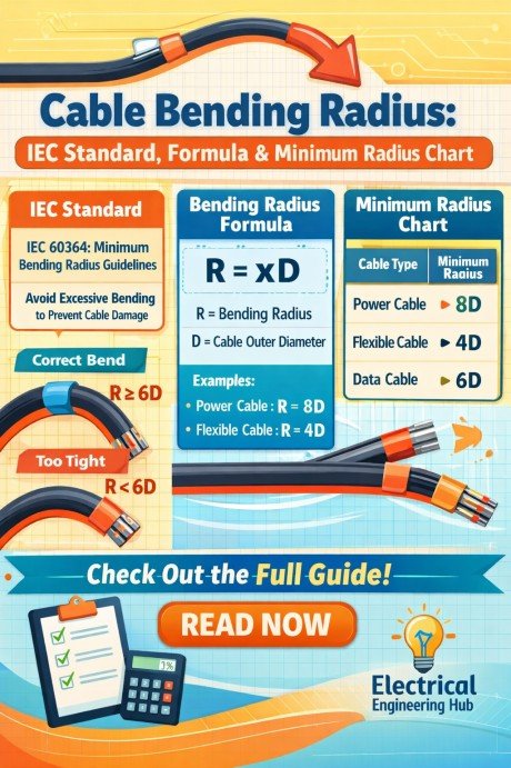
Table of Contents
Table of Contents
What Is Cable Bending Radius?
Cable Bending Radius is the minimum radius a cable can be bent without causing damage to its conductor, insulation, shielding, or outer sheath. It is usually measured from the inner curve of the bend.
In simple words, it tells you how tight a cable can be bent safely.
For example, if a cable has an outer diameter of 20 mm and the minimum bend radius is 8 times its diameter, the bend radius will be:
8 × 20 = 160 mm
This means the cable should not be bent tighter than 160 mm.
The bend radius depends on:
- Cable diameter
- Cable construction
- Insulation type
- Number of cores
- Voltage rating
- Installation conditions
A smaller bend than the recommended value may cause:
| Issue | Impact |
|---|---|
| Insulation cracks | Short circuit risk |
| Conductor deformation | Higher resistance |
| Shield damage | EMI problems |
| Fiber breakage | Signal loss |
| Mechanical stress | Reduced cable life |
How to Measure Bending Radius of Cable
To understand how to measure bending radius of cable, measure from the cable’s centerline to the center of the curve—not from the outer edge. The measured radius should meet the manufacturer’s minimum requirement and the applicable installation standard. This is an important part of maintaining the correct Cable Bending Radius during installation.
| Measurement | Method | Purpose |
|---|---|---|
| Cable diameter (D) | Measure the outside diameter with calipers | Establish reference size |
| Bend radius (R) | Measure from cable centerline to curve center | Determine actual radius |
| Bend diameter | Measure across the cable centerline | Equals 2 × R |
| Minimum radius | Compare R with manufacturer/standard value | Confirm safe installation |
Cable Bending Radius Measurement Formula
If the bend diameter is known, calculate:
R = Bend Diameter ÷ 2
For example, if the centerline bend diameter is 400 mm, the radius is 200 mm. Always compare the result with the cable datasheet, because required minimum radius varies with cable construction, voltage rating, conductor size, insulation, and whether the cable is being bent during installation or after installation.
Why Minimum Bend Radius Matters
Minimum bend radius is not just a recommendation. It is a critical installation requirement.
When a cable bends, the outer side stretches while the inner side compresses. Excessive bending can permanently damage internal layers.
Here is why it matters:
Protects conductor integrity
Tight bends can deform copper or aluminum conductors. This increases resistance and heating.
Prevents insulation damage
PVC, XLPE, and rubber insulation can crack under excessive stress.
Maintains electrical performance
Proper bend radius ensures current carrying capacity remains stable.
Extends service life
A correctly bent cable can operate safely for decades.
Avoids installation failures
Many cable faults are caused by mechanical damage during pulling and routing.
In industrial plants, substations, and underground systems, bend radius compliance is essential for safety and maintenance.
Cable Bending Radius Formula
The standard formula for Cable Bending Radius is:
Minimum Bend Radius = Cable Diameter × Multiplier
Where:
- Cable Diameter = overall outside diameter (OD)
- Multiplier = standard factor based on cable type
Example Calculation
Suppose:
- Cable OD = 25 mm
- Standard multiplier = 12
Calculation:
Minimum Bend Radius = 25 × 12
Minimum Bend Radius = 300 mm
This means the cable must not be bent below 300 mm.
Common Multipliers
| Cable Type | Multiplier |
|---|---|
| Fixed power cable | 6D |
| Flexible cable | 4D |
| Armoured cable | 12D |
| Fiber optic cable | 10D to 20D |
| High voltage cable | 15D |
D means outer diameter.
This formula is widely used for electrical cable bend radius calculations.
Minimum Bending Radius by Standard (IEC, BS 7671, VDE, NEC)
Different international standards define cable bend radius requirements.
Cable Bending Radius IEC Standard
IEC 60502 and IEC 60364 are commonly used for power cable installation. Lets explore IEC 60502 here.
IEC 60502 Bending Radius of Cables
IEC 60502 specifies the minimum bend radius for cables used in low- and medium-voltage power installations to avoid insulation damage and conductor stress. The standard defines different bend radius for cables based on construction type and voltage grade. For multicore cables, the minimum radius is generally 12× the overall cable diameter, while single-core cables may require 15× to 20× depending on shielding and armoring.
| Cable Type | Minimum Bending Radius |
|---|---|
| Multicore Cable | 12 × D |
| Single-Core Unarmoured | 15 × D |
| Single-Core Armoured | 20 × D |
You can follow the complete guide here IEC 60502 Bending Radius of Cables, which includes detailed recommendations.
Cable Bending Radius BS 7671
BS 7671 aligns closely with IEC requirements and is used in the UK.
General recommendation:
- Thermoplastic cables: 6D
- Thermosetting cables: 8D
- Armoured cables: 12D to 15D
Cable Bending Radius VDE Standard
German VDE standards are stricter for industrial applications.
Typical values:
- Control cables: 7.5D
- Flexible cables: 4D
- Heavy-duty power cables: 12D
Cable Bending Radius NEC Standard
The National Electrical Code in the US refers to manufacturer guidelines and conduit fill standards.
NEC often uses:
- Shielded cables: 12D
- Medium voltage cables: 8D to 15D
Following these standards improves compliance and inspection approval.
NEC Cable Bend Radius Chart
The NEC does not provide one universal bend-radius value for every cable. Requirements depend on the wiring method and cable type. For many cables, NEC rules point to the applicable product standard or manufacturer’s instructions.
| NEC Cable / Wiring Method | Typical Minimum Bend Radius | Relevant NEC Consideration |
|---|---|---|
| NM-B cable | 5 × cable diameter* | NEC 334.24 |
| Type SE cable | 5 × cable diameter* | NEC 338.24 |
| Type MC cable | 7 × cable diameter* | NEC 330.24 |
| Type AC cable | 5 × cable diameter* | NEC 320.24 |
| Type UF cable | 5 × cable diameter* | NEC 340.24 |
| Type TC cable | Manufacturer-specific | NEC 336.24 |
| Type RMC | 6 × outside diameter | NEC 344.24 |
| Type IMC | 6 × outside diameter | NEC 342.24 |
| EMT | 6 × outside diameter | NEC 358.26 |
| PVC Schedule 40/80 | 3 × outside diameter | NEC 352.24 |
| Flexible metal conduit | Manufacturer-specific | NEC 360.24 |
| Large single-conductor cables | Manufacturer-specific | See NEC 300.34 and applicable product standard |
*For certain cable sizes and constructions, the applicable NEC section contains additional conditions and exceptions. Always verify the exact cable type and size.
Quick Calculation
Minimum Bend Radius = Cable Outside Diameter × Required Multiplier
Example: For a 1-inch-diameter MC cable with a 7× requirement:
1 × 7 = 7 inches minimum bend radius
Important: Don’t apply these values blindly to every installation. NEC Article 300.34, the individual cable article, applicable UL/ANSI product standard, and the manufacturer’s installation instructions can affect the required bending radius. For large conductors, pulling tension and sidewall pressure are also important.
Cable Bend Radius — CEC
The Canadian Electrical Code (CEC) generally requires wiring methods to be installed without damage and with bends that respect the applicable product standard/manufacturer requirements. There is not one universal bend-radius multiplier for every cable type.
| Cable / Wiring Method | Minimum Bend Radius | CEC Consideration |
|---|---|---|
| NMD90 cable | Follow manufacturer requirements | Avoid sharp bends or cable damage |
| AC90 armored cable | Follow cable manufacturer/product standard | Maintain required bending radius |
| TECK90 cable | Follow manufacturer specifications | Bend radius varies by cable construction |
| RW90 single conductor | Follow manufacturer specifications | Consider insulation and conductor construction |
| Flexible cord | Follow manufacturer requirements | Do not exceed the cord’s rated flexibility |
| Communications cable | Follow manufacturer/installation standard | Excessive bending can affect performance |
| Large power cable | Manufacturer-specific | Radius becomes especially important during pulling |
| Armoured power cable | Manufacturer-specific | Account for armor and conductor construction |
Quick Calculation
If the cable manufacturer specifies a 12× outside-diameter minimum bend radius:
Minimum Bend Radius = Cable Outside Diameter × 12
For a 40 mm cable:
40 × 12 = 480 mm minimum bend radius
Important: For CEC-compliant design, don’t apply a generic “6×, 8×, or 12×” rule without checking the cable’s construction and manufacturer datasheet. For a specific CEC installation, the applicable CEC section, cable standard, and manufacturer’s bending requirement should be checked.
SWA Cable Bending Radius Chart
For Steel Wire Armoured (SWA) cables, the minimum bending radius depends on whether the cable is single-core or multicore, its voltage rating, and the cable manufacturer’s construction.
| SWA Cable Type | Typical Minimum Bend Radius | Typical Application |
|---|---|---|
| 1-core SWA | 8 × cable overall diameter | DC, solar, and power distribution |
| 2-core SWA | 8 × cable overall diameter | Single-phase power |
| 3-core SWA | 8 × cable overall diameter | Three-phase power |
| 4-core SWA | 8 × cable overall diameter | Three-phase + neutral |
| 4-core + earth SWA | 8 × cable overall diameter | Distribution systems |
| LV XLPE/SWA/PVC | 8 × cable diameter | Industrial and building power |
| MV XLPE/SWA cable | 12–15 × cable diameter | Medium-voltage distribution |
SWA Cable Bend Radius Formula
Minimum Bend Radius = Cable Overall Diameter × Manufacturer’s Bend-Radius Factor
For example, if a 50 mm SWA cable requires an 8× minimum radius:
50 × 8 = 400 mm
So, the cable should be bent around a curve with a minimum radius of 400 mm.
Important: These are typical design values, not a universal SWA rule. The exact minimum bend radius should always be taken from the cable manufacturer’s datasheet and applicable cable standard. Also distinguish between minimum bending radius during installation and the radius permitted for permanent/fixed installation, as they can differ.
500, 600 & 750 kcmil Cable Bend Radius
| Cable Size | Typical Minimum Bend Radius* | Example if Cable OD = 1.25 in |
|---|---|---|
| 500 kcmil | 8 × cable OD | 10 in |
| 600 kcmil | 8 × cable OD | 10 in |
| 750 kcmil | 8 × cable OD | 10 in |
*The 8× factor is only an example planning value, not a universal NEC requirement. For large conductors, the actual minimum bend radius depends on the cable construction, insulation, conductor type, number of conductors, and manufacturer.
Formula:
Minimum Bend Radius = Cable Outside Diameter × Required Bend-Radius Factor
For example, if a 750 kcmil cable has an actual outside diameter of 1.50 in and its manufacturer specifies 8× OD:
1.50 × 8 = 12 inches minimum bend radius
For NEC installations, use the manufacturer’s published bend radius and the applicable NEC requirements rather than selecting a radius based solely on kcmil size.
Minimum Bend Radius by Cable Type
Cable design changes the bending requirement significantly.
Below are common cable categories.
1. Armoured Cable Bending Radius (SWA/AWA)
Armoured cables contain steel wire armour (SWA) or aluminum wire armour (AWA). These layers make the cable stronger but less flexible.
Typical minimum radius:
| Cable Type | Radius |
|---|---|
| 2-core SWA | 8D |
| 3-core SWA | 12D |
| Multi-core SWA | 12D to 15D |
Example:
A 30 mm SWA cable:
12 × 30 = 360 mm
Important factors:
- Armour stiffness
- Pulling tension
- Installation temperature
Improper bending can damage the armour and reduce earth continuity. Follow the complete guide on armoured cable bending radius here. If you find any difficulty in calculations, you can try our free tool armoured cable bending radius calculator.
2. Fiber Optic Cable
Fiber optic cables are highly sensitive to bending. Tight bends cause attenuation and signal loss.
Fiber bend radius types:
| Condition | Radius |
|---|---|
| During installation | 20D |
| After installation | 10D |
Example:
OD = 10 mm
During pulling:
20 × 10 = 200 mm
Permanent:
10 × 10 = 100 mm
Exceeding these limits can cause microbending losses.
Fiber cable bend radius is critical in telecom systems and data centers. You can try our free tool to calculate the bending radius for fiber optic cables.
Fiber Optic Cable Bend Radius Chart
A fiber optic cable bend radius chart shows the minimum radius a fiber cable can safely bend without causing excessive attenuation, fiber damage, or permanent deformation. The required radius depends on cable construction and whether the cable is under tension during installation. As a practical guide, many fiber optic cables require a larger radius while being pulled and a smaller radius after installation.
| Fiber Cable Type | Typical Minimum Bend Radius – Installation | Typical Minimum Bend Radius – Installed |
|---|---|---|
| Indoor tight-buffered | 10–20 × cable OD | 5–10 × cable OD |
| Outdoor loose-tube | 20 × cable OD | 10 × cable OD |
| Armored fiber optic | 20 × cable OD | 10 × cable OD |
| ADSS fiber cable | 20 × cable OD | 10 × cable OD |
| Fiber patch cord | 10–15 × cable OD | 5–10 × cable OD |
For example, if a fiber cable has a 10 mm outside diameter and the manufacturer’s requirement is 20× during installation, the minimum radius is 200 mm. Unlike general Cable Bending Radius calculations, fiber optic cables are particularly sensitive to tight bends because excessive curvature can increase optical loss or permanently damage the fiber.
Fiber Optic Cable Bend Radius Calculation
Minimum bend radius = Cable outside diameter × Bend-radius multiplier
| Cable OD | 10× Radius | 15× Radius | 20× Radius |
|---|---|---|---|
| 5 mm | 50 mm | 75 mm | 100 mm |
| 8 mm | 80 mm | 120 mm | 160 mm |
| 10 mm | 100 mm | 150 mm | 200 mm |
| 12 mm | 120 mm | 180 mm | 240 mm |
| 15 mm | 150 mm | 225 mm | 300 mm |
3. Medium & High Voltage Cable
Medium voltage and high voltage cables use thicker insulation and shielding.
Typical values:
| Voltage Level | Radius |
|---|---|
| 11kV cable | 12D |
| 33kV cable | 15D |
| 66kV cable | 18D |
| 132kV cable | 20D |
These cables require larger turning spaces because of insulation thickness. Read more in detail here High Voltage Cable Bending Radius.
Underground cable routing should always consider trench bend radius. Follow the complete guide on 11KV cable bending radius here. We have also published a dedicated tool for HV cable bending radius to calculate the exact bending for your next cable laying. You can access the HV cable bending radius calculator here.
4. Flexible vs. Fixed Installation Cable
Flexible and fixed cables have different mechanical properties.
| Type | Bend Radius |
|---|---|
| Flexible cable | 4D to 6D |
| Fixed cable | 6D to 8D |
Flexible cables are designed for repeated movement.
Examples:
- Welding cables
- Control cables
- Robotic cables
Fixed cables are used in permanent installations.
Examples:
- Building wiring
- Distribution boards
- Cable trays
Choosing the wrong bend radius affects cable durability.
5. Coaxial Cable Bend Radius: Minimum Radius Chart
The coaxial cable bend radius is the smallest curve a coaxial cable should make without damaging its dielectric, shield, or center conductor. Always follow the manufacturer’s datasheet because the allowable radius varies by cable construction and whether the bend is permanent or temporary. As a general Cable Bending Radius rule, avoid sharp bends and kinks, particularly with high-frequency RF and communications cables.
| Coaxial Cable Type | Typical Minimum Bend Radius* | Common Application |
|---|---|---|
| RG-6 | 3–4 × cable OD | TV, satellite, broadband |
| RG-11 | 5–7 × cable OD | Long-distance CATV |
| RG-58 | 5 × cable OD | RF, antennas, test equipment |
| RG-59 | 5–7 × cable OD | CCTV, video |
| LMR-400 | 4 × cable OD | RF, wireless systems |
| Semi-rigid coax | Manufacturer-specific | RF/microwave |
*Typical values only; use the cable manufacturer’s specified minimum.
How to Calculate Coaxial Cable Bend Radius
Use:
Minimum Bend Radius = Cable Outside Diameter × Bend-Radius Factor
For example, a 10 mm coaxial cable with a recommended factor of 5 requires a minimum bend radius of 50 mm. Do not confuse bend radius with bend diameter; the bend diameter is twice the radius. Maintaining the correct radius helps preserve impedance, reduce signal loss, and prevent permanent deformation.
Battery Cable Bend Radius Chart
Battery cables are typically flexible, but the minimum bend radius depends on cable construction, conductor size, insulation, and manufacturer specifications. For planning purposes, the following values are commonly used:
| Battery Cable Type | Typical Minimum Bend Radius | Application |
|---|---|---|
| Flexible battery cable | 4–6 × cable OD | Automotive, RV, small battery systems |
| Fine-strand welding/battery cable | 3–5 × cable OD | Inverters, batteries, DC systems |
| Flexible copper power cable | 4–6 × cable OD | Solar and battery banks |
| XLPE battery/power cable | 6–8 × cable OD | High-current DC systems |
| Armored battery/power cable | 8–12 × cable OD | Industrial installations |
| Large battery cable | 6–10 × cable OD | UPS and energy-storage systems |
Formula:
Minimum Bend Radius = Cable Outside Diameter × Bend-Radius Factor
For example, if a battery cable is 20 mm in diameter and the specified bend radius is 5×:
20 × 5 = 100 mm minimum bend radius
Important for Battery Installations
Avoid tight bends directly at battery terminals, lugs, busbars, and circuit breakers. Excessive bending can place mechanical stress on the terminal connection and increase the risk of insulation damage or loose connections.
For a specific battery cable, the manufacturer’s datasheet should take priority over generic bend-radius values.
Cable Tray Bending Radius
Cable trays need enough turning space for the installed cables.
The tray bend radius must be greater than the cable bend radius.
Why it matters
If the tray bend is too tight:
- Cable pulling becomes difficult
- Insulation may scrape
- Tension increases
- Future maintenance becomes harder
Common tray bend angles
| Bend Type | Typical Angle |
|---|---|
| Horizontal bend | 45° |
| Horizontal bend | 90° |
| Vertical inside bend | 45° |
| Vertical outside bend | 90° |
Tray bend selection example
If cable bend radius is 300 mm:
Use tray inside radius ≥ 300 mm
Best practice:
Add 10% extra space for easier pulling.
Cable tray radius planning is important in commercial and industrial projects. Follow the complete guide on cable tray bending radius right here.
Regulations & Compliance for Power Cable Bending
Electrical regulations require compliance with bend radius guidelines.
Main regulations include:
Key compliance points:
Check manufacturer data
Manufacturer instructions override general standards.
Measure outer diameter
Always use actual cable OD.
Consider temperature
Cold weather reduces cable flexibility.
Avoid repeated bending
Repeated stress weakens cable insulation.
Use proper cable supports
Supports prevent sagging and excessive strain.
Inspectors often verify:
- Cable routing
- Tray radius
- Pulling methods
- Mechanical protection
Ignoring these can result in failed inspections. Follow our detailed guide on Power Cable Tray Bending Radius Regulations
Cable Bending Radius Rule of Thumb (Quick Reference Table)
For quick field use, electricians often follow standard multipliers.
| Cable Type | Quick Rule |
|---|---|
| House wiring | 6D |
| XLPE cable | 8D |
| Armoured cable | 12D |
| Instrument cable | 8D |
| Fiber optic cable | 10D |
| High voltage cable | 15D |
| Flexible cable | 4D |
Quick Example
Cable diameter = 16 mm
Armoured cable:
16 × 12 = 192 mm
This quick reference helps during site installation. Follow the complete guide on rule of thumb of cable bending radius in our detailed guide right here.
Cable Bending Radius Calculator
A Cable Bending Radius calculator makes the process faster.
Input values:
- Cable outer diameter
- Cable type
- Voltage level
- Installation condition
Output:
- Minimum safe bend radius
- Recommended tray radius
- Pulling guidance
Manual calculator formula
Bend Radius = Cable OD × Standard Factor
Example:
OD = 22 mm
Factor = 8
Result:
176 mm
Using a cable bending radius calculator reduces human error and speeds up project planning.
It is especially useful for:
- Cable tray layouts
- Underground duct design
- Electrical room planning
- Substation cable routing
Frequently Asked Questions
What is the minimum bending radius for cable?
The minimum bending radius for cable depends on its type and standard. Most fixed cables use 6D to 8D, while armoured cables use 12D and fiber cables can require up to 20D.
How do you calculate cable bend radius?
You calculate it by multiplying the cable outer diameter by the standard bend factor.
Formula:
Bend Radius = OD × Multiplier
For example, a 20 mm cable with a 12D factor gives 240 mm.
What is the bending radius rule of thumb for cables?
The most common rule of thumb is:
Flexible cable = 4D
Fixed cable = 6D
Armoured cable = 12D
Fiber optic = 10D
This helps during quick site work.
Does bend radius differ for armoured or fiber optic cable?
Yes. Armoured cables have larger bend radius because of the metal armour. Fiber optic cables need larger radius to prevent signal loss.
Each cable construction has different limits.
What are the bending radius requirements for cable trays?
Cable trays must have an inside bend radius equal to or larger than the cable minimum bend radius.
A larger tray radius makes cable pulling easier and protects insulation.
What is the minimum bend radius for an electrical wire bundle?
The minimum bend radius for an electrical wire bundle depends on the wire type, insulation, cable construction, and manufacturer’s specifications. For a bundle of individual insulated wires, there is no single universal bend-radius value.
As a practical rule, maintain a bend radius of at least 4–6 times the outside diameter of the bundle unless the applicable standard or manufacturer specifies otherwise. Larger, stiff, shielded, or armored cables may require a greater radius.
Avoid tight bends that can damage insulation, stress conductors, or reduce cable performance. Always follow the cable manufacturer’s minimum bend radius and applicable NEC/IEC requirements for the specific installation.
Can you bend armoured cable 90 degrees?
Yes, you can bend armoured cable to 90 degrees, provided the bend follows the cable manufacturer’s specified minimum bend radius. The cable should never be sharply folded at a right-angle corner, as this can damage the insulation, sheath, or armor.
The required radius varies by cable construction, size, and manufacturer. As a general guide, many multicore armoured cables require a minimum bend radius of around 6–12 times the cable’s overall diameter, while some single-core cables require more.
Final Thoughts
Understanding Cable Bending Radius is essential for safe and professional electrical installations. Whether you work with armoured cable, fiber optic systems, or high-voltage power cables, following the correct bend radius protects the cable and improves performance.
Standards like IEC, BS 7671, NEC, and VDE provide reliable guidance, but manufacturer recommendations should always come first.
Using the right formula, checking the cable diameter, and applying the correct multiplier can prevent costly failures. For better accuracy, a Cable Bending Radius calculator can simplify the process and improve installation quality.
Follow Us on Social:
Subscribe our Newsletter on Electrical Insights for latest updates from Electrical Engineering Hub
#CableBendingRadius, #IECStandard, #CableInstallation, #ElectricalEngineering, #BendingRadius, #CableManagement, #IEC60287, #CableDesign, #ElectricalStandards, #BendingRadiusCalculation, #CableProtection, #ElectricalCables, #CableRequirements, #PowerTransmission, #ElectricalSafety

I like this web blog so much, saved to favorites.