IEC 60364 Earthing Requirements Explained: Step by Step
Earthing is one of the most critical aspects of electrical installation safety. Without proper grounding, electrical systems can become hazardous for people, equipment, and the overall reliability of power distribution. The International Electrotechnical Commission (IEC) has developed standards that guide engineers, installers, and safety officers in designing safe and reliable earthing systems. Among these, IEC 60364 Earthing Requirements are the most widely adopted worldwide.
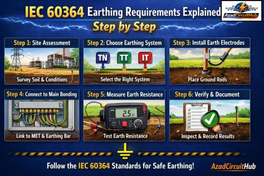
Table of Contents
Table of Contents
IEC 60364 is a global benchmark for electrical installations in buildings. It specifies how earthing should be designed, tested, and maintained. The main purpose is to protect human life, safeguard equipment, and ensure that installations operate safely under normal and fault conditions. Earthing ensures that dangerous voltages do not appear on exposed conductive parts of equipment, and that fault currents have a low-resistance path back to the source.
Understanding IEC 60364 Earthing Requirements is not only important for compliance but also for building trust in the safety and performance of electrical installations. Industrial facilities, residential buildings, commercial complexes, and even renewable energy systems like solar power plants depend on these guidelines to avoid electrical hazards such as shocks, fires, and equipment failures.
Importance of IEC 60364 Earthing Requirements
The IEC 60364 standard has become a cornerstone in modern electrical engineering. Its earthing requirements ensure that any fault, such as insulation failure or accidental contact with live parts, is managed safely. Earthing provides a defined path for current to return to the source, preventing high voltages from appearing on metallic enclosures.
One of the most important functions is the protection of people from electric shock. If exposed conductive parts become energized due to a fault, the earthing system ensures quick disconnection by tripping protective devices like fuses or circuit breakers. Without compliance with IEC 60364 Earthing Requirements, even minor faults could escalate into life-threatening situations.
In addition to personal safety, earthing also protects equipment. Transient overvoltages, lightning strikes, or switching surges can damage sensitive electronics. A properly designed earthing network dissipates these excess energies into the ground, minimizing operational risks.
For proper conductor selection and installation, check our detailed guide to Earthing Cable Size Standard and find the recommended sizes for different earthing applications.
Scope of IEC 60364 Earthing Requirements
The scope of IEC 60364 is broad. It covers low-voltage electrical installations in residential, commercial, and industrial applications. The standard outlines:
- Methods for connecting exposed conductive parts to earth.
- Types of earthing arrangements suitable for different supply systems.
- Guidelines for fault protection and protective conductor sizing.
- Coordination with protective devices to ensure disconnection times.
- Consideration of environmental factors such as soil resistivity and corrosion.
Unlike local codes, which may focus only on specific regions, IEC 60364 is globally harmonized. Many countries either adopt it directly or use it as the foundation for their national standards.
Types of Earthing Requirements in IEC 60364
IEC 60364 classifies earthing systems based on the relationship between the power supply and the exposed conductive parts. The three main types are TN, TT, and IT.
TN System
In TN systems, the neutral of the supply is directly earthed, and exposed conductive parts of the installation are connected to this point. The TN system is further divided into:
- TN-S: Separate neutral (N) and protective earth (PE) conductors throughout the system.
- TN-C: Neutral and protective earth are combined in a single conductor (PEN).
- TN-C-S: A combination where neutral and earth are combined in part of the system, then separated downstream.
TN systems are widely used in urban power distribution because they offer low impedance fault paths and reliable protection.
TT System
In TT systems, the supply has its own earth connection, and the consumer installation uses a separate earth electrode. There is no direct metallic connection between supply earth and consumer earth. This arrangement is common in rural areas or isolated installations. The main challenge is achieving a low earth resistance to ensure proper fault clearance.
IT System
In IT systems, the supply has no direct connection to earth or is connected through a high impedance. Exposed conductive parts are earthed individually or collectively. IT systems are preferred in locations where continuity of supply is critical, such as hospitals or industrial plants. Since the first fault does not cause immediate disconnection, monitoring devices are essential to detect insulation failures.
| Earthing Arrangement | Supply Neutral Connection | Consumer Earth | Typical Applications |
|---|---|---|---|
| TN-S | Neutral directly earthed, separate PE | Connected to supply earth | Urban networks, commercial buildings |
| TN-C | Neutral and PE combined (PEN) | Connected to supply earth | Old networks, cost-saving designs |
| TN-C-S | PEN upstream, PE and N separated downstream | Connected to supply earth | Modern utility supplies |
| TT | Neutral earthed, consumer has own electrode | Separate earth electrode | Rural, standalone houses |
| IT | Neutral unearthed or high impedance earthed | Equipment individually earthed | Hospitals, industries |
Know more about European Earthing System TN-S TN-C-S TT
Minimum Wire Size for Metallic Pipe Earthing Connection
During domestic building earthing work, a metallic pipe that forms part of an extraneous-conductive-part should be connected to the protective equipotential bonding system, with continuity verified before energising. Under IEC 60364 earthing Requirements, the minimum conductor size depends on whether the conductor is a protective conductor (PE) or a main protective bonding conductor.
| Connection / Conductor | IEC 60364-5-54 sizing principle | Common minimum copper provision* |
|---|---|---|
| Main protective bonding conductor | ≥ ½ of largest required PE | 6 mm² Cu often used as a practical minimum |
| PE conductor | Sized from circuit protective-device requirements | 2.5 mm² Cu if mechanically protected |
| PE conductor | Same as above | 4 mm² Cu if not mechanically protected |
| Main earthing conductor | Sized according to IEC 60364-5-54 | Minimum depends on installation and fault conditions |
*Local wiring regulations may impose different minimums.
For example, if the largest protective conductor requires 10 mm² copper, a calculated main bonding conductor would generally be at least 5 mm², subject to the applicable minimum and local rules. The resident engineer should verify conductor sizing, termination security, continuity, corrosion protection, and accessibility before energisation.
Key Checks Before Energising
| Inspection | Requirement |
|---|---|
| Metallic pipe connection | Bond securely to the protective equipotential bonding system |
| Continuity | Verify with an appropriate low-resistance continuity test |
| Conductor size | Confirm against IEC 60364-5-54 and local regulations |
| Connections | Tight, corrosion-resistant and mechanically protected |
| Identification | Protective/bonding conductors identified according to local wiring rules |
For practical domestic installations, never select the conductor solely from a generic wire-size chart; the fault-current path, protective-device characteristics, mechanical protection and national requirements must also be considered.
Not sure which protective conductor size to use? See our Earthing Cable Size Standard guide for practical sizing information based on common electrical installation requirements.
Protective Measures in IEC 60364 Earthing Requirements
IEC 60364 does not consider earthing in isolation. Protection depends on a combination of earthing and protective devices. The standard emphasizes coordination between earthing, overcurrent devices, and residual current devices (RCDs).
- Fault Protection: Ensures disconnection of supply in case of a fault. For TN systems, low fault loop impedance ensures quick tripping. For TT systems, RCDs are essential because earth resistance may be too high.
- Basic Protection: Prevents contact with live parts through insulation, barriers, and enclosures.
- Automatic Disconnection of Supply (ADS): Key requirement of IEC 60364. It mandates that in the event of a fault, supply must be automatically disconnected within a specified time depending on system voltage.
For example, in TN systems up to 230 V, disconnection must occur within 0.4 seconds.
| System Type | Maximum Disconnection Time at 230 V |
|---|---|
| TN | 0.4 s |
| TT | 0.2 – 1 s (depending on device rating) |
| IT | First fault monitored, disconnection on second fault |
Factors Affecting Earthing Design
While IEC 60364 Earthing Requirements provide general rules, practical implementation depends on several factors:
Soil Resistivity: High resistivity soils like rocky or sandy terrain make it difficult to achieve low earth resistance. Engineers often use multiple electrodes or chemical earthing to reduce resistance.
Electrode Material and Size: Copper, galvanized steel, and stainless steel are common choices. IEC 60364 specifies minimum cross-sectional areas for protective conductors and earth electrodes.
Fault Current Levels: The design must handle the magnitude and duration of expected fault currents.
Environmental Conditions: Corrosion, moisture, and temperature changes affect earthing system reliability.
Coordination with Protection Devices: The earthing system must ensure that fault currents activate breakers or RCDs within required times.
Testing and Verification under IEC 60364
IEC 60364 requires verification of earthing systems before commissioning. Testing ensures compliance and long-term safety. The main tests include:
- Earth Resistance Measurement: Using fall-of-potential or clamp methods to confirm electrode resistance.
- Continuity Test: Verifying that protective conductors are continuous and properly connected.
- Fault Loop Impedance Test: Ensuring that the impedance of the fault loop is low enough to trip protective devices.
- RCD Testing: Checking sensitivity and tripping times of residual current devices.
Routine inspections are also recommended to identify degradation, corrosion, or loose connections.
Before finalizing your earthing design, review our Earthing Cable Size Standard guide to understand cable sizing, conductor requirements, and installation considerations.
Advantages of Complying with IEC 60364 Earthing Requirements
Compliance with IEC 60364 provides multiple benefits:
- Enhanced safety for people and property.
- Compliance with international standards simplifies project approvals and reduces liability.
- Improved system reliability by minimizing equipment failures due to surges or faults.
- Easier integration of renewable energy systems, which require robust earthing for inverters and protective devices.
- Global recognition makes designs more future-proof as industries move toward harmonized electrical safety standards.
Earthing Requirements for Containers
For safe container installations, earthing requirements for containers should be designed around IEC 60364 protective bonding principles. The container’s metallic frame, doors, panels, and other exposed-conductive-parts should be bonded to the protective conductor (PE) so a fault can produce sufficient current to operate the protective device. Under IEC 60364 earthing principles, the PE conductor must be sized according to the applicable installation method and fault conditions.
| Requirement | Typical requirement / standard basis |
|---|---|
| Container metal frame | Bond to PE conductor |
| Doors and removable panels | Bond where required for electrical continuity |
| PE conductor | Sized according to IEC 60364-5-54 |
| Earth electrode | Required where the installation earthing arrangement calls for one |
| Earth resistance | No universal IEC 60364 value; determined by the earthing system and protective-device requirements |
| Protective disconnection | Must satisfy IEC 60364-4-41 |
For a TN system, verify that the earth fault loop impedance permits automatic disconnection within the applicable IEC 60364 limits. For TT systems, electrode resistance and RCD characteristics must satisfy the applicable disconnection condition. Always verify the complete installation against the local electrical code and supply arrangement.
Need an earth electrode or PE conductor sized correctly? Use the applicable IEC 60364 requirements rather than relying on a single “container earth resistance” value.
Earth Fault Impedance Calculation in IEC 60364 Earthing Design
Earth fault impedance is important when applying IEC 60364 Earthing Requirements, because the fault loop must have sufficiently low impedance to allow the protective device to disconnect the circuit within the required time. A basic calculation uses the prospective fault current and the total fault-loop impedance.
| Parameter | Description |
|---|---|
| Earth fault loop impedance | |
| Voltage to earth | |
| Current required for automatic disconnection |
The simplified relationship is:
Zs ≤ U₀ / Ia
When designing or verifying an installation, conductor resistance, protective conductor paths, supply impedance, and connections should all be considered. For practical examples, testing methods, formulas, and worked calculations, see this detailed guide to Earth Fault Impedance Calculation.
This check helps confirm that the earthing and protective-disconnection arrangement works as intended rather than relying only on the earth electrode resistance.
Earthing in Outdoor Handrailing
For earthing in outdoor handrailing, IEC 60364 requires exposed-conductive metalwork that can become live under an insulation fault to be connected to the protective earthing system where applicable. Metal handrails should therefore be bonded when they form part of, or are electrically connected to, exposed-conductive-parts of the installation. The exact conductor size depends on the installation’s protective-conductor arrangement and fault-protection design.
| Item | Typical requirement / value | IEC 60364 consideration |
|---|---|---|
| Protective conductor | Copper PE sized by installation design | IEC 60364-5-54 |
| Minimum copper PE | 2.5 mm² Cu with mechanical protection; 4 mm² Cu without it | Common minimum provisions under IEC 60364-5-54 |
| Main bonding conductor | Generally ≥ 6 mm² Cu where applicable | Verify based on supply/protective-conductor arrangement |
| Continuity | Low-resistance, permanent connection | Connections must remain reliable |
| Outdoor handrail | Bond if it is an exposed-conductive-part or requires protective equipotential bonding | Assess electrically, not simply by location |
Important: IEC 60364 does not specify one universal “handrail earthing resistance” or a single conductor size for every outdoor handrail. The design should verify automatic disconnection, fault current, conductor withstand and protective-device operation. For a complete iec 60364 earthing design, corrosion-resistant terminals and protected bonding connections are particularly important outdoors.
Effective Double Earthing vs Single Earthing
When comparing effective double earthing vs single earthing, the key difference is redundancy. A single earth electrode can provide an adequate fault-current path when correctly designed, tested, and coordinated with the protective device. Double earthing uses two independent electrodes or parallel earthing paths to improve reliability if one connection deteriorates.
For IEC 60364 earthing installations, there is no universal rule that every system must have two earth electrodes. The electrode arrangement must achieve effective protective measures and automatic disconnection of supply within the applicable requirements.
| Factor | Single Earthing | Double Earthing |
|---|---|---|
| Earth electrodes | 1 | 2 or more |
| Main benefit | Simpler installation | Greater redundancy |
| Fault protection | Must meet ADS requirements | Must meet ADS requirements |
| Electrode resistance | No universal IEC value | No universal IEC value |
| Testing | Required | Each electrode/path should be verified |
| Typical use | Domestic/small installations | Critical or higher-reliability installations |
For example, adding a second electrode does not automatically make a system safer if bonding, conductor sizing, joints, or protective-device settings are inadequate. Under IEC 60364, verify the earth fault loop impedance, protective conductor continuity, and automatic disconnection time rather than selecting double earthing solely to achieve a particular resistance value.
For installations where reliability is critical, professionally installed and tested parallel earthing paths can provide useful redundancy. Affiliate buyers should also select a properly rated earth resistance tester rather than relying on inexpensive resistance meters.
Cable Rack Earthing Inspection Requirements
For compliant cable rack earthing, inspect the rack bonding, protective conductor connections, mechanical integrity, continuity, and corrosion protection before energizing. Under IEC 60364 earthing principles, exposed conductive parts must be connected to the protective earthing system so that fault current can operate the protective device within the required disconnection time.
IEC 60364-5-54 covers protective conductors and earthing arrangements, while SANS 10142-1 provides South African installation requirements based on IEC principles.
| Inspection item | Requirement / value | Standard reference |
|---|---|---|
| Rack-to-rack bonding | Reliable electrical bond at every required section/joint | IEC 60364-5-54 |
| Protective conductor | Sized according to installation fault/protective-conductor requirements | IEC 60364-5-54, SANS 10142-1 |
| Continuity | Low-resistance, continuous PE path; verify by testing | IEC 60364-6 |
| Connections | Tight, corrosion-resistant and mechanically secure | IEC 60364-5-54 |
| Earth connection | Connect rack system to the main earthing/protective bonding system | IEC 60364-5-54 |
| Corrosion | No excessive rust, paint, or contamination at bonding points | IEC 60364-5-54 |
| Verification | Continuity, protective-conductor and relevant fault-loop tests | IEC 60364-6 |
Important: IEC 60364 does not prescribe one universal “rack earth resistance” value. The required result depends on the earthing system and automatic disconnection requirements. SANS 10142-1 should be applied for South African installations, together with the applicable equipment and project specifications.
Grounding and Earthing Mesh Systems: Minimum Earth Continuity and Resistance Requirements
For a grounding or earthing mesh, testing should verify a continuous low-impedance path from the main earthing terminal (MET) to the final exposed-conductive-part or earth point of the subsystem. Under IEC 60364 earthing, protective conductors must provide a reliable fault-current path and maintain continuity throughout the installation.
| Test parameter | Minimum requirement / guidance | IEC 60364 reference |
|---|---|---|
| Protective conductor continuity | Continuous, with no open circuit | IEC 60364-6 |
| Protective conductor resistance | As low as practicable; verify against calculated/design value | IEC 60364-6 |
| Earth-fault loop impedance | Must permit automatic disconnection | IEC 60364-4-41 |
| TT system earth resistance | Must satisfy RA × Ia ≤ 50 V | IEC 60364-4-41 |
| TN system | Loop impedance must satisfy automatic-disconnection conditions | IEC 60364-4-41 |
| Continuity test current | Typically ≥200 mA for protective-conductor continuity testing | IEC 60364-6 |
A single universal “maximum earth resistance” value does not apply to every installation. The required value depends on the earthing arrangement, protective-device characteristics, fault level and design. For commissioning, measure continuity from the MET to each final earth point and record the measured resistance against the calculated/design limit.
For larger mesh systems, use an appropriate earth resistance/ground impedance tester and document all test points. This provides stronger verification than relying only on a single electrode resistance measurement.
IEC 60364 HVAC Duct Grounding Requirements
Proper iec 60364 hvac duct grounding connects exposed conductive HVAC ductwork to the protective equipotential bonding system so a fault does not leave dangerous touch voltage on metal surfaces.
IEC 60364-4-41 requires automatic disconnection of supply under applicable fault conditions, while IEC 60364-5-54 covers protective conductors and equipotential bonding. For installations covered by iec 60364 earthing, the bonding conductor must be selected according to the installation design and fault-current requirements rather than using one fixed duct-grounding size.
| HVAC grounding item | IEC 60364 approach |
|---|---|
| Metal ductwork | Bond where required as an exposed/extraneous conductive part |
| Bonding conductor | Size according to IEC 60364-5-54 |
| Protective conductor | Sized for fault protection and disconnection |
| Connection | Permanent, electrically reliable, corrosion-resistant |
| Target earth resistance | No universal HVAC-duct value specified by IEC 60364 |
Typical Bonding Guidance
| Installation | Practical requirement |
|---|---|
| Duct sections with reliable electrical continuity | Verify continuity and bond as required by the protective-bonding design |
| Flanged/flexible connections | Provide bonding where continuity can be interrupted |
| Painted or insulated joints | Ensure a suitable bonding connection bypasses the insulating surface |
| Large metal HVAC systems | Include in the building equipotential bonding assessment |
For an affiliate-friendly installation guide, recommend a listed grounding/bonding clamp, approved bonding jumper, and suitable copper protective conductor selected for the actual fault conditions and local code requirements. Do not substitute a generic “duct ground wire size” for the engineering calculation.
Conclusion
The IEC 60364 Earthing Requirements are not just technical rules; they are life-saving measures. By defining how electrical installations should be earthed, the standard reduces risks of shock, fire, and equipment failure. Engineers, contractors, and facility managers must understand and apply these requirements carefully.
Whether working with TN, TT, or IT systems, the principle remains the same: provide a safe, low-resistance path for fault currents and ensure protective devices operate correctly. Testing, verification, and maintenance are equally important to ensure long-term compliance.
ICT system earthing how many ohms
An ICT system earthing resistance is commonly designed to be 10 ohms or less.
For sensitive ICT/data-center systems, 1–5 ohms or lower may be specified by the project or equipment manufacturer.
Is it OK to loop the main earthing of machines from a common bar?
Yes, machines can be connected to a common earth bar, but each machine should preferably have its own dedicated protective earth conductor to the bar. Avoid relying on one machine’s earth connection to provide the earth path for another.
How good do we need the contact between joints for earthing?
Earthing joints should provide a clean, tight, and low-resistance electrical connection that remains reliable under fault current. Connections should be mechanically secure, corrosion-resistant, and properly bonded using approved clamps, lugs, or suitable joining methods.
Which type of earthing should be done in a PD testing lab?
A PD (Partial Discharge) testing lab should use a low-impedance, dedicated protective earthing system, preferably an integrated earth grid or ground plane.
It should provide effective bonding of the test equipment, enclosure, test object, and shields to minimize noise and ensure personnel safety during high-voltage testing.
Why are lugs required for an earth pit?
Lugs provide a secure, low-resistance connection between the earthing conductor and the earth electrode or earth pit connection point. They improve mechanical strength, electrical continuity, and help prevent loose or corroded connections.
What is the ring network code for earth fault protection?
Ring networks commonly use IEC 60255 for protection relay requirements, while the specific earth-fault protection scheme depends on the network design and utility standard. For ring-main systems, directional or non-directional earth-fault relays may be used as required.
Can we do the earthing inside the factory building?
Yes, earthing can be installed inside a factory building, provided the earthing system is properly designed and complies with applicable electrical standards. The earth electrode or earth grid should be located where it remains accessible, protected, and suitable for safe fault-current dissipation.
What is the difference between electrical earthing and instrument earthing?
Electrical earthing protects people and equipment from fault currents, while instrument earthing provides a stable, low-noise reference for sensitive control and measurement devices. Instrument earthing is typically kept separate from power earthing to minimize electrical noise and interference.
Does an earthing pin require an oxygen concentrator plug top?
Yes, if the oxygen concentrator has a Class I metal-bodied design, its plug should have an earth pin. This provides a protective earth connection to reduce electric-shock risk in case of an insulation fault.
Why is door earthing required in an electrical panel?
Door earthing is required to maintain electrical continuity between the panel door and the grounded enclosure.
It provides a safe path for fault current if a live conductor contacts the metal door, helping prevent electric shock.
A flexible bonding wire or earth braid is commonly used to connect the door to the main panel body.
How many earthing points are required on a duct?
A metallic electrical duct should have earthing/bonding connections to maintain electrical continuity and provide a safe fault-current path. The exact number depends on the duct length, joints, installation type, and applicable electrical standard.
What is the bonding resistance as per IEC 60364?
IEC 60364 does not specify one universal maximum bonding resistance value; protective bonding conductors should provide a sufficiently low impedance for protective devices to operate effectively. The required value depends on the installation design, fault protection method, and applicable national requirements.
Is it allowed to use salt for earthing according to IEEE?
IEEE standards do not generally recommend salt as a routine earthing-enhancement material because it can accelerate corrosion and contaminate soil. Modern earthing systems should use suitable electrodes and approved backfill/ground-enhancement materials where required.
Related Guides & Tools
Follow Us on Social:
Subscribe our Newsletter on Electrical Insights for latest updates from Electrical Engineering Hub
#IEC60364, #EarthingRequirements, #ElectricalEarthing, #ElectricalSafety, #GroundingSystem, #ProtectiveConductor, #EquipotentialBonding, #IECStandards, #ElectricalEngineering, #EarthingSystem