
Earth Fault Impedance Calculation: Formula, Values, Testing and Examples
Earth fault impedance is an important part of electrical installation design because it determines whether enough fault current will flow to operate the protective device quickly. A correct earth fault impedance calculation helps confirm that the protective conductor, earthing system, supply conductors, and overcurrent device can provide an effective fault-clearing path.
For a TN system, the earth fault loop impedance is commonly checked against the maximum value permitted for the protective device. If the impedance is too high, the fault current may be too low to disconnect the circuit within the required time.
| Parameter | Typical Symbol | Unit | Purpose |
|---|---|---|---|
| Earth fault loop impedance | Zs | Ω | Total impedance of the fault path |
| Prospective fault current | Ipf | A | Current expected during a fault |
| Supply voltage | U0 | V | Voltage to earth |
| Protective device | MCB, fuse, RCBO | — | Disconnects the faulty circuit |
| Protective conductor | PE/CPC | mm² | Provides the fault return path |
| Earth electrode resistance | RA | Ω | Relevant to TT earthing systems |
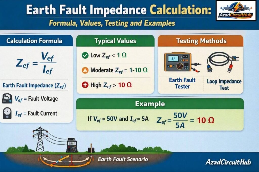
Table of Contents
Table of Contents
What Is Earth Fault Impedance?
Earth fault impedance is the total impedance encountered by fault current when a line conductor contacts exposed conductive parts connected to earth. It includes the source impedance, line conductor resistance, protective conductor resistance, and other impedance in the fault path.
In a typical TN arrangement, the complete earth fault loop runs from the transformer through the line conductor to the fault point, returns through the protective conductor and supply earthing path, and finally reaches the transformer winding.
A lower loop impedance normally produces a higher fault current. This allows an MCB or fuse to disconnect the circuit rapidly when a phase-to-earth fault occurs.
Earth Fault Impedance Calculation Formula
The basic relationship between fault voltage, fault current, and impedance is:
Zs = U0 / Ia
Where:
- Zs = earth fault loop impedance in ohms
- U0 = nominal voltage to earth in volts
- Ia = current required to operate the protective device within the specified time
For a simple fault-current estimate, the relationship can also be written as:
Ipf = U0 / Zs
For example, if the voltage to earth is 230 V and the measured loop impedance is 0.80 Ω:
Ipf = 230 / 0.80 = 287.5 A
The calculated prospective earth fault current is therefore approximately 288 A.
| Voltage to Earth | Loop Impedance | Approx. Fault Current |
|---|---|---|
| 230 V | 0.20 Ω | 1,150 A |
| 230 V | 0.40 Ω | 575 A |
| 230 V | 0.60 Ω | 383 A |
| 230 V | 0.80 Ω | 288 A |
| 230 V | 1.00 Ω | 230 A |
| 230 V | 1.50 Ω | 153 A |
| 230 V | 2.00 Ω | 115 A |
These values are simplified calculations. Actual fault current depends on the complete impedance of the supply and fault path.
For accurate conductor selection and safe fault-current paths, check our guide to Earthing Cable Size Standard and find the recommended sizes for different electrical installations.
How to Calculate Earth Fault Loop Impedance
A practical earth fault impedance calculation can be completed using the installation voltage and the expected fault current.
Consider a 230 V single-phase circuit protected by a 32 A Type B MCB. Assume the required instantaneous operating current is approximately 160 A for the design check.
Using:
Zs = U0 / Ia
Zs = 230 / 160
Zs = 1.44 Ω
The calculated maximum loop impedance is approximately 1.44 Ω under these simplified assumptions.
However, the actual maximum permitted Zs should be taken from the applicable wiring regulations, protective-device characteristics, manufacturer data, and any required correction factors. Do not use a generic value as a substitute for the applicable standard.
Example Using Measured Values
Suppose an electrician measures the following:
| Measurement | Value |
|---|---|
| Supply voltage | 230 V |
| Measured Zs | 0.72 Ω |
| Circuit protective device | 32 A MCB |
| Estimated fault current | 319 A |
The prospective fault current is:
Ipf = 230 / 0.72 = 319.4 A
A fault current of about 319 A indicates a relatively low impedance fault path. The electrician must then verify that the protective device can disconnect within the required time at that fault current.
Why Earth Fault Impedance Matters
A fault current must have a suitable return path. If the path has excessive resistance or impedance, the fault current can become too small to operate an MCB or fuse quickly.
High impedance can result from:
- Long cable runs
- Undersized protective conductors
- Loose terminals
- Corroded connections
- Poor earthing connections
- High supply impedance
- Damaged conductors
- Incorrect bonding
- Poor connections at distribution boards
This is why earth fault impedance calculation should be considered alongside conductor sizing, voltage drop, short-circuit protection, and protective conductor selection.
For a broader review of installation earthing, bonding, and protective conductor requirements, see our guide to iec 60364 earthing Requirements.
Earth Fault Impedance in TN and TT Systems
The method of checking fault protection differs between earthing arrangements.
In a TN system, the fault current generally returns to the source through a metallic protective path. This can produce a sufficiently high fault current for an MCB or fuse to operate.
In a TT system, the installation relies heavily on earth electrodes. The earth electrode resistance can be much higher than the impedance of a metallic return path. Residual current protection is therefore commonly important for automatic disconnection.
| Earthing System | Main Fault Return Path | Important Parameter |
|---|---|---|
| TN-S | Protective conductor and source earth | Zs |
| TN-C-S | PEN/source arrangement and protective conductor | Zs |
| TT | Installation earth electrode and supply electrode | RA |
| IT | High-impedance or isolated source arrangement | Insulation monitoring |
The applicable installation standard should always be checked before deciding which disconnection method applies.
Earth Fault Impedance vs Earth Electrode Resistance
These terms are related but they are not interchangeable.
Earth electrode resistance describes the resistance between an earth electrode and the surrounding soil. Earth fault loop impedance describes the total impedance of the complete fault circuit.
| Feature | Earth Electrode Resistance | Earth Fault Loop Impedance |
|---|---|---|
| Symbol | RA | Zs |
| Main application | TT and electrode systems | Fault protection assessment |
| Measurement | Earth resistance tester | Loop impedance tester |
| Includes complete fault loop? | No | Yes |
| Unit | Ω | Ω |
A low electrode resistance does not automatically mean that the complete earth fault loop impedance is low.
How to Measure Earth Fault Loop Impedance
An installation tester can be used to measure loop impedance at the relevant point in an electrical installation. The test instrument applies a controlled test condition and determines the impedance of the circuit.
A typical procedure includes:
- Confirm the circuit identification and protective device.
- Verify that the test instrument is suitable for the installation.
- Check the condition of the installation before testing.
- Perform the appropriate loop impedance test.
- Record the measured Zs value.
- Compare the result with the permitted value for the protective device.
- Investigate unusually high readings.
Some modern testers provide no-trip loop testing where appropriate, which can reduce unwanted RCD operation during testing. The manufacturer’s instructions must be followed.
For a complete installation design reference, review iec 60364 earthing Requirements to understand how protective conductors, bonding, and automatic disconnection fit together.
Factors That Increase Earth Fault Impedance
Several installation conditions can increase the measured value.
| Cause | Effect |
|---|---|
| Long circuit | Higher conductor impedance |
| Small CPC | Higher protective conductor resistance |
| Loose terminal | Increased contact resistance |
| Corrosion | Poor electrical connection |
| High supply impedance | Lower available fault current |
| Poor bonding | Increased fault-path impedance |
| Incorrect conductor size | Higher resistance and possible overheating |
Temperature also affects conductor resistance. Copper resistance increases as conductor temperature rises, so design calculations may need appropriate correction.
Earth Fault Impedance and Protective Device Selection
The protective device must be suitable for the expected fault conditions. An MCB does not simply need to carry the normal load current; it must also provide appropriate fault protection.
For example, selecting a breaker based only on the normal circuit load can overlook the available fault current and required disconnection time.
A proper design considers:
- Circuit operating current
- Cable ampacity
- Protective device rating
- Protective device characteristic
- Prospective fault current
- Loop impedance
- Disconnection time
- Cable thermal withstand
- Supply characteristics
For additional guidance on installation earthing and protective measures, see iec 60364 earthing Requirements.
Earth Fault Impedance Calculation for Cable Design
Cable resistance contributes to the total fault loop impedance. For a conductor, resistance can be estimated using:
R = ρL / A
Where:
- R = conductor resistance
- ρ = resistivity of the conductor material
- L = conductor length
- A = conductor cross-sectional area
Both the line conductor and protective conductor contribute to the fault path. For long circuits, their combined resistance can become significant.
For copper conductors, designers often use temperature-adjusted resistance rather than relying only on the resistance at 20°C.
Common Mistakes When Checking Fault Impedance
One common mistake is treating earth electrode resistance as the same measurement as loop impedance. They measure different parts of an electrical system.
Another mistake is using a maximum Zs value without confirming the protective device and applicable standard. Breaker type, rating, operating characteristic, voltage, and disconnection requirements all matter.
It is also important not to assume that a low measured impedance automatically proves the entire installation is safe. Protective conductor continuity, polarity, insulation resistance, RCD operation, bonding, and other required tests should also be completed.
Quick Earth Fault Impedance Reference
| Calculation | Formula |
|---|---|
| Fault current | Ipf = U0 / Zs |
| Loop impedance | Zs = U0 / Ia |
| Conductor resistance | R = ρL / A |
| Voltage drop | ΔV = I × R |
These formulas provide useful engineering estimates, but final compliance should be based on the applicable electrical installation standard and verified test results.
Frequently Asked Questions
What is earth fault impedance?
Earth fault impedance is the total impedance of the electrical path followed by current during an earth fault. It includes the relevant supply, line conductor, protective conductor, and return path impedances.
What is the formula for earth fault loop impedance?
The basic formula is Zs = U0 / Ia, where Zs is loop impedance, U0 is voltage to earth, and Ia is the current needed to operate the protective device within the required disconnection time.
What happens if earth fault loop impedance is too high?
High loop impedance limits fault current. If the current is insufficient to operate the protective device quickly, automatic disconnection may not occur within the required time.
Is earth resistance the same as earth fault loop impedance?
No. Earth resistance usually refers to the resistance of an earth electrode or grounding system, while loop impedance represents the impedance of the complete fault-current path.
How do you test earth fault loop impedance?
A suitable electrical installation tester is connected at the required test point and measures the impedance of the fault loop. The measured result is then compared with the applicable limit for the protective device and installation.
Final Takeaway
A reliable earth fault impedance calculation connects the theoretical design with practical fault protection. By calculating the expected fault current, checking conductor resistance, selecting the correct protective device, and verifying the installation with appropriate testing, electricians and engineers can confirm that automatic disconnection is likely to operate as intended.
The final assessment should always consider the applicable wiring regulations, protective-device characteristics, conductor sizes, earthing arrangement, and measured test results rather than relying on a single impedance value.
Get new guides in your feed. Follow Electrical Insights on LinkedIn for new electrical standards guides, calculators and design tips from Azad Circuit Hub.
#EarthFaultImpedance, #EarthFaultLoopImpedance, #ElectricalSafety, #FaultCurrent, #EarthingSystem, #ImpedanceCalculation, #ElectricalTesting, #ProtectiveDevices, #IEC60364, #ElectricalEngineering
