
Earth Fault Relay Setting Calculator | IEC 60255-151 & IEEE C37.112
Electrical protection systems must detect ground faults quickly while avoiding unnecessary trips. An Earth Fault Relay Setting Calculator helps engineers, technicians, and electricians determine suitable pickup current and time delay settings for reliable fault protection. Proper relay settings improve equipment safety, reduce downtime, and ensure selective coordination with upstream and downstream protective devices.
Whether you are commissioning a new electrical system or reviewing an existing protection scheme, understanding earth fault relay settings is essential for maintaining system reliability and complying with IEC 60255, IEEE C37.112, and utility protection practices.
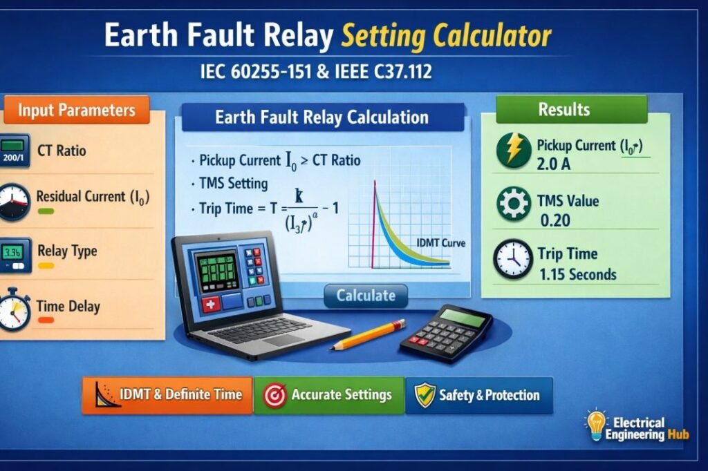
Table of Contents
Table of Contents
Earth Fault Relay Setting Calculator
Earth Fault Relay Setting Calculator
Determine earth fault (ground fault) relay pickup, operating time and grading margin for solidly earthed, resistance earthed and isolated systems, referenced against IEC 60255-151 and IEEE C37.112 characteristic families.
System & Relay Parameters
Calculated Settings
Time-Current Characteristic
Log-log plot of relay operating time against fault current expressed as a multiple of the primary pickup setting. Marker shows the operating point at the entered maximum earth fault current.
How to Use
- Select the system earthing arrangement. This changes the sensitivity guidance shown beneath the input fields.
- Enter the CT primary rating and secondary rating (1 A or 5 A), and select whether earth fault sensing uses a core balance CT or a residual connection of three line CTs.
- Enter the desired pickup setting as a percentage of the CT secondary rated current, along with the time multiplier setting and curve type from the relay’s setting range.
- Enter the maximum earth fault current expected at the relay location, and the minimum earth fault current expected at the remote end of the protected zone.
- Enter the operating time of the downstream protective device at the same maximum fault current, so the grading margin can be checked.
- Review the calculated pickup currents, operating time, sensitivity check and grading margin on the right, and the plotted time-current characteristic below.
- Adjust the pickup percentage, TMS or curve type until both checks show a pass status, then transfer the final values to the physical relay settings.
Reference Notes
Curve shapes correspond to the IEC 60255-151 standard inverse, very inverse, extremely inverse and long time inverse families, together with definite time operation, as commonly offered on numerical earth fault relays.
For high resistance earthed and isolated / compensated systems, fault current at the relay location can be very small, and dedicated sensitive earth fault (SEF) elements with millampere-range pickup and, where required, directional supervision are typically used instead of a standard phase-type earth fault element.
CT knee point voltage, saturation behaviour and burden should be checked separately to confirm the selected CT can reproduce the fault current accurately at the chosen pickup setting, particularly for core balance CTs at low primary fault levels.
Grading margins shown here follow general coordination practice; the specific margin required depends on relay and breaker operating times, CT performance, and the utility or plant protection philosophy in use.
What Is an Earth Fault Relay Setting Calculator?
An Earth Fault Relay Setting Calculator is an engineering tool that calculates the recommended pickup current and operating time of an earth fault relay based on system parameters.
Instead of relying on trial-and-error values, the calculator uses electrical design inputs such as:
- Current transformer (CT) ratio
- Expected earth fault current
- Relay curve type
- Time Multiplier Setting (TMS)
- System voltage
- Grounding method
The calculated settings help the relay detect genuine earth faults while avoiding nuisance tripping caused by transient conditions.
Why Correct Earth Fault Relay Settings Matter
Improper relay settings can either delay fault clearance or create unnecessary outages.
Correct settings provide several advantages:
| Benefit | Description |
|---|---|
| Equipment Protection | Prevents damage to transformers, motors, generators, and cables |
| Personnel Safety | Reduces shock and arc flash risks |
| Selective Coordination | Trips only the affected feeder |
| Reduced Downtime | Limits interruption to healthy circuits |
| Standards Compliance | Supports IEC and IEEE protection practices |
Accurate relay settings also extend equipment life by minimizing thermal and mechanical stress during faults.
Inputs Required for Relay Calculation
Before using the calculator, collect the required electrical data.
| Input Parameter | Purpose |
|---|---|
| CT Ratio | Converts primary current to relay current |
| Rated Current | Used as a reference for pickup settings |
| Earth Fault Current | Determines relay sensitivity |
| Relay Curve | Defines operating characteristics |
| Time Multiplier Setting | Adjusts operating time |
| Grounding Type | Influences available fault current |
Reliable calculations always depend on accurate system study data.
Working Principle of an Earth Fault Relay
The Working Principle of an Earth Fault Relay is based on detecting residual current caused by insulation failure or an unintended path to earth. Under normal conditions, the vector sum of phase currents is zero. During an earth fault, this balance changes, and the relay senses the residual current through a core balance CT (CBCT) or by summing the three phase CTs.
If the measured current exceeds the pickup setting for the specified time delay, the relay issues a trip signal to isolate the faulty circuit and prevent equipment damage.
| Condition | Relay Response |
|---|---|
| Normal operation | No residual current detected; relay remains inactive |
| Earth fault occurs | Residual current exceeds pickup setting; relay trips after the configured delay |
For a detailed explanation with diagrams and practical examples, read our complete guide on the working principle of an earth fault relay.
Types of Earth Fault Relays
Selecting the correct Types of Earth Fault Relays is just as important as calculating the right pickup current and time settings. Different relay technologies are designed for specific protection applications, ranging from simple feeder circuits to sensitive equipment and high-resistance grounded systems. The table below provides a quick comparison.
| Earth Fault Relay Type | Typical Application | Key Advantage |
|---|---|---|
| Instantaneous Earth Fault Relay | Feeders, radial systems | Trips without intentional delay |
| Definite Time Earth Fault Relay | Distribution networks | Fixed operating time |
| Inverse Time Earth Fault Relay | Industrial and utility systems | Faster operation for higher fault currents |
| Directional Earth Fault Relay | Parallel feeders, ring networks | Detects fault direction accurately |
| Sensitive Earth Fault Relay | Generators, transformers, cables | Detects very low leakage currents |
For a detailed comparison, applications, and selection guidance, read our complete guide on Types of Earth Fault Relays. It explains when each relay type should be used and how it complements accurate relay setting calculations.
How Earth Fault Relay Settings Are Calculated
The calculation process follows a logical sequence.
Step 1: Determine Available Earth Fault Current
Calculate or obtain the maximum earth fault current from the short-circuit study.
Example:
- Earth fault current = 1200 A
Step 2: Select CT Ratio
Assume the feeder CT ratio is:
- 400/5 A
CT Ratio:
Primary Current ÷ Secondary Current
400 ÷ 5 = 80
Step 3: Calculate Relay Secondary Current
Relay Secondary Current = Primary Fault Current ÷ CT Ratio
1200 ÷ 80 = 15 A
This is the current seen by the relay.
Step 4: Select Pickup Current
Pickup current is generally selected between 10% and 40% of CT secondary rating depending on system design.
Example:
Relay Pickup = 1 A
The relay starts operating when current exceeds this value.
Step 5: Earth Fault Relay Time Delay Setting
The Time Multiplier Setting adjusts the relay operating time according to the selected inverse characteristic curve.
Typical TMS values range between:
- 0.05
- 0.10
- 0.20
- 0.30
- 0.50
The final value depends on coordination with upstream and downstream protection devices.
For detailed formula and calculation follow our guide on Earth Fault Relay Time Delay Setting
Difference Between Earth Fault Relay and Overcurrent
Understanding the Difference Between Earth Fault Relay and Overcurrent protection helps when selecting and setting protective relays. Earth fault relays respond specifically to current flowing through an unintended path to ground, while overcurrent relays generally operate when phase current exceeds a defined pickup level.
| Feature | Earth Fault Relay | Overcurrent Relay |
|---|---|---|
| Primary protection | Ground faults | Phase overcurrent |
| Sensing | Residual/zero-sequence current | Phase current |
| Typical fault | Phase-to-earth | Phase-to-phase or overload |
| Setting basis | Earth fault pickup | Load and fault current |
For practical relay coordination, pickup values and time delays should be calculated according to the applicable protection standard.
See the detailed guide on earth fault relay versus overcurrent protection to understand their operating principles, applications, and setting considerations.
Example Earth Fault Relay Calculation
The following example demonstrates the calculation process.
| Parameter | Value |
|---|---|
| System Voltage | 11 kV |
| CT Ratio | 400/5 |
| Earth Fault Current | 1200 A |
| Pickup Current | 1 A |
| Relay Curve | IEC Standard Inverse |
| TMS | 0.15 |
Calculation:
Relay Current = 1200 ÷ 80 = 15 A
Multiple of Pickup (M):
15 ÷ 1 = 15
Using the IEC Standard Inverse equation with TMS 0.15, the relay operating time can be calculated automatically by the calculator.
This eliminates manual calculations and reduces commissioning time. For detailed calculations follow our guide on How to Set Earth Fault Relay Settings Correctly? for accurate settings and step by step guide.
Earth Fault Relay Trip Characteristics
Understanding Earth Fault Relay Trip Characteristics helps engineers select suitable pickup and time-delay settings for dependable fault clearance. The relay response generally depends on fault current magnitude, pickup current, and the selected time-current curve.
| Characteristic | Typical Function |
|---|---|
| Pickup current | Minimum earth-fault current required to operate |
| Time delay | Controls how quickly the relay trips |
| Inverse curve | Higher fault current produces faster tripping |
| Definite-time | Trips after a fixed delay once pickup is exceeded |
For practical coordination, compare relay operating times with upstream and downstream protection. Correctly coordinated characteristics minimize unnecessary outages while maintaining fast fault clearance.
See the detailed guide on Earth Fault Relay Trip Characteristics for curve selection, operating-time calculations, and coordination considerations under IEC and IEEE practices.
Common Relay Curve Types
Modern numerical relays support several inverse-time characteristics.
| Relay Curve | Typical Application |
|---|---|
| Standard Inverse | General feeder protection |
| Very Inverse | Long distribution feeders |
| Extremely Inverse | Transformer and cable protection |
| Long-Time Inverse | Backup protection |
| Definite Time | Fixed operating delay applications |
Selecting the appropriate curve improves protection coordination across the system.
For a deeper understanding of ground-fault detection methods, see our guide to Residual vs Zero Sequence Ground Fault Protection and compare how each method responds to earth faults.
Earth Fault Relay Sensitivity Setting
An accurate Earth Fault Relay Sensitivity Setting is essential for detecting low-level ground faults without causing unnecessary trips. The pickup value should be selected according to the system earthing method, CT ratio, minimum expected fault current, and relay coordination requirements.
| Setting Parameter | Typical Consideration |
|---|---|
| Pickup current | Above normal residual current |
| Time delay | Based on coordination |
| CT ratio | Matches protection and fault levels |
| Sensitivity | Detects minimum earth-fault current |
For practical pickup calculations, coordination checks, and IEC/IEEE-based examples, see our detailed guide on Earth Fault Relay Sensitivity Setting. It explains how to select sensitivity and time delay while maintaining reliable protection.
Earth Fault Relay Testing Procedure
An Earth Fault Relay Testing Procedure verifies that the relay detects ground-fault current correctly and operates within its configured pickup and time-delay settings. Testing should be performed after commissioning, maintenance, or changes to protection settings.
| Test Step | What to Check |
|---|---|
| Visual inspection | Relay wiring, terminals, CT connections |
| Secondary injection | Apply simulated earth-fault current |
| Pickup test | Confirm relay operates at the set current |
| Time test | Verify operating time against the setting |
| Trip test | Confirm breaker trip command |
| Record results | Document measured values and deviations |
Before testing, isolate the equipment according to the applicable safety procedure. The calculated pickup value can be obtained using an Earth Fault Relay Setting Calculator, while the testing process confirms that the installed protection actually performs as expected.
For detailed test methods, injection values, and acceptance checks, follow the complete Earth Fault Relay Testing Procedure guide.
Recommended Pickup Settings
The pickup setting depends on the grounding method and application.
| Application | Typical Pickup Setting |
|---|---|
| Motor Feeders | 10–20% of CT rating |
| Distribution Feeders | 20–30% |
| Transformers | 20–40% |
| Generators | Based on manufacturer recommendations |
| Industrial Plants | According to protection coordination study |
Actual settings should always be verified through coordination analysis.
Want to understand the difference between these protection concepts? Explore our detailed guide on Ground Fault Protection vs Earth Leakage Protection for practical insights.
Factors Affecting Relay Settings
Several system conditions influence the final relay configuration.
Current Transformer Accuracy
An inaccurate CT can cause incorrect relay operation.
Grounding System
Solidly grounded systems produce higher earth fault currents than resistance-grounded systems.
Cable Length
Long feeders may reduce available fault current because of increased impedance.
Relay Coordination
Each relay should operate only after downstream devices fail to clear the fault.
System Expansion
Future load additions may require relay setting revisions.
Common Mistakes to Avoid
Engineers should avoid these common configuration errors.
| Mistake | Possible Result |
|---|---|
| Incorrect CT ratio | Wrong pickup current |
| Excessive pickup setting | Fault not detected |
| Very low pickup setting | Nuisance tripping |
| Poor coordination | Multiple breaker trips |
| Ignoring fault study | Unsafe protection system |
Regular testing and relay maintenance help prevent these issues.
IEC and IEEE Standards for Earth Fault Protection
Protection engineers commonly refer to internationally recognized standards during relay selection and setting.
| Standard | Purpose |
|---|---|
| IEC 60255 | Measuring relays and protection equipment |
| IEC 60909 | Short-circuit current calculation |
| IEEE C37.112 | Inverse-time overcurrent relay equations |
| IEEE C37 Series | Power system protection practices |
These standards provide guidance for relay performance, testing, and coordination.
Practical Applications
An Earth Fault Relay Setting Calculator is widely used across electrical industries.
Typical applications include:
- Utility substations
- Industrial manufacturing plants
- Commercial buildings
- Renewable energy systems
- Data centers
- Oil and gas facilities
- Water treatment plants
- Mining operations
Each installation requires settings based on its own fault level and protection study.
Best Practices for Relay Setting
Follow these recommendations for reliable protection.
- Verify short-circuit study results before calculation.
- Confirm the installed CT ratio.
- Choose the correct inverse-time characteristic.
- Coordinate with upstream and downstream relays.
- Test relay operation during commissioning.
- Review settings after system modifications.
- Maintain proper documentation for future maintenance.
These practices improve protection reliability and simplify troubleshooting.
Related Guides & Tools
- What Is Earth Fault Relay Protection Zone?
- Low Set and High Set Earth Fault Relays
- Overcurrent Relay Setting Calculator
Conclusion
An Earth Fault Relay Setting Calculator simplifies one of the most important tasks in electrical protection engineering. By calculating suitable pickup current and operating time, it helps achieve dependable fault detection, selective coordination, and improved equipment protection. Whether designing a new installation or upgrading an existing power system, using calculated relay settings instead of estimated values results in safer and more reliable operation.
For complete protection coordination, use the calculator together with your hub guide on relay setting calculations to compare earth fault, overcurrent, and overload protection settings within the same electrical system.
Get new guides in your feed. Follow Electrical Insights on LinkedIn for new electrical standards guides, calculators and design tips from Azad Circuit Hub.
#EarthFaultRelaySettingCalculator, #EarthFaultRelay, #ProtectionRelay, #RelaySettings, #PowerSystemProtection, #IEC60255151, #IEEEC37112, #ElectricalEngineering, #FaultProtection, #PowerEngineering
