Earth Fault Relay Time Delay Setting
| Parameter | Typical Consideration |
|---|---|
| Protection device | Earth fault relay |
| Main purpose | Detect ground or earth faults |
| Time delay | Allows downstream protection to operate first |
| Setting basis | Fault current, system configuration, CT ratio, and coordination |
| Common setting range | Depends on relay and protection scheme |
| Coordination method | Time-current grading |
| Main objective | Selective fault isolation |
| Important standards | IEC 60255, IEC 60947, IEEE protection practices |
Earth fault protection is essential for limiting damage caused by current flowing from a phase conductor to earth. However, detecting the fault is only one part of a reliable protection scheme. The relay must also operate at the correct time so that the nearest protective device clears the fault before an upstream breaker trips.
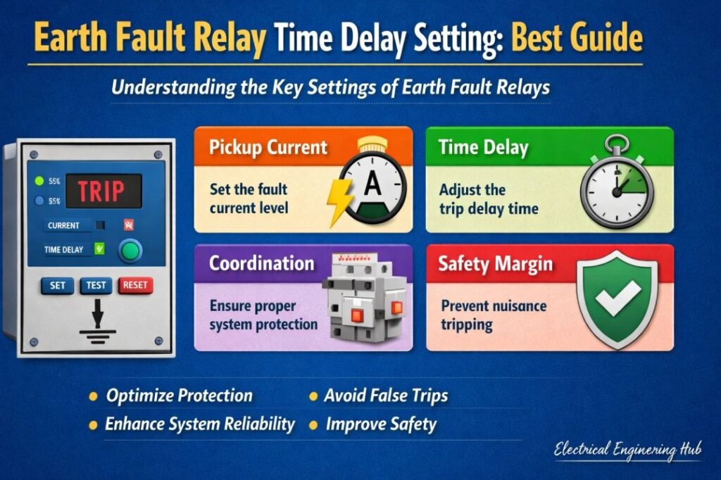
This is where Earth Fault Relay Time Delay Setting becomes important. A properly selected delay provides discrimination between upstream and downstream protection while avoiding unnecessary shutdowns.
What Is Earth Fault Relay Time Delay Setting?
Earth Fault Relay Time Delay Setting is the intentional delay applied between the detection of an earth fault and the relay’s trip command. The delay is normally selected to coordinate the relay with downstream circuit breakers, fuses, or other protective relays.
For example, consider a distribution transformer feeding several outgoing feeders. If an earth fault occurs on one feeder, its feeder protection should normally clear the fault first. The transformer incomer relay should remain closed during this period.
If the incomer relay has no suitable time margin, both breakers may trip. This reduces selectivity and can disconnect healthy circuits unnecessarily.
The time delay therefore forms an important part of a coordinated protection system.
Why Is Time Delay Required in Earth Fault Protection?
A relay does not operate in isolation. Electrical systems usually contain several layers of overcurrent and earth fault protection. Each layer needs enough time to determine whether the fault belongs to its protected zone.
The main reasons for applying a time delay include:
- Maintaining discrimination between protection devices
- Preventing unnecessary upstream breaker operation
- Allowing downstream breakers to clear faults
- Accounting for breaker operating time
- Allowing relay reset and overshoot margins
- Improving continuity of supply
- Supporting selective coordination
A short delay may improve fault-clearing speed but can reduce selectivity. A long delay can improve coordination but may expose cables, transformers, and switchgear to higher thermal and mechanical stress.
The correct value is therefore a balance between speed and coordination.
Factors That Affect Relay Time Delay
Several electrical and protection parameters influence the required delay.
| Factor | Effect on Time Delay |
|---|---|
| Downstream breaker clearing time | Sets the minimum coordination margin |
| Relay operating time | Must be included in grading |
| CT performance | Can affect accurate fault detection |
| Fault current level | Determines relay operating behavior |
| System grounding | Changes earth fault current |
| Relay characteristic | Definite-time or inverse-time behavior affects coordination |
| Breaker interrupting time | Adds to total fault-clearing time |
| Protection hierarchy | Determines required grading margin |
The grounding arrangement is particularly important. Solidly grounded, resistance-grounded, and impedance-grounded systems can have very different earth fault currents.
Definite-Time vs Inverse-Time Earth Fault Protection
Two common approaches are used for earth fault relay operation: definite-time and inverse-time protection.
| Protection Type | Operating Principle | Typical Application |
|---|---|---|
| Definite time | Relay trips after a fixed delay | Simple radial distribution |
| Standard inverse | Higher fault current produces faster operation | General distribution protection |
| Very inverse | Stronger inverse characteristic | Feeders with high fault-current variation |
| Extremely inverse | Very fast operation at high currents | Certain coordination applications |
With definite-time protection, the relay operates after a preset delay once the pickup current is exceeded.
Inverse-time protection behaves differently. As earth fault current increases, relay operating time decreases. This can provide better coordination across systems where fault current changes significantly with location.
How to Calculate Earth Fault Relay Time Delay
A practical coordination calculation starts with the downstream protective device.
The basic relationship can be represented as:
Required relay delay = downstream clearing time + coordination margin
For example, suppose a downstream breaker requires 0.18 seconds to detect and clear an earth fault. If the selected grading margin is 0.20 seconds, the upstream relay should have a delay of approximately:
0.18 + 0.20 = 0.38 seconds
The actual engineering value should then be checked against the relay manufacturer’s operating characteristics and the complete protection coordination study.
| Example Parameter | Value |
|---|---|
| Downstream breaker clearing time | 0.18 s |
| Relay and breaker uncertainty margin | 0.05 s |
| Additional coordination margin | 0.15 s |
| Approximate upstream delay | 0.38 s |
The exact margin should never be selected from a generic rule alone. Modern numerical relays, circuit breakers, CTs, and communication-assisted schemes can require different coordination intervals.
For a complete calculation, see earth fault relay setting calculation and use the fault current, CT ratio, pickup setting, and relay curve together.
Typical Time Grading Between Relays
Protection engineers often create a grading table before finalizing relay settings.
| Protection Level | Example Time Delay | Function |
|---|---|---|
| Outgoing feeder | 0.10–0.20 s | Clears local faults first |
| Transformer incomer | 0.30–0.50 s | Backup for feeder |
| Main distribution relay | 0.50–0.80 s | Backup for incomer |
| Utility or upstream protection | Higher as required | Final backup |
These values are illustrative rather than universal settings. Actual values depend on the equipment, relay technology, system fault level, breaker speed, and applicable utility or project requirements.
Role of CT Ratio in Earth Fault Protection
Current transformers are central to relay protection. The relay measures secondary current and uses it to determine whether the earth fault pickup level has been exceeded.
For example, with a 400/5 A CT, a 100 A primary current corresponds to:
100 × 5 / 400 = 1.25 A secondary
The relay pickup setting must therefore be considered in relation to the CT ratio rather than only the primary system current.
CT saturation can also affect protection performance during high-current faults. A protection study should verify CT accuracy, burden, knee-point requirements where applicable, and transient performance.
Coordination Example
Consider a radial distribution system with an outgoing feeder and an upstream incomer.
| Device | Fault Clearing Time | Coordination Role |
|---|---|---|
| Feeder breaker | 0.15 s | Primary protection |
| Incomer relay | 0.40 s | First backup |
| Main upstream relay | 0.65 s | Second backup |
If the feeder fault occurs, the feeder breaker should clear it first. If the feeder protection fails, the incomer protection should operate after the required grading interval. The main upstream protection provides another backup layer.
This arrangement reduces the possibility of disconnecting the entire distribution system for a fault limited to one feeder.
Common Mistakes When Selecting Relay Delay
Incorrect coordination can result from several common errors.
Setting the delay too low
If the upstream relay operates almost simultaneously with the downstream breaker, selectivity can be lost. Two breakers may trip for the same fault.
Ignoring breaker operating time
Relay operating time is not always the complete fault-clearing time. The circuit breaker opening mechanism and arc interruption time must also be considered.
Using the same delay everywhere
Each protection level should be coordinated with the device below it. Applying identical delays throughout a distribution system rarely provides proper discrimination.
Ignoring minimum fault current
A relay may respond differently to maximum and minimum earth fault currents. Both conditions should be checked during coordination.
Forgetting CT limitations
A CT that saturates during a high-current fault can distort the relay input and affect protection performance.
How to Improve Earth Fault Protection Coordination
A reliable coordination study should consider the complete system rather than one relay in isolation.
Follow these steps:
- Obtain the single-line diagram.
- Identify all protection devices.
- Determine maximum and minimum earth fault currents.
- Verify CT ratios and characteristics.
- Select appropriate relay pickup settings.
- Plot relay time-current curves.
- Add breaker operating times.
- Apply an appropriate grading margin.
- Check phase and earth fault coordination.
- Verify the final settings through testing and commissioning.
For larger systems, protection software can plot time-current characteristic curves and identify areas where coordination margins are inadequate.
Frequently Asked Questions
What is a typical earth fault relay time delay?
There is no single standard delay suitable for every installation. Radial distribution systems may use delays in the range of a few tenths of a second, while upstream backup protection may require longer delays. The final value should come from a protection coordination study.
Why does an earth fault relay need a time delay?
The delay allows downstream protection to clear a fault first. This improves selectivity and prevents unnecessary tripping of upstream breakers.
How is relay time delay calculated?
A basic approach is to add the downstream device’s total clearing time to an appropriate coordination margin. Relay characteristics, breaker speed, CT performance, and system fault levels must also be considered.
Does higher earth fault current reduce relay operating time?
With inverse-time relay characteristics, higher fault current generally results in faster relay operation. Definite-time relays, however, operate after a preset delay once the pickup threshold is exceeded.
Can the same earth fault delay be used for all feeders?
Usually not. Different feeders can have different fault levels, cable lengths, breaker characteristics, and downstream protection. Each protection level should be coordinated with the equipment it backs up.
Final Thoughts
A properly selected Earth Fault Relay Time Delay Setting is essential for achieving selective and dependable electrical protection. The goal is not simply to make the relay trip quickly. The relay must trip quickly enough to limit fault damage while still allowing the downstream protective device to operate first.
The best results come from studying maximum and minimum fault currents, CT characteristics, relay curves, breaker clearing times, and coordination margins together. Once these factors are evaluated, the final relay delay can be selected with much greater confidence.
For engineers working through the complete protection settings, earth fault relay setting calculation provides a useful next step for determining pickup values and coordinating relay operation across multiple protection levels.
Get new guides in your feed. Follow Electrical Insights on LinkedIn for new electrical standards guides, calculators and design tips from Azad Circuit Hub.
#EarthFaultRelayTimeDelaySetting, #EarthFaultRelay, #EarthFaultProtection, #RelaySettings, #ProtectionRelay, #ElectricalProtection, #OvercurrentRelay, #FaultProtection, #RelayCoordination, #ElectricalEngineering