
Overload Relay Setting Calculator | NEC 430.32 & IEC 60947-4-1
Electric motors are designed to operate within a specific current range. When the motor draws excessive current for an extended period, overheating can damage the insulation, reduce efficiency, and shorten equipment life. An overload relay prevents these problems by disconnecting the motor before permanent damage occurs. An Overload Relay Setting Calculator helps electricians, engineers, technicians, and maintenance professionals determine the correct overload relay setting based on the motor’s full-load current (FLC).
Instead of relying on manual calculations, the calculator provides a quick and accurate setting that aligns with manufacturer recommendations and electrical standards. Whether you are commissioning a new motor or replacing an overload relay, using the correct setting improves safety, reliability, and equipment performance.
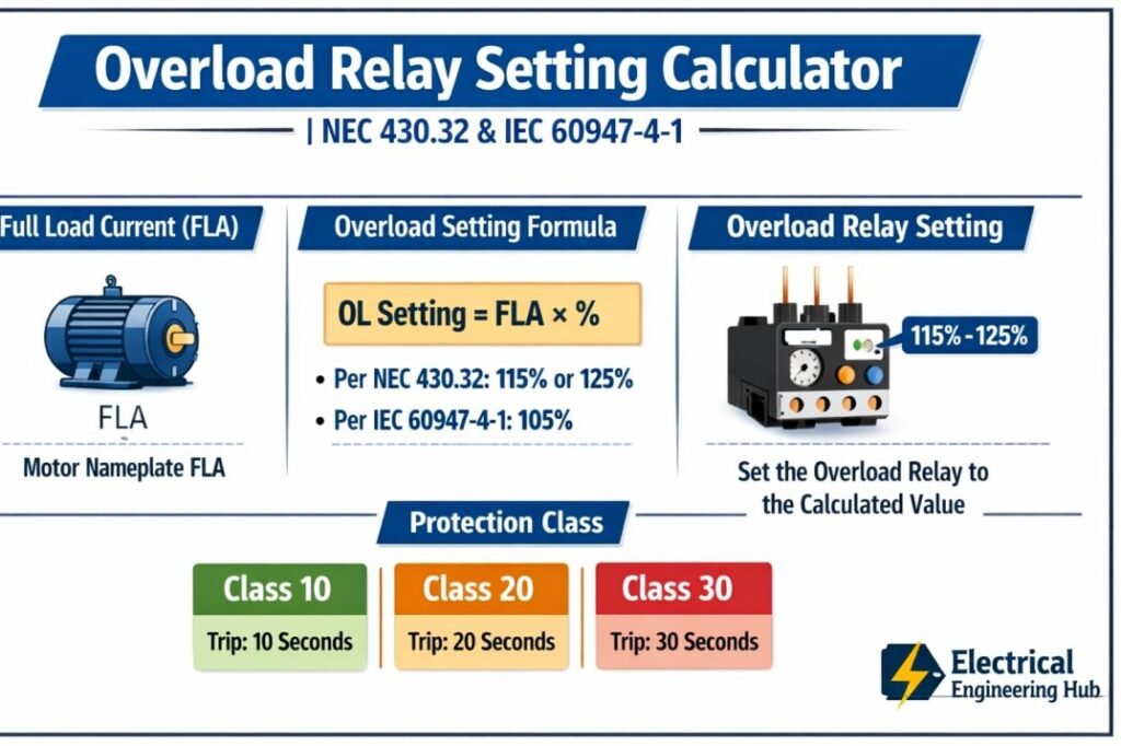
Table of Contents
Table of Contents
Overload Relay Setting Calculator
Overload Relay Setting Calculator
Thermal overload relay pickup setting for NEC 430.32 and IEC 60947-4-1 applications
| Trip Class | Typical Trip Time at 7.2× Setting | Typical Application |
|---|---|---|
| Class 10A | 2 – 10 seconds | Fast starting loads, motor protection close to thermal limit |
| Class 10 | 4 – 10 seconds | Standard duty motors with normal starting time |
| Class 20 | 6 – 20 seconds | Moderate to long starting duty, higher inertia loads |
| Class 30 | 9 – 30 seconds | Long starting duty such as large fans, pumps, compressors |
- Choose the applicable standard — NEC 430.32 for North American installations, or IEC 60947-4-1 for international installations.
- For NEC: enter the motor nameplate full load current, service factor, and temperature rise, then indicate whether the relay holds or trips at the standard setting.
- For IEC: enter the motor nameplate current, the expected motor starting time, and the adjustable range printed on the overload relay dial.
- Review the recommended setting, the gauge position, and the status badge before adjusting the physical relay dial.
- Always verify the final setting against the motor nameplate and the overload relay manufacturer’s instructions before energizing the circuit.
Overload relay settings protect motor windings from sustained overcurrent while allowing normal starting current to pass without nuisance tripping. NEC 430.32 recognizes that motors with a higher service factor or a lower temperature rise have additional thermal margin, which allows a higher standard setting. If the standard setting does not allow the motor to start or carry its load without tripping, the Code permits a single increased setting, provided the motor is not left unprotected against damage from a stalled or locked condition.
IEC 60947-4-1 relays are set directly to the motor nameplate current rather than a percentage of it, since the relay’s internal calibration already accounts for the required thermal margin. The trip class defines how long the relay tolerates high starting current before opening, and should be matched to the motor’s actual starting time so that normal starts are not interrupted while genuine overload and locked rotor conditions are still cleared promptly.
What Is an Overload Relay Setting Calculator?
An Overload Relay Setting Calculator is an electrical tool that calculates the recommended overload relay adjustment using the motor's rated full-load current and service factor. It removes guesswork and helps ensure the relay trips only during genuine overload conditions instead of normal starting currents.
The calculator is commonly used for:
- Motor control panels
- Industrial machines
- Pumps
- Compressors
- Conveyor systems
- HVAC equipment
- Manufacturing plants
- Water treatment facilities
The calculated setting protects the motor while minimizing unnecessary shutdowns.
Why Is Correct Overload Relay Setting Important?
A relay setting that is too low can cause frequent nuisance tripping. A setting that is too high may allow the motor to overheat before the relay operates.
Proper overload relay settings provide several benefits.
| Benefit | Description |
|---|---|
| Motor Protection | Prevents overheating and insulation failure |
| Equipment Reliability | Reduces unexpected downtime |
| Longer Motor Life | Minimizes thermal stress |
| Better Safety | Prevents damage caused by prolonged overload |
| Reduced Maintenance | Lowers repair and replacement costs |
Using an Overload Relay Setting Calculator helps maintain the balance between protection and operational continuity.
How Does an Overload Relay Work?
An overload relay monitors the current flowing through the motor. When the current exceeds the preset value for a certain period, the relay trips and opens the motor starter circuit.
Unlike short-circuit protection devices such as circuit breakers or fuses, overload relays respond to sustained overcurrent rather than instantaneous fault currents.
The relay operates based on the heating effect of current, making it ideal for protecting motors from overload conditions. Follow our complete guide on Overload Relay for Motor
Formula Used by an Overload Relay Setting Calculator
The calculator uses a simple calculation based on the motor full-load current.
| Motor Service Factor | Recommended Setting |
|---|---|
| Service Factor ≥ 1.15 | 125% of Full Load Current |
| Service Factor < 1.15 | 115% of Full Load Current |
The general formula is:
Overload Relay Setting = Full Load Current × Adjustment Factor
Where:
- Adjustment Factor = 1.25 for motors with service factor of 1.15 or greater
- Adjustment Factor = 1.15 for standard motors
Always verify the final setting with the motor manufacturer's recommendations and applicable electrical codes.
Example Calculation
Consider a three-phase induction motor with the following specifications.
| Parameter | Value |
|---|---|
| Rated Power | 15 kW |
| Full Load Current | 28 A |
| Service Factor | 1.15 |
Calculation:
- Overload Relay Setting = 28 × 1.25
- Overload Relay Setting = 35 A
- The overload relay should be adjusted to approximately 35 A.
An Overload Relay Setting Calculator performs this calculation instantly and eliminates manual errors.
Inputs Required for the Calculator
Most overload relay calculators require only a few values.
| Input | Purpose |
|---|---|
| Motor Full Load Current | Primary value for calculation |
| Service Factor | Determines adjustment multiplier |
| Motor Voltage | Reference information |
| Phase Type | Single-phase or three-phase |
| Motor Power | Optional verification |
These inputs are typically available on the motor nameplate.
Output Generated by the Calculator
The calculator provides useful information for engineers and technicians.
| Output | Description |
|---|---|
| Recommended Relay Setting | Calculated overload current |
| Adjustment Factor | Applied multiplier |
| Protection Recommendation | Suitable relay operating point |
| Current Verification | Confirms input values |
This information simplifies relay commissioning and maintenance.
Motor Nameplate Values You Should Check
Before adjusting any overload relay, inspect the motor nameplate carefully.
| Nameplate Item | Importance |
|---|---|
| Rated Voltage | Confirms supply compatibility |
| Full Load Current | Required for relay setting |
| Rated Frequency | Ensures proper operation |
| Power Rating | Identifies motor size |
| Service Factor | Determines adjustment percentage |
| Efficiency | Performance reference |
Never estimate the current value without checking the actual nameplate.
Overload Setting for Motor
The following table provides common examples.
| Motor Full Load Current | Service Factor | Recommended Setting |
|---|---|---|
| 8 A | 1.00 | 9.2 A |
| 12 A | 1.00 | 13.8 A |
| 18 A | 1.15 | 22.5 A |
| 25 A | 1.15 | 31.25 A |
| 40 A | 1.15 | 50 A |
| 60 A | 1.15 | 75 A |
These values are examples only. Actual settings should follow the motor nameplate and applicable standards. Follow our detailed guide on Overload Setting for Motor
Factors That Affect Overload Relay Settings
Several operating conditions influence relay adjustment.
Ambient Temperature
Higher ambient temperatures can increase motor heating and affect overload relay performance.
Motor Duty Cycle
Motors that start and stop frequently may require careful coordination to avoid nuisance tripping.
Service Factor
Motors with higher service factors can safely operate at higher overload settings.
Starting Method
Direct-on-line, star-delta, soft starter, and variable frequency drive systems may require different relay configurations.
Load Characteristics
Heavy starting loads such as crushers, compressors, and conveyors often require careful selection of trip class and relay settings.
Overload Relay Trip Classes
Trip class determines how quickly the relay disconnects the motor during overload conditions.
| Trip Class | Typical Application |
|---|---|
| Class 10 | Standard induction motors |
| Class 20 | Medium starting time applications |
| Class 30 | Heavy-duty motors with long acceleration |
Selecting the proper trip class is just as important as selecting the correct thermal overload relay setting.
Motor Overload Relay Setting Chart
Many users prefer a quick lookup before using a calculator. The table below provides typical overload relay settings based on common motor ratings. Always verify the final value with the motor nameplate full-load current (FLC), the applicable NEC or IEC standard, and the relay manufacturer's recommendations.
| Motor Rating | Approx. Full-Load Current | Typical Overload Relay Setting |
|---|---|---|
| 1 HP (0.75 kW) | 1.8–2.2 A | 2.0 A |
| 5 HP (3.7 kW) | 6.8–7.6 A | 7.2 A |
| 10 HP (7.5 kW) | 13–15 A | 14 A |
If you need a detailed step-by-step method for converting motor power into relay current settings, use our motor overload relay setting guide and calculator, which explains calculations for both HP and kW motors with practical examples.
Overload Relay Amp Lists: Standard Amp Ranges
While an Overload Relay Setting Calculator helps determine the correct setting, engineers also rely on standard overload relay amp lists to choose the right relay adjustment range before commissioning.
Selecting a relay with an appropriate adjustable range improves motor protection and prevents nuisance tripping. For a complete relay selection chart, standard amp ranges, and sizing recommendations, refer to our complete overload relay amp range guide.
| Motor Full Load Current (A) | Typical Overload Relay Range |
|---|---|
| 0.10 – 0.16 | 0.10 – 0.16 A |
| 0.16 – 0.25 | 0.16 – 0.25 A |
| 0.25 – 0.40 | 0.25 – 0.40 A |
| 0.40 – 0.63 | 0.40 – 0.63 A |
| 0.63 – 1.00 | 0.63 – 1.00 A |
| 1.00 – 1.60 | 1.00 – 1.60 A |
Note: Always verify the final overload setting using the motor nameplate and applicable requirements in NEC 430.32 or IEC 60947-4-1.
Overload Relay Rating Chart
An overload relay rating chart helps you quickly match the motor full-load current (FLC) with a suitable adjustable overload relay range before fine-tuning the trip setting using an Overload Relay Setting Calculator. Always verify the selected range against the motor nameplate, NEC 430.32 requirements, or IEC 60947-4-1 recommendations to ensure accurate motor protection.
| Motor Full-Load Current (A) | Typical Overload Relay Range (A) |
|---|---|
| 0.63 – 1.0 | 0.63 – 1.0 |
| 1.0 – 1.6 | 1.0 – 1.6 |
| 1.6 – 2.5 | 1.6 – 2.5 |
| 2.5 – 4.0 | 2.5 – 4.0 |
| 4.0 – 6.3 | 4.0 – 6.3 |
| 6.3 – 10 | 6.3 – 10 |
| 9 – 13 | 9 – 13 |
| 12 – 18 | 12 – 18 |
| 17 – 25 | 17 – 25 |
| 23 – 32 | 23 – 32 |
For a complete list of relay ranges, manufacturer series, and selection guidance, see our overload relay rating table and size guide, which explains how to choose the correct relay range for different motor applications.
Common Mistakes When Setting an Overload Relay
Avoid these common errors.
- Using cable ampacity instead of motor full-load current
- Ignoring the service factor
- Setting the relay above manufacturer recommendations
- Selecting the wrong trip class
- Failing to verify motor nameplate values
- Not testing relay operation after installation
- Assuming identical settings for all motors
These mistakes can lead to unnecessary downtime or inadequate motor protection.
Best Practices for Accurate Relay Settings
Follow these recommendations during installation.
- Read the motor nameplate carefully.
- Verify the measured operating current.
- Use an Overload Relay Setting Calculator before adjusting the relay.
- Follow NEC or IEC requirements where applicable.
- Select the correct relay range.
- Test the motor under normal operating conditions.
- Record the final settings for maintenance documentation.
These practices improve system reliability and simplify future troubleshooting.
Overload Relay vs Circuit Breaker
Many people confuse overload relays with circuit breakers, but they perform different functions.
| Feature | Overload Relay | Circuit Breaker |
|---|---|---|
| Protects Against | Sustained overload | Short circuit and overload |
| Response Time | Time delay | Instantaneous and time delay |
| Motor Protection | Yes | Limited |
| Reset Method | Manual or automatic | Manual reset |
For complete motor protection, both devices are typically used together.
Motor Protection Circuit Breaker vs Overload Relay
Many users of an Overload Relay Setting Calculator also compare overload relays with motor protection circuit breakers (MPCBs). While both protect motors, they perform different functions. An overload relay trips the contactor when the motor draws excessive current over time, whereas an MPCB provides overload, short-circuit, and phase-loss protection in a single device.
| Feature | Overload Relay | Motor Protection Circuit Breaker (MPCB) |
|---|---|---|
| Main Purpose | Overload protection | Overload + short-circuit protection |
| Interrupts Fault Current | No | Yes |
| Used With | Contactor | Can operate independently or with contactor |
| Adjustable Current | Yes | Yes |
For a detailed feature comparison, selection guide, and application examples, read our comparison of Motor Protection Circuit Breaker and Overload Relay. It explains when each device is the better choice for industrial motor protection.
How a Thermal Overload Relay Operates
Many users of an Overload Relay Setting Calculator also want to understand the working principle behind the device before selecting the correct setting. A thermal overload relay protects a motor by sensing the heat produced when excessive current flows for an extended period. Inside the relay, a bimetallic strip bends as it heats up.
When the temperature reaches the preset limit, the strip activates the trip mechanism and opens the control circuit, stopping the motor before overheating damages the windings. After cooling, the relay can be reset manually or automatically, depending on its design.
| Component | Function |
|---|---|
| Bimetallic Strip | Heats and bends in proportion to motor current |
| Trip Mechanism | Opens the control circuit when overload occurs |
| Reset Button | Restores relay operation after cooling |
To learn the complete operating sequence, construction, and trip characteristics, read our guide on how a thermal overload relay operates, which explains the internal working with practical examples.
How to Select Overload Relay for Motor
Many users of an Overload Relay Setting Calculator also need guidance on choosing the correct relay before calculating the setting. Relay selection depends on the motor's full-load current (FLC), service factor, starting method, and trip class. Select a relay with an adjustable current range that includes the motor's nameplate FLC.
For applications with long starting times, choose a higher trip class such as Class 20 or Class 30. Always verify the manufacturer's compatibility with the motor starter and follow NEC 430.32 or IEC 60947-4-1 requirements.
| Selection Factor | Recommendation |
|---|---|
| Motor Full-Load Current | Adjustable range should include the FLC |
| Trip Class | Class 10, 20, or 30 based on starting time |
| Motor Starting Method | DOL, Star-Delta, Soft Starter, or VFD compatible |
| Standard | NEC 430.32 or IEC 60947-4-1 |
For a complete step-by-step guide, read our motor overload relay selection guide, which explains relay sizing, trip class selection, and practical examples for different motor applications.
Where an Overload Relay Setting Calculator Is Used
The calculator is valuable across many industries.
| Industry | Typical Applications |
|---|---|
| Manufacturing | Production machinery |
| Water Treatment | Pumps and blowers |
| Oil and Gas | Compressors and motors |
| Mining | Conveyors and crushers |
| HVAC | Chillers and air handling units |
| Agriculture | Irrigation pumps |
| Commercial Buildings | Ventilation systems |
Proper overload settings reduce equipment failures across these applications.
Frequently Asked Questions
Can I set the overload relay equal to the motor current?
It is generally better to follow the service factor and manufacturer recommendations instead of using only the rated current.
Does the calculator replace manufacturer instructions?
No. The calculator provides a recommended value, but the motor manufacturer's data should always take priority.
Can overload relays protect against short circuits?
No. Overload relays protect against prolonged overcurrent. Short-circuit protection requires a fuse or circuit breaker.
Should I use the nameplate current or measured current?
The motor nameplate full-load current should normally be used unless the manufacturer specifies otherwise.
Related Tools & Guides
Conclusion
An Overload Relay Setting Calculator simplifies one of the most important tasks in motor protection. By calculating the proper relay adjustment using the motor's full-load current and service factor, it helps prevent overheating, unexpected failures, and costly downtime.
Whether you work in industrial maintenance, electrical design, or motor commissioning, using the calculator improves accuracy and ensures dependable motor protection. For the best results, always verify the calculated setting against the motor nameplate, manufacturer documentation, and applicable NEC or IEC requirements before placing the motor into service.
Get new guides in your feed. Follow Electrical Insights on LinkedIn for new electrical standards guides, calculators and design tips from Azad Circuit Hub.
OverloadRelaySettingCalculator, #MotorProtection, #OverloadRelay, #ElectricalEngineering, #MotorControl, #RelaySettings, #ElectricalCalculator, #IndustrialAutomation, #PowerSystems, #ElectricalSafety
Overload Relay Setting Calculator | NEC 430.32 & IEC 60947-4-1
Overload Relay Setting Calculator helps you determine the correct overload relay setting for three-phase motors. Learn motor full-load current calculations, relay adjustment methods, NEC/IEC guidelines, and practical examples to ensure reliable motor protection.
Price Currency: USD
Operating System: Web Browser
Application Category: UtilitiesApplication
