
Overload Setting for Motor: Complete Guide to Correct Relay Adjustment
Electric motors are one of the most valuable assets in industrial and commercial electrical systems. A properly adjusted overload relay protects the motor from excessive current, overheating, and premature failure. Incorrect settings can lead to unnecessary trips or serious motor damage.
Understanding the correct Overload Setting for Motor helps maintenance engineers, electricians, and plant operators improve equipment reliability while reducing downtime. This guide explains how overload protection works, how to calculate the correct setting, common mistakes to avoid, and practical examples for different motor applications.
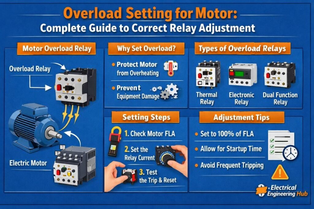
Table of Contents
Table of Contents
What Is Overload Protection for a Motor?
An overload relay is a protective device that disconnects a motor when it draws more current than its rated capacity for an extended period. Unlike a short-circuit protection device, an overload relay allows temporary starting current but reacts to sustained overcurrent conditions.
Motor overload protection prevents:
- Motor winding overheating
- Insulation failure
- Reduced motor lifespan
- Production downtime
- Expensive repair costs
The overload relay is normally installed together with a motor starter or motor control center (MCC).
Why Correct Overload Setting Matters
The correct Overload Setting for Motor ensures the relay trips only when necessary while allowing normal motor operation.
A setting that is too low may cause frequent nuisance tripping during startup or temporary load changes.
A setting that is too high may allow excessive heating before the relay operates, increasing the risk of winding damage.
The objective is to balance protection with reliable operation.
Motor Nameplate Information Required
Before adjusting any overload relay, collect the motor nameplate data.
| Parameter | Example |
|---|---|
| Rated Voltage | 415 V |
| Rated Current (FLC) | 18.5 A |
| Frequency | 50 Hz |
| Power | 11 kW |
| Power Factor | 0.86 |
| Efficiency | 91% |
| Service Factor | 1.15 |
The rated full-load current (FLC) is the most important value for overload adjustment.
Basic Formula for Overload Setting
The general calculation is straightforward.
Overload Setting = Motor Full Load Current × Setting Factor
The setting factor depends on the motor service factor, operating conditions, and applicable electrical standards. Use our online tool for accurate settings Overload Relay Setting Calculator
Recommended Overload Setting for Motor
The following table provides commonly used settings.
| Motor Condition | Recommended Setting |
|---|---|
| Service Factor 1.15 or higher | 125% of FLC |
| Service Factor below 1.15 | 115% of FLC |
| Continuous duty motor | As per manufacturer recommendation |
| Variable Frequency Drive (VFD) motor | Follow VFD settings and manufacturer guidelines |
Always verify local electrical code requirements before final adjustment.
Example Calculation
Consider the following motor.
| Motor Specification | Value |
|---|---|
| Rated Power | 15 kW |
| Rated Voltage | 415 V |
| Full Load Current | 28 A |
| Service Factor | 1.15 |
Calculation:
Overload Setting = 28 × 1.25
Overload Setting = 35 A
The overload relay should be adjusted to approximately 35 A if permitted by the relay range and manufacturer recommendations.
Factors That Affect Overload Setting for Motor
Several operating conditions influence the final relay adjustment.
Ambient Temperature
High ambient temperatures increase motor heating. Some electronic overload relays compensate automatically, while thermal overload relays may require adjustment.
Motor Starting Time
Motors with long acceleration periods need overload relays that tolerate extended starting current without nuisance trips.
Load Characteristics
Constant-load equipment such as pumps and compressors typically requires standard settings, while variable-load equipment may need application-specific adjustments.
Motor Duty Cycle
Motors operating continuously generate more heat than intermittent-duty motors, making proper thermal protection essential.
Manufacturer Recommendations
Always compare calculated values with the motor manufacturer’s instructions.
Thermal vs Electronic Overload Relays
Different relay technologies offer different levels of protection.
| Feature | Thermal Relay | Electronic Relay |
|---|---|---|
| Accuracy | Moderate | High |
| Temperature Compensation | Limited | Excellent |
| Adjustable Trip Class | Limited | Multiple options |
| Communication | No | Often available |
| Maintenance | Low | Low |
Electronic overload relays provide better accuracy and additional motor protection features in modern industrial installations.
Common Trip Classes
Trip class defines how quickly an overload relay disconnects the motor during overload conditions.
| Trip Class | Typical Application |
|---|---|
| Class 10 | Pumps, fans, conveyors |
| Class 20 | Heavy-duty starting loads |
| Class 30 | High inertia motors |
Selecting the proper trip class is as important as choosing the correct current setting.
Common Mistakes During Relay Adjustment
Avoid these common errors during installation.
- Using cable current instead of motor full-load current
- Ignoring the service factor
- Copying settings from another motor
- Not considering ambient temperature
- Choosing the wrong trip class
- Skipping relay testing after adjustment
These mistakes can reduce protection effectiveness and shorten motor life.
How to Set an Overload Relay
Follow these practical steps.
- Read the motor nameplate.
- Identify the full-load current.
- Confirm the service factor.
- Select the correct trip class.
- Calculate the relay setting.
- Adjust the overload dial or electronic setting.
- Perform a functional test.
- Monitor motor operation after commissioning.
A documented commissioning process helps maintain consistency across multiple motors.
Overload Protection in Different Applications
Different industries require slightly different approaches.
| Application | Typical Recommendation |
|---|---|
| Water Pumps | Class 10 relay |
| HVAC Fans | Standard overload setting |
| Air Compressors | Thermal monitoring recommended |
| Crushers | Higher trip class due to heavy starting |
| Conveyor Systems | Standard relay with proper FLC setting |
Each application should be evaluated according to its operating profile.
Relationship Between Overload Relay and Circuit Breaker
Many people confuse overload relays with circuit breakers.
| Overload Relay | Circuit Breaker |
|---|---|
| Protects motor from overheating | Protects against short circuits |
| Responds to sustained overload | Responds to fault current |
| Installed with motor starter | Installed in power distribution panel |
Both devices work together to provide complete motor protection.
Testing the Overload Relay
Testing confirms the relay will operate correctly during actual overload conditions.
Common testing methods include:
- Primary current injection
- Secondary injection testing
- Functional trip testing
- Thermal simulation
- Electronic relay diagnostics
Routine testing improves system reliability and helps identify calibration issues before failures occur.
Best Practices for Reliable Motor Protection
Following industry best practices improves motor performance and minimizes unexpected shutdowns.
- Use the motor nameplate full-load current for calculations.
- Select the correct relay range.
- Follow manufacturer recommendations.
- Inspect relay settings during preventive maintenance.
- Test overload protection after installation.
- Replace damaged or outdated overload relays.
- Record all relay settings for maintenance history.
Proper documentation simplifies troubleshooting and future maintenance activities.
Related Tools & Guides
- Overload Relay Setting Calculator according to NEC 430.32 & IEC 60947-4-1
- Differences in Bimetal Overload and Ambient-Compensated Overload Relays
- Overload Relay for Motor
Conclusion
Selecting the correct Overload Setting for Motor is essential for protecting motors against overheating while maintaining uninterrupted operation. The relay should always be adjusted using the motor’s rated full-load current, service factor, operating conditions, and applicable standards.
Accurate settings reduce nuisance tripping, extend motor life, and improve overall system reliability. Regular inspection, testing, and proper documentation ensure that overload protection continues to perform effectively throughout the motor’s service life.
Related Tool: If you need to determine the correct relay adjustment automatically, use our Motor Overload Setting Calculator to calculate the recommended overload setting based on your motor’s full-load current and service factor.
Get new guides in your feed. Follow Electrical Insights on LinkedIn for new electrical standards guides, calculators and design tips from Azad Circuit Hub.
#OverloadSettingForMotor, #MotorProtection, #OverloadRelay, #MotorRelaySetting, #ElectricalEngineering, #MotorControl, #IndustrialAutomation, #ElectricalSafety, #PowerSystems, #MotorMaintenance

Just a smiling visitor here to share the love (:, btw outstanding style.