
ESP32 Pinout: GPIO Pin Diagram, Functions & Pin Guide
The ESP32 pinout has 34 GPIO pins on the chip. The most common module, the ESP32-WROOM-32, has 38 pads, of which 26 are usable GPIOs, and the popular DevKit boards break out 25 to 30 of them. This guide gives you the pin diagram first, then a complete GPIO table from GPIO0 to GPIO39, and the rules that decide whether a pin works: input-only pins, ADC2 and Wi-Fi, strapping pins, flash pins and default I2C, SPI and UART pins.
Quick answers
- GPIO pins: 34 on the chip, 26 usable on the ESP32-WROOM-32 module, 25 on the 30-pin DevKit V1
- Input-only pins: GPIO34, 35, 36 (VP) and 39 (VN)
- Do not use: GPIO6 to GPIO11 (internal flash)
- ADC with Wi-Fi: use ADC1 pins GPIO32, 33, 34, 35, 36, 39
- Default I2C: SDA GPIO21, SCL GPIO22
- Default SPI (VSPI): SCK GPIO18, MISO GPIO19, MOSI GPIO23, CS GPIO5
- UART2: RX GPIO16, TX GPIO17
- Logic level: 3.3 V only, not 5 V tolerant
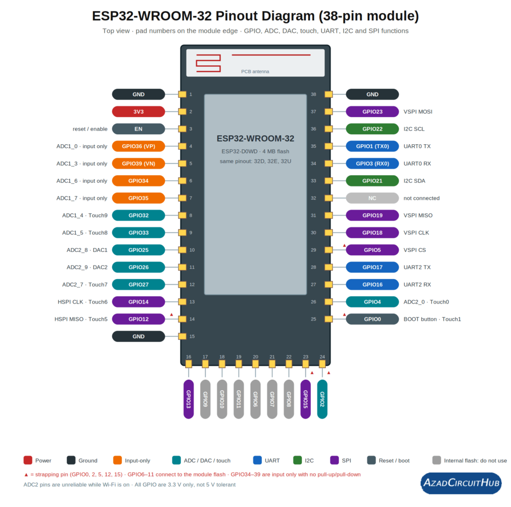
Table of Contents
Table of Contents
ESP32 Pinout Diagram: ESP32-WROOM-32 Module
The diagram shows the bare ESP32-WROOM-32 module. Pads are numbered 1 to 38, starting at the top-left, running down the left side, along the bottom, and up the right side. The antenna is at the top.
Things to notice:
- 26 usable GPIOs: GPIO0, 1, 2, 3, 4, 5, 12, 13, 14, 15, 16, 17, 18, 19, 21, 22, 23, 25, 26, 27, 32, 33, 34, 35, 36 and 39.
- Six pads are the internal flash (GPIO6, 7, 8, 9, 10, 11). Do not connect anything to them.
- Pad 32 is not connected (NC).
- Several GND pads: pads 1, 15 and 38, plus the exposed ground pad under the module.
- GPIO37 and GPIO38 exist on the ESP32 chip but are not broken out on this module.
For the module’s variants, pin-by-pin details and datasheet notes, see the ESP32 WROOM pinout guide.
ESP32 Pin Count: Chip, Module and Dev Board
| Item | Pins | GPIOs available |
|---|---|---|
| ESP32 chip (QFN48) | 48 | 34 |
| ESP32-WROOM-32 module | 38 pads | 26 usable (plus 6 flash pins you cannot use) |
| 30-pin dev board (DevKit V1) | 30 | 25 (GPIO0 is the BOOT button, not on the header) |
| 38-pin dev board (DevKitC, NodeMCU-32S and clones) | 38 | about 26 to 28, depending on the board |
The exact number depends on the board, so always check the silkscreen of your own board.
Which ESP32 Board Do You Have?
The chip and module share the same GPIO functions, but each board arranges the pins differently. Use this table to find the right pin diagram:
| Your board or module | Pin layout guide |
|---|---|
| ESP32-WROOM-32, WROOM-32D, WROOM-32E, WROOM-32U, ESP32S module | ESP32 WROOM pinout |
| ESP32 DevKit V1 (30-pin) | ESP32 DevKit V1 pinout diagram |
| ESP32 Dev Module (Arduino IDE board setting) and generic 38-pin boards | ESP32 Dev Module pinout |
| ESP32 DevKit V1 circuit and design | ESP32 DevKit V1 schematic |
| DevKit V1 specs, dimensions and datasheet | ESP32 DevKit V1 guide |
| Chip specs and variants | ESP32 specs |
| ESP8266 boards | ESP8266 pinout |
Boards from Elegoo, ideaspark, AI-Thinker and other makers usually copy the 30-pin or 38-pin DevKit layout, but some put an OLED, LED or button on particular GPIOs. Match the silkscreen labels on your board against the tables below.
ESP32 GPIO Table (GPIO0 to GPIO39)
This table lists every usable GPIO. “RTC” means the pin can wake the ESP32 from deep sleep.
| GPIO | Type | ADC / DAC | Touch | RTC | Notes |
|---|---|---|---|---|---|
| GPIO0 | In/Out | ADC2_1 | T1 | Yes | Strapping pin. BOOT button; LOW at reset enters flash mode. Outputs PWM at boot |
| GPIO1 | In/Out | none | none | No | TX0, UART0 transmit. Used by USB serial and the boot log |
| GPIO2 | In/Out | ADC2_2 | T2 | Yes | Strapping pin. Onboard LED on many boards |
| GPIO3 | In/Out | none | none | No | RX0, UART0 receive. Used by USB serial |
| GPIO4 | In/Out | ADC2_0 | T0 | Yes | General purpose, a good choice |
| GPIO5 | In/Out | none | none | No | Strapping pin. VSPI CS. Outputs PWM at boot |
| GPIO6 to GPIO11 | none | none | none | No | Connected to the internal flash. Do not use |
| GPIO12 | In/Out | ADC2_5 | T5 | Yes | Strapping pin. HIGH at boot can stop the board booting. HSPI MISO |
| GPIO13 | In/Out | ADC2_4 | T4 | Yes | HSPI MOSI |
| GPIO14 | In/Out | ADC2_6 | T6 | Yes | HSPI CLK. Outputs PWM at boot |
| GPIO15 | In/Out | ADC2_3 | T3 | Yes | Strapping pin. HSPI CS. Outputs PWM at boot |
| GPIO16 | In/Out | none | none | No | UART2 RX. Used by PSRAM on WROVER modules |
| GPIO17 | In/Out | none | none | No | UART2 TX. Used by PSRAM on WROVER modules |
| GPIO18 | In/Out | none | none | No | VSPI CLK (SCK) |
| GPIO19 | In/Out | none | none | No | VSPI MISO |
| GPIO21 | In/Out | none | none | No | Default I2C SDA |
| GPIO22 | In/Out | none | none | No | Default I2C SCL |
| GPIO23 | In/Out | none | none | No | VSPI MOSI |
| GPIO25 | In/Out | ADC2_8, DAC1 | none | Yes | 8-bit DAC output |
| GPIO26 | In/Out | ADC2_9, DAC2 | none | Yes | 8-bit DAC output |
| GPIO27 | In/Out | ADC2_7 | T7 | Yes | General purpose |
| GPIO32 | In/Out | ADC1_4 | T9 | Yes | ADC1, safe with Wi-Fi |
| GPIO33 | In/Out | ADC1_5 | T8 | Yes | ADC1, safe with Wi-Fi |
| GPIO34 | Input only | ADC1_6 | none | Yes | No internal pull-up or pull-down |
| GPIO35 | Input only | ADC1_7 | none | Yes | No internal pull-up or pull-down |
| GPIO36 (VP) | Input only | ADC1_0 | none | Yes | No internal pull-up or pull-down |
| GPIO39 (VN) | Input only | ADC1_3 | none | Yes | No internal pull-up or pull-down |
GPIO20, 24 and 28 to 31 are not available on the ESP32-WROOM-32, and GPIO37 and 38 are not broken out. If you are looking for a specific pin such as GPIO23 or GPIO25, find its row above and check the default role before you reuse it.
Input-Only Pins and Output Pins
Input-only pins: GPIO34, 35, 36 and 39 can read signals but cannot drive an output, and they have no internal pull-up or pull-down resistors. Add an external resistor when you use them with buttons or open-drain sensors.
Pins you can use as digital outputs: every other usable GPIO. Good choices are GPIO4, 13, 16, 17, 18, 19, 21, 22, 23, 25, 26, 27, 32 and 33 (GPIO16 and 17 are not free on WROVER modules).
Each GPIO outputs 3.3 V and is not 5 V tolerant. Use a level shifter or a resistor divider for 5 V signals. Keep the current per pin to a modest level (about 20 mA is a common guideline; check the Espressif datasheet for the absolute limit), and drive relays, motors and LED strips through a transistor, MOSFET or driver.
ESP32 ADC and DAC Pins
The ESP32 has 18 analog input channels across two 12-bit ADCs. On the ESP32-WROOM-32 module you can reach 16 of them.
| ADC | GPIO pins |
|---|---|
| ADC1 | GPIO32, 33, 34, 35, 36 (VP), 39 (VN) |
| ADC2 | GPIO0, 2, 4, 12, 13, 14, 15, 25, 26, 27 |
- Use ADC1 whenever Wi-Fi is on. ADC2 is shared with the Wi-Fi driver, and analogRead() on ADC2 pins is not reliable while Wi-Fi is active.
- The input range is roughly 0 to 3.3 V. It is not perfectly linear, so use calibration or average several samples when accuracy matters.
- DAC: GPIO25 (DAC1) and GPIO26 (DAC2) are two 8-bit analog outputs.
ESP32 Touch Pins
The ESP32 has 10 capacitive touch inputs: T0 on GPIO4, T1 on GPIO0, T2 on GPIO2, T3 on GPIO15, T4 on GPIO13, T5 on GPIO12, T6 on GPIO14, T7 on GPIO27, T8 on GPIO33 and T9 on GPIO32.
ESP32 PWM Pins
Any output-capable GPIO can produce PWM through the LEDC peripheral, which has 16 independent channels. There are no fixed PWM pins. Avoid the input-only pins GPIO34, 35, 36 and 39, and be careful with GPIO5, 14 and 15, which output a short PWM signal at boot.
The Arduino API for LEDC changed between core versions, so follow the example for the version you use in the ESP32 Arduino PWM example.
ESP32 I2C, SPI and UART Pins
The ESP32 has a GPIO matrix, so most peripheral signals can be routed to almost any pin. The defaults below are what libraries use unless you change them.
| Interface | Signal | Default GPIO |
|---|---|---|
| I2C | SDA | GPIO21 |
| I2C | SCL | GPIO22 |
| SPI (VSPI) | MOSI | GPIO23 |
| SPI (VSPI) | MISO | GPIO19 |
| SPI (VSPI) | SCK | GPIO18 |
| SPI (VSPI) | CS | GPIO5 |
| SPI (HSPI) | MOSI / MISO / SCK / CS | GPIO13 / 12 / 14 / 15 |
| UART0 | TX / RX | GPIO1 / GPIO3 (USB serial) |
| UART2 | TX / RX | GPIO17 / GPIO16 |
UART1 has no safe default on most boards, so assign your own pins. You can also move I2C, SPI and UART to other free GPIOs:
Wire.begin(21, 22);                          // SDA, SCL
SPI.begin(18, 19, 23, 5);                    // SCK, MISO, MOSI, SS
Serial2.begin(9600, SERIAL_8N1, 16, 17);     // baud, config, RX, TX
Serial1.begin(9600, SERIAL_8N1, 25, 26);     // UART1 on your own pins
The ESP32 also has two I2S controllers for audio, which can use almost any GPIO, and a built-in CAN controller (called TWAI) that can use any two pins. For CAN you still need an external transceiver such as the SN65HVD230.
For a hands-on example of reading quadrature signals on these pins, see the ESP32 rotary encoder example.
Strapping Pins, GPIO0 and Boot Behaviour
The ESP32 reads GPIO0, 2, 5, 12 and 15 when it resets, and their level decides how it boots.
- GPIO0: LOW at reset puts the chip into flash (download) mode. It is connected to the BOOT button. On the 30-pin DevKit V1 it is not on the header, so hold BOOT while uploading if the board needs it.
- GPIO2: must not be held in the wrong state during flashing. It drives the onboard LED on many boards.
- GPIO12: a HIGH level at boot selects the wrong flash voltage on most modules and can stop the board from booting. Do not wire it to a circuit that pulls it high at power-up.
- GPIO5 and GPIO15: affect boot messages and timing. GPIO5, 14 and 15 also output a short PWM signal at boot, which can briefly trigger relays.
- GPIO1 and GPIO3: carry USB serial and the boot log. Avoid them for other signals while using the Serial Monitor.
- GPIO6 to GPIO11: internal flash, never usable.
- GPIO16 and GPIO17: reserved for PSRAM on ESP32-WROVER modules.
Safe general-purpose pins on a typical board: GPIO4, 13, 16, 17, 18, 19, 21, 22, 23, 25, 26, 27, 32 and 33.
ESP32 Power Pins: 3V3, EN, VIN and GND
- 3V3: the 3.3 V supply. The ESP32 works from about 3.0 to 3.6 V.
- EN: chip enable and reset. Pulling it LOW resets the ESP32. Dev boards add a pull-up resistor and a reset button.
- VIN or 5V: present on dev boards, not on the bare module. It takes 5 V and feeds the onboard 3.3 V regulator. When the board is powered over USB, the pin also carries the USB 5 V.
- GND: the bare module has several ground pads (1, 15, 38 and the exposed pad). The 30-pin DevKit V1 has two GND pins and 38-pin boards have three.
The ESP32 has no separate RST pin. The EN pin does the reset job.
ESP32 Pin Spacing and Size
Dev boards use standard 2.54 mm (0.1 inch) header pitch, so they fit breadboards and perfboard. The bare ESP32-WROOM-32 module has castellated pads at 1.27 mm pitch, so it needs a custom PCB or an adapter board. Most 30-pin and 38-pin dev boards are wide enough to cover most of a standard half-size breadboard, so check the free rows before wiring.
ESP32 Module Variants With the Same Pinout
| Module | Notes |
|---|---|
| ESP32-WROOM-32 | The reference 38-pad module in this guide |
| ESP32-WROOM-32D | Same pinout, ESP32-D0WD chip |
| ESP32-WROOM-32E | Same pinout, newer chip revision |
| ESP32-WROOM-32U | Same pinout, U.FL connector for an external antenna instead of the PCB antenna |
| ESP32S (ESP-32S) | AI-Thinker style module, same pinout. Also the name of the NodeMCU-32S board |
| ESP32-WROVER | Adds PSRAM. GPIO16 and 17 are used internally |
See the ESP32 WROOM pinout guide for the WROOM-32U, ESP32S and WROOM-32 details.
Best ESP32 Pins for Common Tasks
| Task | Suggested pins |
|---|---|
| LEDs, relays, digital outputs | GPIO4, 13, 16, 17, 18, 19, 21, 22, 23, 25, 26, 27, 32, 33 |
| Buttons and digital inputs | GPIO4, 13, 16, 17, 18, 19, 21, 22, 23, 25, 26, 27, 32, 33 (or input-only 34, 35, 36, 39 with an external pull-up) |
| Analog sensors with Wi-Fi | GPIO32, 33, 34, 35, 36, 39 |
| I2C displays and sensors | SDA GPIO21, SCL GPIO22 |
| SPI displays and SD cards | MOSI GPIO23, MISO GPIO19, SCK GPIO18, CS GPIO5 |
| UART modules (GPS, GSM, LoRa) | TX GPIO17, RX GPIO16 |
| DAC output | GPIO25, GPIO26 |
| Capacitive touch | GPIO4, 12, 13, 14, 15, 27, 32, 33 |
Need More ESP32 GPIO Pins?
If you run out of pins, add more instead of using the flash or strapping pins. An I2C GPIO expander such as the MCP23017 or PCF8574 adds 8 to 16 digital pins over just GPIO21 and GPIO22. A 74HC595 shift register adds outputs, and a 74HC4051 analog multiplexer adds analog inputs on one ADC1 pin.
Getting Started: Programming the ESP32 and Its Specs
To upload code you need the ESP32 board package in the Arduino IDE. Follow the Arduino IDE setup guide for the ESP32 for the board package, port and driver steps. For processor speed, memory, radio and the ESP32 family variants, see the ESP32 specs.
ESP32 Pinout vs ESP8266 Pinout
The ESP8266 has fewer usable pins and fewer features, so pin choices are tighter.
| Feature | ESP32 | ESP8266 |
|---|---|---|
| GPIOs on a typical board | 25 to 30 | about 9 to 11 |
| Analog inputs | up to 16 (two ADCs) | one (A0) |
| DAC and touch pins | yes | no |
| Bluetooth | yes | no |
| Logic level | 3.3 V | 3.3 V |
For the ESP8266 pin diagrams, see the ESP8266 pinout guide, the ESP12F pinout (the same module is also sold as ESP8266MOD), the NodeMCU pinout and the ESP8266MOD guide, which covers ESP8266MOD vs ESP8266EX. If you are choosing between the two chips, read the ESP12F vs ESP32 comparison. The WLED setup guide for ESP8266 is a good first LED project, and WLED also runs on the ESP32.
ESP32 vs Arduino and Raspberry Pi Pico Pins
An Arduino Uno works at 5 V logic, while the ESP32 works at 3.3 V, so signals between them need level shifting. The Uno has fewer pins and no Wi-Fi or Bluetooth. See the Arduino UNO R3 pinout to compare. For a broader comparison with the Raspberry Pi Pico and other boards, see Raspberry Pi vs Arduino, ESP32, BeagleBone and Pico. If you want Bluetooth on a board without it, the HC-05 Bluetooth module guide covers the wiring.
ESP32 Project Ideas to Try With These Pins
Once your pins are chosen, explore ESP32 project ideas from beginner to advanced. For smart-home builds, start with the top ESP-based smart home projects, the ESP12F relay build and a comparison of the best WiFi modules for smart home projects.
ESP32 Pinout FAQ
How many GPIO pins does the ESP32 have?
The ESP32 chip has 34 GPIO pins. On the ESP32-WROOM-32 module 26 are usable (six more connect to the flash), and the 30-pin DevKit V1 exposes 25.
Which ESP32 pins are input only?
GPIO34, GPIO35, GPIO36 (VP) and GPIO39 (VN). They cannot be outputs and have no internal pull-up or pull-down resistors.
Which ESP32 pins can I use for analog input with Wi-Fi?
The ADC1 pins: GPIO32, 33, 34, 35, 36 and 39. ADC2 pins are unreliable while Wi-Fi is active.
Which pins can I use for PWM?
Any output-capable GPIO, through the LEDC peripheral with 16 channels. That excludes the input-only pins and the flash pins.
What are the default I2C, SPI and UART pins?
I2C: GPIO21 (SDA) and GPIO22 (SCL). SPI (VSPI): GPIO18 (SCK), GPIO19 (MISO), GPIO23 (MOSI), GPIO5 (CS). UART2: GPIO16 (RX) and GPIO17 (TX). UART0 on GPIO1 and GPIO3 is used by USB serial.
What does GPIO0 do on the ESP32?
GPIO0 is a strapping pin. If it is LOW when the chip resets, the ESP32 enters flash mode. It is connected to the BOOT button, and it is not on the header of the 30-pin DevKit V1.
Which ESP32 pins should I avoid?
GPIO6 to 11 (flash), GPIO1 and 3 (USB serial), and the strapping pins GPIO0, 2, 5, 12 and 15 unless you control their level at boot. GPIO16 and 17 are also unavailable on WROVER modules.
Is the ESP32 5 V tolerant?
No. All GPIOs are 3.3 V. Use a level shifter or a voltage divider for 5 V signals.
How do I connect an FTDI adapter to the ESP32 WROOM?
Connect FTDI TXD to RX0 (GPIO3), FTDI RXD to TX0 (GPIO1), GND to GND and the 3.3 V supply to 3V3. To flash, hold GPIO0 LOW (the BOOT button) while pulsing EN to reset the chip.
What is the ESP32 CAN bus pinout?
The ESP32’s CAN controller (TWAI) can use any two free GPIOs for TX and RX, so there are no fixed pins. Connect them to a CAN transceiver such as the SN65HVD230. GPIO21 and 22 are the default I2C pins, not CAN pins.
How many GND pins does the ESP32 have?
The bare WROOM-32 module has several ground pads (pins 1, 15, 38 and an exposed pad). The 30-pin DevKit V1 has two GND pins and 38-pin boards have three.
Conclusion
The ESP32 pinout is flexible, but a few rules decide whether a project works: keep to 3.3 V, use ADC1 pins for analog input with Wi-Fi, treat GPIO34, 35, 36 and 39 as input only, leave GPIO6 to 11 alone and control the strapping pins at boot. Pick your board in the table above for its exact pin diagram, and use the GPIO table when you need to check a specific pin.
Related ESP32 Guides
- ESP32 WROOM pinout
- ESP32 DevKit V1 pinout diagram
- ESP32 DevKit V1 schematic
- ESP32 DevKit V1 guide
- ESP32 specs
- Arduino IDE setup for the ESP32
- ESP32 PWM example
- ESP32 encoder example
- ESP32 project ideas
References
- Espressif ESP32 datasheet and technical reference manual
- Espressif ESP32-WROOM-32 module datasheet
Technical note: pin availability and labels differ between boards. Confirm them against the silkscreen and documentation of your own board.
Get new guides in your feed. Follow Electrical Insights on LinkedIn for new electrical standards guides, calculators and design tips from Azad Circuit Hub.
