
Phase to Phase Clearance as per IEC 61439: Standard & Chart
What Is Phase to Phase Clearance?
Phase to phase clearance is the minimum safe distance maintained between two energized conductors of different phases in an electrical system. This spacing prevents electrical arcing, short circuits, insulation failure, and flashover under normal and fault conditions.
The required phase to phase distance depends on system voltage, insulation type, environmental conditions, and applicable standards such as IEC, IEEE, or NEC. Proper phase spacing is critical in switchgear, busbars, overhead lines, and cable terminations to ensure safety, reliability, and heat dissipation.
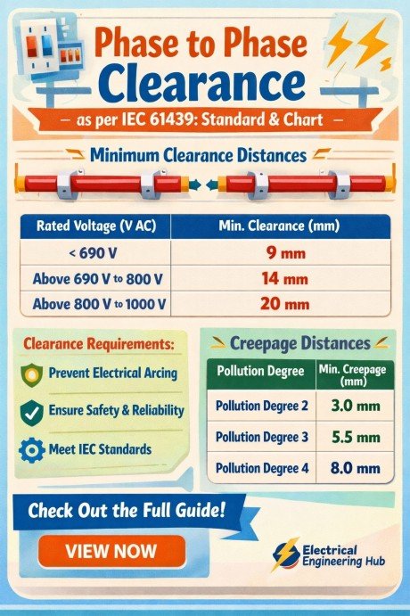
Table of Contents
Table of Contents
In practical installations, phase to phase clearance is not just about avoiding contact—it also accounts for voltage stress, transient surges, and mechanical movement caused by vibration or thermal expansion. Engineers calculate phase spacing based on voltage class and installation type to maintain compliance and reduce electrical hazards.
Phase to Phase Clearance Chart as per IEC 61439
The phase to phase clearance chart below provides a quick reference for the minimum spacing required between energized conductors at different voltage levels. It covers low voltage (LV), medium voltage (MV), high voltage (HV), extra-high voltage (EHV), and ultra-high voltage (UHV) systems commonly used in industrial plants, transmission substations, and utility networks.
These values are based on common IEC 61439, IEC 60071, IEC 62271, IEEE, and utility engineering practices. Actual clearance requirements depend on insulation coordination, altitude, pollution level, switching surges, lightning impulse withstand voltage, enclosure type, and local utility standards.
Phase to Phase Clearance Chart
| Voltage Level | Typical Minimum Phase-to-Phase Clearance | Common Query | Standard Reference |
|---|---|---|---|
| Up to 1 kV | 25–40 mm | LV switchboards | IEC 61439 / NEC |
| 1 kV–11 kV | 75–150 mm | 11kv phase to phase clearance | IEC 62271 |
| 11 kV–33 kV | 150–320 mm | 33kv phase to phase clearance | IEC 60071 |
| 33 kV–66 kV | 320–630 mm | 66 kV phase to phase clearance | IEC 60071 |
| 66 kV–132 kV | 630–1250 mm | 132 kv phase to phase clearance | IEC 60071 / IEEE C37 |
| 132 kV–220 kV | 1250–2100 mm | 220 kv phase to phase clearance | IEC 60071 |
| 220 kV–400 kV | 2100–3500 mm | 400 kV phase to phase clearance | IEC 60071 / Utility Standards |
| 400 kV–765 kV | 3500–6000 mm* | 765 kv phase to phase clearance | IEC 60071 / Utility Standards |
| Above 765 kV (UHV) | Project-specific insulation coordination | UHV transmission | IEC 60071 |
Need the exact clearance for your specific voltage or insulation type?
This chart covers common values, but exact clearance depends on your specific voltage, insulation type, and installation conditions. Use our free Phase to Phase Clearance Calculator to get a precise result in seconds.
Phase to Phase Clearance Chart Voltage-Level
| Voltage | Typical Phase-to-Phase Clearance |
|---|---|
| 11 kV | 75–150 mm |
| 33 kV | 150–320 mm |
| 132 kV | 630–1250 mm |
| 220 kV | 1250–2100 mm |
| 765 kV | 3500–6000 mm (utility/project dependent) |
This phase to phase clearance chart helps engineers perform quick design checks for switchgear, substations, busbar systems, GIS, AIS, and overhead transmission lines. While the values provide a practical engineering reference, final equipment clearances should always be confirmed using IEC 60071 insulation coordination studies, IEC 62271 equipment requirements, manufacturer recommendations, and the applicable utility or grid code before construction or commissioning.
What is IEC 61439 Standard?
The IEC 61439 Standard is the international specification for low-voltage switchgear and controlgear assemblies. Published by the International Electrotechnical Commission (IEC), it defines design verification, construction, testing, and performance requirements to ensure assemblies operate safely under normal and fault conditions.
While this article focuses on phase-to-phase clearance, the standard also covers temperature rise, dielectric strength, short-circuit withstand capability, and enclosure protection. Meeting these requirements helps manufacturers deliver reliable and compliant electrical panels for industrial, commercial, and infrastructure applications.
| Aspect | IEC 61439 Requirement |
|---|---|
| Scope | Low-voltage switchgear and controlgear assemblies |
| Main Focus | Safety, performance, and design verification |
| Covers | Clearance, creepage, temperature rise, short-circuit strength, IP rating |
For a detailed explanation of the complete standard, its structure, testing requirements, and compliance process, read our comprehensive guide on IEC 61439 Standard Explained: Scope, Structure & Requirements. This resource provides a broader understanding beyond clearance values and practical design considerations.
Minimum Electrical Clearance as per IEC 61439
The minimum electrical clearance as per IEC 61439 refers to the shortest air distance required between live conductive parts of different phases or between live parts and earth inside low-voltage switchgear and controlgear assemblies. This clearance ensures safe insulation coordination and prevents flashover during normal operation and transient overvoltages.
According to IEC 61439, the required clearance depends mainly on rated impulse withstand voltage (Uimp), pollution degree, altitude, and insulation type. Higher impulse voltages require larger air gaps to maintain dielectric strength.
Key Factors Affecting Minimum Electrical Clearance
1. Pollution Degree
IEC 61439 classifies environments into pollution degrees, which directly impact insulation performance:
- Pollution Degree 1: Clean, dry environments with minimal contamination
- Pollution Degree 2: Normal industrial and commercial indoor conditions
- Pollution Degree 3: Conductive dust, humidity, or condensation likely
- Pollution Degree 4: Severe industrial or outdoor contamination
Higher pollution levels reduce insulation effectiveness and may require increased spacing.
2. Altitude Correction
At elevations above 2000 meters, air density decreases, lowering dielectric strength. IEC 61439 requires correction factors for clearances at higher altitudes to maintain insulation performance.
3. Insulation Type
Clearance requirements also vary depending on insulation arrangement:
- Functional insulation – basic operational separation
- Basic insulation – protection against electric shock
- Reinforced insulation – higher protection equivalent to double insulation
IEC 61439 Clearance Reference
| Rated Impulse Voltage (Uimp) | Minimum Clearance |
|---|---|
| 1.5 kV | 1.5 mm |
| 2.5 kV | 2.5 mm |
| 4 kV | 3 mm |
| 6 kV | 5.5 mm |
| 8 kV | 8 mm |
| 12 kV | 14 mm |
These values are commonly used in switchboards, MCC panels, and distribution assemblies. For a complete breakdown across IEC standards, voltage classes, and insulation coordination methods, refer to the detailed guide on Minimum Electrical Clearance as per IEC Standards.
Busbar Clearance as per IEC 61439
Busbar clearance as per IEC 61439 refers to the minimum air gap and spacing maintained between busbars of different phases and between busbars and earth inside low-voltage switchgear assemblies. These clearances are essential to prevent phase-to-phase faults, flashover, overheating, and insulation breakdown during normal operation and fault conditions.
IEC 61439 defines busbar clearance requirements based on rated insulation voltage, impulse withstand voltage (Uimp), short-circuit level, pollution degree, and installation altitude. Proper busbar spacing also improves heat dissipation and mechanical stability, especially in high-current panels.
Busbar Spacing Reference Table
The table below provides a quick reference for typical busbar spacing based on system voltage and current rating used in industrial panels and switchboards.
| System Voltage | Current Rating | Typical Phase-to-Phase Busbar Clearance | Standard Reference |
|---|---|---|---|
| 415 V | Up to 400 A | 20 mm – 25 mm | IEC 61439 |
| 415 V | 400 A – 1600 A | 25 mm – 40 mm | IEC 61439 |
| 415 V | 1600 A – 3200 A | 40 mm – 60 mm | IEC 61439 |
| 690 V | Up to 800 A | 30 mm – 40 mm | IEC 61439 |
| 690 V | 800 A – 2500 A | 40 mm – 60 mm | IEC 61439 |
| 690 V | Above 2500 A | 60 mm – 100 mm | IEC 61439 |
| 1000 V | Up to 4000 A | 75 mm – 120 mm | IEC 61439 |
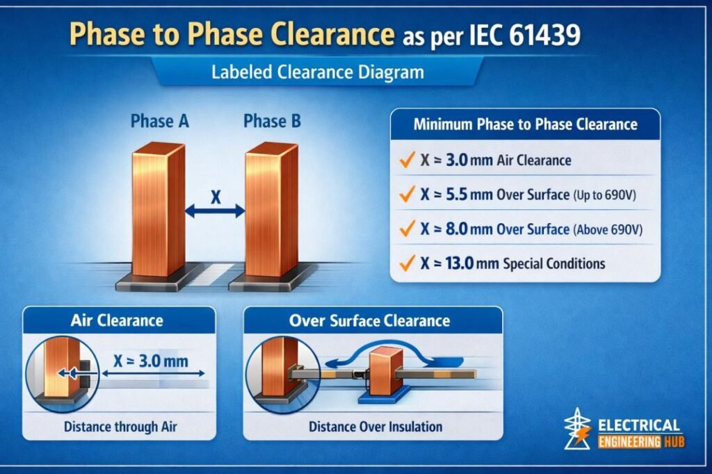
Phase to Phase Clearance Labeled Clearance Diagram
Factors Affecting Busbar Clearance
Voltage Rating
Higher system voltages require larger clearances to withstand transient overvoltages and switching surges.
Current Carrying Capacity
Higher current ratings increase thermal stress, requiring additional spacing for heat dissipation.
Short-Circuit Withstand Strength
Fault currents create strong electromagnetic forces that can cause busbar movement, so extra spacing may be necessary.
Pollution Degree and Environment
Dust, moisture, and contaminants can reduce insulation strength and increase the required clearance.
For exact design values, manufacturers also consider creepage distance, enclosure type, and fault level calculations. For detailed voltage-wise and ampacity-based spacing charts, refer to the complete guide on Busbar Clearance as per IEC 61439.
Factors That Influence Phase to Phase Clearance
Phase to phase clearance is not a fixed value for every electrical installation. The required spacing changes depending on operating conditions, environmental factors, and insulation coordination requirements. Understanding these factors is important for selecting safe conductor spacing and ensuring compliance with IEC and IEEE standards.
1. System Voltage Level
Voltage is the primary factor in determining phase spacing. Higher voltages create stronger electric fields and increase the risk of flashover, which means larger air clearances are required between phases.
For example, a 415V panel may only require a few millimeters of separation, while an 11kV or 33kV system requires significantly greater spacing.
2. Altitude
Air insulation strength decreases at higher altitudes because of lower air density. Above 2000 meters, the dielectric strength of air reduces, making electrical arcing more likely at the same clearance distance.
IEC standards require altitude correction factors to increase phase to phase clearance for high-elevation installations.
3. Pollution Degree
Environmental contamination affects insulation performance. Dust, moisture, chemicals, and conductive particles can create leakage paths and weaken air insulation.
IEC classifies pollution into four categories:
- Pollution Degree 1: Clean and dry
- Pollution Degree 2: Normal indoor industrial use
- Pollution Degree 3: Conductive pollution or condensation likely
- Pollution Degree 4: Severe outdoor or industrial contamination
Higher pollution levels generally require increased clearances.
4. Insulation Material
The type and quality of insulation used around conductors directly influence spacing requirements. Better insulation systems can allow reduced clearances while maintaining safety.
Common insulation types include:
- PVC
- XLPE
- EPR
- Epoxy insulation
Each has different dielectric strength and thermal properties.
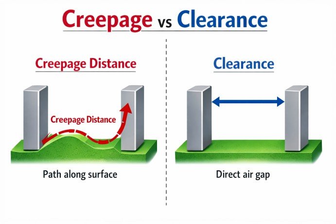
5. Creepage Distance vs Clearance
A common mistake is confusing creepage distance with clearance.
| Parameter | Definition |
|---|---|
| Clearance | Shortest air distance between two conductive parts |
| Creepage Distance | Shortest path along an insulating surface |
Clearance mainly protects against air flashover, while creepage protects against surface leakage caused by contamination. Both must be considered in switchgear, busbars, and terminal design. If you are looking for creepage distance calculation then here is our online tool creepage distance calculator.
6. Switching Surges and Transient Overvoltage
Temporary overvoltages caused by switching operations, lightning strikes, or faults can exceed normal operating voltage. These transient conditions may require additional spacing to prevent insulation failure.
This is why IEC 60071 and IEC 61439 use impulse withstand voltage (Uimp) as a key design parameter.
7. Mechanical Movement and Thermal Expansion
In busbar systems and overhead conductors, heat and fault currents can cause expansion, vibration, or conductor movement. Engineers must provide enough phase spacing to prevent accidental contact under dynamic conditions.
By considering these factors, engineers can determine the correct phase to phase distance for safe, reliable, and standards-compliant electrical installations.
Indoor vs. Outdoor Installation Clearance
The required clearance differs between indoor and outdoor electrical installations because environmental conditions directly affect insulation performance. Indoor switchboards operate in controlled environments, allowing standard IEC 61439 clearance values.
Outdoor equipment is exposed to rain, dust, humidity, UV radiation, pollution, and temperature changes, so designers often increase clearances or use higher insulation levels to improve reliability. Always verify the minimum values specified by IEC 61439 and any additional utility or local code requirements before finalizing the design.
| Installation Type | Typical Clearance Consideration | Common Environment |
|---|---|---|
| Indoor | Standard IEC 61439 phase-to-phase clearance | Dry electrical rooms |
| Outdoor | Increased clearance for contamination and moisture | Substations, outdoor panels |
When selecting phase-to-phase clearance, consider pollution degree, overvoltage category, altitude, and enclosure IP rating in addition to whether the installation is indoor or outdoor. This ensures safe insulation coordination and long-term equipment performance.
Phase to Phase Clearance by Voltage Level (LV, MV, HV)
Phase to phase clearance varies significantly depending on the system voltage level. As voltage increases, the air gap between conductors must also increase to prevent flashover, arcing, and insulation breakdown. In practical electrical design, these values are generally categorized into Low Voltage (LV), Medium Voltage (MV), and High Voltage (HV) systems.
For quick design reference, the table below shows typical phase spacing used in power systems based on common industry practices and IEC insulation coordination principles.
Phase to Phase Clearance Summary Table
| Voltage Level | System Category | Typical Phase-to-Phase Clearance | Common Application |
|---|---|---|---|
| 415 V | LV | 25 mm – 40 mm | Panels, switchboards |
| 690 V | LV | 40 mm – 60 mm | Industrial motor control |
| 11 kV | MV | 120 mm – 160 mm | RMU, switchgear, feeders |
| 33 kV | MV | 320 mm – 450 mm | Distribution substations |
| 66 kV | HV | 630 mm – 750 mm | Transmission bays |
| 132 kV | HV | 1250 mm – 1600 mm | Grid substations |
| 220 kV | HV | 2100 mm – 2500 mm | Transmission lines |
| 400 kV | EHV | 3500 mm – 4500 mm | High-capacity transmission |
Low Voltage (LV) Clearance
Low-voltage systems up to 1000V typically have smaller phase spacing because insulation coordination is easier to manage. IEC 61439 mainly governs these installations.
Medium Voltage (MV) Clearance
Medium-voltage systems such as 11kV phase to phase clearance and 33kV phase to phase clearance require greater separation because of higher impulse withstand requirements and switching surges.
High Voltage (HV) Clearance
For transmission systems, 132 kV phase to phase clearance and above are heavily influenced by insulation coordination, lightning impulse levels, conductor swing, and environmental conditions.
These values serve as quick references only. Actual spacing depends on pollution degree, altitude, fault level, and utility standards. For detailed voltage-specific design charts and formulas, refer to the complete guide on 132kV Phase to Phase Clearance.
Phase to Phase Clearance as per Indian Standard vs. IEC 61439
Phase to phase clearance requirements can vary slightly between Indian standards and IEC standards depending on the application, voltage class, and equipment type. While IEC 61439 is widely used internationally for low-voltage switchgear, Indian practices often follow IS standards along with CEA regulations and utility specifications.
Understanding the difference between phase to phase clearance as per Indian standard and IEC 61439 is important for engineers working on panels, substations, and industrial electrical systems in India.
Comparison of Indian Standard vs IEC 61439
| Parameter | Indian Standard (IS / CEA) | IEC 61439 |
|---|---|---|
| Scope | Panels, substations, electrical installations | Low-voltage switchgear assemblies |
| Voltage Range | LV, MV, HV | Primarily LV up to 1000V AC |
| Clearance Basis | Voltage class, insulation level, utility practice | Rated impulse withstand voltage (Uimp) |
| Environmental Factors | Pollution, humidity, temperature, outdoor exposure | Pollution degree, altitude correction |
| Safety Focus | Operational safety and statutory compliance | Insulation coordination and equipment design |
Typical Phase to Phase Clearance Values
| System Voltage | Indian Standard Typical Clearance | IEC 61439 Typical Clearance |
|---|---|---|
| 415 V | 25 mm – 50 mm | 20 mm – 40 mm |
| 690 V | 40 mm – 75 mm | 30 mm – 60 mm |
| 11 kV | 120 mm – 200 mm | Covered under IEC 62271 |
| 33 kV | 320 mm – 500 mm | Covered under IEC 60071 / IEC 62271 |
| 132 kV | 1200 mm – 1600 mm | Covered under IEC 60071 |
Key Differences
Indian Standards Are More Utility-Focused
Indian standards often include practical field conditions such as high humidity, dust, and outdoor contamination, which may lead to slightly higher clearances.
IEC 61439 Is Equipment-Specific
IEC 61439 mainly focuses on low-voltage assemblies and uses impulse withstand voltage as the primary design factor.
Higher Voltage Uses Different Standards
For 11kV and above, both Indian and IEC systems rely on specialized standards like IS 3427, IS 3072, IEC 60071, and IEC 62271 rather than IEC 61439 alone.
For detailed voltage-wise spacing requirements and utility-specific practices, refer to the full guide on Phase to Phase Clearance as per Indian Standard which compares both IEC 61439 and Indian standards.
Phase to Ground Clearance
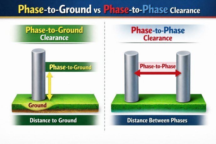
Phase to ground clearance is the minimum safe air distance maintained between an energized conductor and an earthed metal part, enclosure, structure, or the ground itself. Unlike phase to phase clearance, which measures spacing between two live conductors, phase to ground clearance focuses on preventing flashover from a live part to earth.
In most electrical systems, phase to ground clearance is often equal to or greater than phase-to-phase spacing, depending on insulation level, system grounding method, and equipment design.
Phase-to-Ground vs Phase-to-Phase Clearance
| Parameter | Phase-to-Ground Clearance | Phase-to-Phase Clearance |
|---|---|---|
| Definition | Distance between live conductor and earth/metal body | Distance between two live conductors |
| Main Purpose | Prevent earth faults and flashover to grounded parts | Prevent phase faults and arcing between phases |
| Risk Type | Ground fault, insulation breakdown | Short circuit, phase-to-phase arc fault |
| Standard Reference | IEC 61439, IEC 60071, IEC 62271 | IEC 61439, IEC 60071, IEC 62271 |
Why Phase to Ground Clearance Is Important
Proper phase to ground spacing is essential for:
- Preventing accidental grounding faults
- Maintaining insulation coordination
- Reducing electric shock hazards
- Improving equipment safety and reliability
- Managing transient overvoltages and surge conditions
For example, in switchgear and busbar systems, inadequate phase to ground clearance can result in flashover to the panel body, causing equipment damage and safety hazards.
The required phase to ground clearance depends on voltage level, pollution degree, insulation type, and altitude—similar to phase-to-phase design. For complete IEC-based values and application charts, refer to the detailed guide on Phase to Ground Clearance as per IEC 61439.
Importance of Compliance with IEC 61439
Safety and Risk Reduction
Compliant clearance eliminates the risk of phase-to-phase faults due to reduced air gaps. It prevents arcing faults, which can lead to fire, equipment damage, and downtime.
Certification and Testing
Passing dielectric tests is mandatory for assembly certification. Insufficient clearance will cause failure during high-voltage withstand tests. Compliance ensures trouble-free testing and acceptance.
Equipment Longevity
Adequate clearance improves insulation life. Over time, dust and humidity may degrade air insulation. Higher clearances provide an extra safety margin and prolong the service life of electrical panels.
Phase to Phase Clearance in Hazardous Area
Hazardous locations require additional design checks beyond the minimum spacing values specified in IEC 61439. While switchboards and control panels must satisfy insulation clearance requirements, equipment installed in explosive atmospheres must also comply with the relevant IEC 60079 series to prevent ignition risks.
Engineers should verify both electrical insulation distances and explosion protection requirements during equipment selection and installation.
| Consideration | Applicable Standard |
|---|---|
| Panel insulation clearance | IEC 61439 |
| Hazardous area equipment clearance | IEC 60079 Series |
| Explosion protection requirements | IEC 60079-0, IEC 60079-1 |
If your project involves Ex-rated equipment, flameproof enclosures, or Zone 1 and Zone 2 installations, refer to our detailed guide on Phase to Phase Clearance in Hazardous Area. It explains how hazardous area requirements differ from standard LV switchgear clearances and provides practical guidance for IEC 60079 compliance.
Phase to Phase Clearance Calculator
A Phase to Phase Clearance Calculator helps determine the minimum safe spacing required between two energized conductors based on system voltage, insulation level, pollution degree, and installation conditions. Instead of manually checking multiple IEC tables, the calculator provides a quick estimate for design, maintenance, and compliance checks.
This tool is useful for:
- Switchgear and panel design
- Busbar spacing calculations
- Substation layout planning
- Cable termination clearances
- Electrical safety audits
How the Phase to Phase Clearance Calculator Works
The calculator typically uses these input parameters:
| Input Parameter | Description |
|---|---|
| System Voltage | Operating voltage (LV, MV, HV) |
| Impulse Withstand Voltage (Uimp) | Determines insulation coordination level |
| Pollution Degree | Environmental contamination level |
| Altitude | Required for high-altitude correction |
| Insulation Type | Functional, basic, or reinforced |
Based on these values, the calculator estimates the recommended phase spacing according to IEC guidelines and practical engineering standards.
Why Use a Clearance Calculator?
Manual clearance calculations can be time-consuming, especially when dealing with multiple voltage classes or site conditions. A dedicated calculator improves speed, reduces design errors, and helps verify compliance during installation.
Use the Phase to Phase Clearance Calculator below to quickly check the recommended spacing for your application and compare it with IEC standard values.
Phase Spacing for Substations, Busbars & Overhead Lines
Proper phase spacing is essential for maintaining insulation coordination, preventing flashover, and ensuring safe operation of electrical equipment. While Phase to Phase Clearance as per IEC 61439 is primarily applied to low-voltage assemblies, substations and overhead systems require additional consideration of voltage level, insulation, environment, and installation arrangement.
| Application | Main Spacing Consideration |
|---|---|
| LV switchboards | Rated voltage and insulation level |
| Substation busbars | Voltage, impulse withstand and configuration |
| Overhead lines | System voltage, sag and environmental conditions |
For detailed spacing requirements, design engineers should consider applicable IEC, IEEE, and utility standards rather than applying one clearance value to every installation. Our detailed guide on Phase Spacing for Substations explains typical phase-to-phase arrangements for substations, busbars, and overhead conductors, helping engineers select practical spacing during electrical design and layout.
Related Guides
- Phase to Phase Clearance as per NEC / NFPA 70E
- Phase to Phase Clearance for Transmission Voltages (69-500 kV)
Frequently Asked Questions
What is phase to phase clearance?
Phase to phase clearance is the minimum safe air gap between two energized conductors of different phases. It is maintained to prevent arcing, flashover, and short circuits under normal and fault conditions. The required spacing depends on voltage level, insulation type, and environmental factors.
What is the minimum electrical clearance as per IEC 61439?
The minimum electrical clearance as per IEC 61439 depends on the rated impulse withstand voltage (Uimp), pollution degree, and altitude. For example, a 4kV impulse withstand voltage typically requires around 3 mm clearance, while 8kV may require around 8 mm. These values ensure insulation coordination inside low-voltage switchgear assemblies.
What is busbar clearance as per IEC?
Busbar clearance as per IEC refers to the minimum spacing between busbars of different phases and between busbars and earth. Under IEC 61439, typical busbar clearances in 415V systems range from 20 mm to 60 mm depending on current rating, short-circuit level, and panel design.
What is the phase to phase clearance for 415V as per IEC?
For a 415V system, the typical phase to phase clearance as per IEC 61439 is generally between 25 mm and 40 mm in low-voltage panels and switchboards. The exact value depends on the rated impulse voltage, insulation category, and environmental conditions.
How does phase to phase clearance differ from phase to ground clearance?
Phase to phase clearance is the air distance between two live conductors of different phases, while phase to ground clearance is the air distance between a live conductor and an earthed surface or enclosure. Phase-to-phase spacing mainly prevents short circuits, while phase-to-ground spacing prevents earth faults and flashover to grounded parts.
Follow Us on Social:
Subscribe our Newsletter on Electrical Insights for latest updates from Electrical Engineering Hub
#IEC61439, #ElectricalSafetyStandards, #PhaseToPhaseClearance, #PanelBoardDesign, #LowVoltageSwitchgear, #ElectricalCompliance, #SwitchboardStandards, #ClearanceRequirements, #ElectricalEngineeringGuide, #SafetyRegulations
