
Cable Trench Fill Calculator: Accurate and Easy Cable Capacity Tool
Proper cable installation is essential for safety, performance, and future maintenance. One of the most important aspects of underground cable routing is ensuring that a trench has enough space to accommodate all planned cables without overcrowding. This is where a Cable Trench Fill Calculator becomes extremely valuable.
A Cable Trench Fill Calculator helps engineers, electricians, contractors, and project planners determine the available capacity within a cable trench. By calculating the occupied area and comparing it with the total trench space, users can identify whether additional cables can be installed safely while maintaining proper spacing and heat dissipation requirements.
Whether you are working on industrial facilities, power distribution systems, substations, renewable energy projects, or commercial buildings, using a Cable Trench Fill Calculator can improve design accuracy and reduce costly installation errors.
Cable Trench Fill Calculator
Cable Trench Fill Calculator
Accurately compute trench fill volumes, backfill quantities, cable packing ratios, and compliance checks for buried cable installations.
Trench & Installation Parameters
Results
Fill in the parameters and click Calculate to see results.
How to Use This Calculator
Enter the trench length, internal width, and total excavation depth. For sloped or trapezoidal trenches, select the shape and provide the side slope ratio.
Enter the depth of sand/fine gravel bedding below the cables and the surround fill above them. Select the appropriate material for each layer from the dropdown.
Add each cable type with its outer diameter, quantity per layer, and number of layers. The calculator checks packing ratio against the trench width automatically.
Enter the swell factor for excavated material, compaction percentage, and a waste allowance. These adjust the net fill and surplus spoil volumes accurately.
The results panel shows gross excavation volume, layer-by-layer fill breakdown, cable fill ratio compliance, net backfill required, and surplus spoil for disposal.
Technical Reference Notes
Cable Fill Ratio (CFR)
The cable fill ratio compares total cable cross-sectional area to the usable trench cross-section within the cable zone. Recommended maximum is 40% for single-circuit trenches and up to 50% for multi-circuit conduit arrangements. Exceeding this affects heat dissipation and future cable pulling.
Bedding & Surround Specification
BS EN 1610 and IET Wiring Regulations require a minimum 75 mm sand bed below LV cables and 75 mm surround cover above. For HV cables (6.6 kV and above) a minimum 150 mm surround is standard. Lean concrete haunching may be specified in unstable ground or road crossings.
Trapezoidal Trenches
In granular or loose soils, trench walls require a safe slope to prevent collapse. A common side slope is 1:2 (H:V = 0.5) for cohesive soils, and 1:1 (H:V = 1.0) for loose sands. The bottom width still governs cable packing, while volume is calculated from the average of top and bottom widths.
Swell & Compaction Factors
Excavated soil bulks up when disturbed (swell), typically 10–30% for clays and 5–15% for sands. When recompacted as backfill, it may reduce in volume (compaction factor). The net effect determines whether surplus spoil must be carted away or additional imported fill is needed.
Warning Tape & Cover Tiles
Buried warning tape is placed 150–300 mm below finished ground level over LV cable routes, and 300–450 mm over HV routes, per DNO and utility guidelines. Concrete cover tiles provide additional mechanical protection and are placed directly over the surround layer.
Volume Calculation Basis
All volumes are calculated as net in-situ quantities. Rectangular trenches use width x depth x length. Trapezoidal trenches use the prismatoid method with average cross-sectional area. Cable volumes are subtracted from the fill zone to give net void requiring bedding, surround, and backfill materials.
Find more Electrical Engineering Tools for easy electrical calculations and estimations.
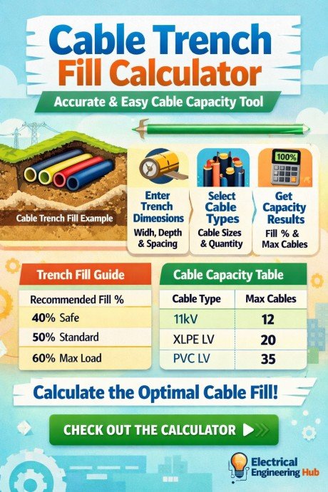
Table of Contents
Table of Contents
Underground Cable Laying: Trench Capacity and Cable Arrangement
Proper Underground Cable Laying requires more than selecting a suitable trench depth. Cable spacing, grouping, heat dissipation, bending radius, and future capacity should also be considered before installation. A properly arranged trench helps prevent excessive cable heating and makes inspection and maintenance easier.
| Trench Consideration | Typical Design Focus |
|---|---|
| Cable spacing | Maintain required separation between circuits |
| Cable depth | Follow project and applicable standards |
| Heat dissipation | Avoid excessive cable grouping |
| Future capacity | Allow space for additional cables |
| Protection | Use sand, tiles, ducts, or covers where required |
Before finalizing the trench arrangement, use a Cable Trench Fill Calculator to estimate available capacity and check whether the proposed cable grouping is practical. For detailed installation methods, spacing, depth, and applicable IEC/IS requirements, see our complete guide to Underground Cable Laying.
What Is a Cable Trench Fill Calculator?
A Cable Trench Fill Calculator is a specialized engineering tool used to calculate the percentage of trench space occupied by cables. It helps determine whether a cable trench meets design standards and has sufficient capacity for current and future cable installations.
The calculator typically considers:
- Trench width
- Trench depth
- Cable diameter
- Number of cables
- Cable arrangement
- Required spacing between cables
Based on these inputs, it calculates the utilized area and available spare capacity within the trench.
Why Cable Trench Fill Calculations Matter
Cable trenches are designed to protect power, control, and communication cables. If too many cables are installed in a limited space, several problems can occur.
Some common issues include:
- Excessive cable heating
- Reduced ampacity
- Difficult maintenance access
- Increased risk of insulation damage
- Non-compliance with engineering standards
- Future expansion limitations
A Cable Trench Fill Calculator helps avoid these issues by ensuring that cable installations remain within acceptable occupancy limits.
Key Parameters Used in Cable Trench Fill Calculations
The accuracy of any Cable Trench Fill Calculator depends on the quality of input data. The following parameters are commonly used.
| Parameter | Description |
|---|---|
| Trench Width | Internal width of the cable trench |
| Trench Depth | Usable depth available for cables |
| Cable Diameter | Outside diameter of each cable |
| Number of Cables | Total cables installed in the trench |
| Cable Spacing | Clearance between adjacent cables |
| Fill Percentage | Portion of trench area occupied by cables |
Engineers should always use actual cable dimensions rather than nominal values for accurate results.
How a Cable Trench Fill Calculator Works
The calculation process is relatively simple. First, the total usable trench area is determined. Next, the combined area occupied by all cables is calculated. Finally, the occupied area is compared with the available trench area to determine the fill percentage.
The basic formula is:
Fill Percentage = (Total Cable Occupied Area ÷ Total Trench Area) × 100
The resulting percentage indicates how much of the trench has been utilized.
Lower percentages generally allow better cooling, easier maintenance, and room for future expansion.
Example Cable Trench Fill Calculation
The following example demonstrates how a Cable Trench Fill Calculator can be used in a real project.
| Input Parameter | Value |
|---|---|
| Trench Width | 800 mm |
| Trench Depth | 600 mm |
| Number of Cables | 12 |
| Cable Diameter | 50 mm |
| Cable Spacing | 25 mm |
| Result | Value |
|---|---|
| Total Trench Area | 480,000 mm² |
| Approximate Cable Area | 23,562 mm² |
| Fill Percentage | 4.9% |
This example shows that the trench still has significant spare capacity for future cable additions.
Cable Trench Design Calculation
A proper Cable Trench Design Calculation helps determine the trench width, depth, cable spacing, and usable capacity before installation. The design should consider cable diameter, number of circuits, heat dissipation, bending radius, and future expansion.
| Design factor | Typical consideration |
|---|---|
| Cable quantity | Count all installed circuits |
| Cable spacing | Follow project/utility requirements |
| Trench depth | Allow cable cover and mechanical protection |
| Width | Cable layout + required clearances |
| Future capacity | Keep spare space for expansion |
For quick capacity checks, the Cable Trench Fill Calculator can estimate how many cables fit within a selected trench size. However, final design should also verify ampacity, thermal effects, separation requirements, and local electrical standards. For a detailed step-by-step approach, see our guide to Cable Trench Design Calculation to plan safer and more practical underground cable installations.
Cable Trench Cable Derating
Cable trench installation can reduce a cable’s heat dissipation when several circuits are grouped together, covered with soil, or installed with limited spacing. Therefore, Cable Trench Cable Derating should be considered after determining the physical cable capacity with a Cable Trench Fill Calculator. Derating factors depend on cable spacing, soil thermal resistivity, ambient temperature, burial depth, and the number of loaded circuits.
| Condition | Possible Effect |
|---|---|
| Multiple loaded cables | Higher heat buildup |
| Closely spaced cables | Reduced heat dissipation |
| Poor soil thermal resistivity | Lower ampacity |
| Greater burial depth | Temperature rise |
For accurate design, apply the applicable correction factors from the relevant IEC, NEC, or manufacturer data rather than relying on a single fixed percentage.
High Voltage Cable Trench Depth Standards
High Voltage Cable Trench Depth Standards help determine the minimum burial depth needed to protect power cables from mechanical damage, temperature effects, and site loads. The required depth varies with voltage level, cable type, installation method, soil conditions, and local electrical codes.
| Installation factor | Typical consideration |
|---|---|
| Medium-voltage cables | Greater depth than typical LV circuits |
| High-voltage cables | Project and utility-specific requirements |
| Road crossings | Additional mechanical protection may be required |
| Cable spacing | Maintain required separation and heat dissipation |
Depth should always be verified against the applicable utility specification, IEC standards, NEC requirements where applicable, and project drawings. After selecting the trench dimensions and cable arrangement, use a Cable Trench Fill Calculator to check whether the proposed trench provides adequate cable capacity and spacing.
For detailed guidance, see our complete guide to High Voltage Cable Trench Depth Standards for practical depth requirements and design considerations.
Here’s a ready-to-publish section designed to fit naturally into your existing calculator article and support internal linking to the spoke topic:
Cable Trench Inspection Checklist
A proper Cable Trench Inspection Checklist helps verify that the trench is safe, correctly constructed, and ready for cable installation or maintenance. After using the Cable Trench Fill Calculator to confirm cable capacity, inspect the physical trench against key installation requirements.
| Inspection Item | What to Check |
|---|---|
| Trench dimensions | Width, depth, and clearances |
| Cable arrangement | Correct spacing and segregation |
| Supports | Secure and properly positioned |
| Water drainage | No standing water or leakage |
| Covers | Secure, accessible, and undamaged |
| Cable protection | No sharp edges or mechanical damage |
Check for debris, excessive moisture, damaged covers, inadequate clearances, and signs of cable overheating. For a detailed field-ready inspection procedure, use this Cable Trench Inspection Checklist as a practical reference.
Benefits of Using a Cable Trench Fill Calculator
A Cable Trench Fill Calculator provides several advantages during design and construction.
Improved Design Accuracy
Manual calculations often lead to errors, especially in large projects involving multiple cable types. Automated calculations improve consistency and accuracy.
Better Thermal Performance
Proper cable spacing allows heat generated by conductors to dissipate effectively, preventing overheating and reducing derating requirements.
Easier Future Expansion
Knowing the available trench capacity helps project teams plan future cable installations without major civil modifications.
Enhanced Safety
Overfilled trenches can increase the risk of cable damage and insulation failure. Proper fill calculations support safe operation.
Compliance With Standards
Many engineering standards recommend maintaining adequate spacing and occupancy limits. A Cable Trench Fill Calculator assists in meeting these requirements.
Factors That Affect Cable Trench Capacity
Several factors influence the actual capacity of a cable trench beyond simple geometric calculations.
Cable Size
Larger cables occupy more space and generate more heat. High-voltage cables typically require greater clearances.
Cable Arrangement
Single-layer cable installations usually provide better cooling than stacked configurations.
Ventilation
Well-ventilated trenches can support higher cable densities compared to enclosed spaces.
Future Spare Capacity
Most engineers reserve additional space for future projects, upgrades, and maintenance requirements.
Thermal Considerations
The surrounding soil conditions, ambient temperature, and cable loading levels can affect allowable trench utilization.
For projects involving medium- and high-voltage systems, understanding trench dimensions is equally important. You can also review our detailed guide on High Voltage Cable Trench Depth Standards to ensure your cable installation complies with recommended depth requirements.
Best Practices When Using a Cable Trench Fill Calculator
To achieve reliable results, follow these best practices:
- Verify actual cable outer diameters from manufacturer datasheets.
- Include spare cables in the calculation.
- Maintain recommended cable spacing.
- Account for future expansion requirements.
- Consider thermal derating factors.
- Follow applicable electrical standards and utility specifications.
- Recalculate capacity whenever cable additions are planned.
These practices help create safer and more efficient cable infrastructure.
Common Applications
A Cable Trench Fill Calculator is widely used across various industries.
| Industry | Application |
|---|---|
| Power Utilities | Underground distribution networks |
| Industrial Plants | Power and control cable routing |
| Solar Farms | DC and AC cable management |
| Wind Farms | Collection system cable trenches |
| Commercial Buildings | Service and feeder cable installations |
| Substations | High-voltage cable trench design |
Because cable trench systems often remain in service for decades, proper capacity planning is critical from the beginning of a project.
Choosing the Right Cable Trench Size
Selecting the correct trench dimensions is one of the most important design decisions. Engineers should consider:
- Current cable requirements
- Future load growth
- Maintenance accessibility
- Heat dissipation requirements
- Applicable design standards
- Project budget
Using a Cable Trench Fill Calculator during the design phase helps optimize trench dimensions while avoiding unnecessary construction costs.
Width Of 400KV Trench
The Width Of 400KV Trench depends on the number of circuits, cable diameter, spacing, heat dissipation, and installation method. For high-voltage cable systems, adequate separation is important to prevent excessive heating and allow safe maintenance access. Before finalizing dimensions, calculate the required cable arrangement and fill space using a Cable Trench Fill Calculator.
| Design Factor | Typical Consideration |
|---|---|
| Cable diameter | Determines spacing and available width |
| Number of circuits | More circuits require a wider trench |
| Cable spacing | Maintain the specified thermal clearance |
| Maintenance access | Provide adequate working space |
| Heat dissipation | Avoid excessive cable grouping |
For detailed dimensions, spacing requirements, and design considerations, see our complete guide to the Width Of 400KV Trench before starting trench construction.
Cable Trench vs Cable Tray: Which Is Better?
Choosing between a cable trench and cable tray depends on installation space, cable quantity, accessibility, and environmental conditions. A trench keeps cables protected below ground, while a tray provides easier access for inspection, maintenance, and future expansion.
| Factor | Cable Trench | Cable Tray |
|---|---|---|
| Installation | Underground | Above ground |
| Protection | High physical protection | Moderate to high |
| Maintenance | More difficult | Easier |
| Expansion | Limited | Easier |
| Space | Requires excavation | Requires support structure |
Before deciding, use a Cable Trench Fill Calculator to estimate cable capacity and avoid overcrowding. For a detailed comparison of installation costs, maintenance, protection, and practical applications, see our guide on cable trench vs cable tray.
Cable Trench vs Duct Bank: Key Differences
When comparing cable trench vs duct bank, the main difference is how underground cables are installed and protected. A cable trench typically places cables directly in a prepared trench with suitable bedding, separation, warning tape, and backfill. A duct bank uses multiple conduits encased in concrete, providing stronger mechanical protection and easier cable replacement.
| Feature | Cable Trench | Duct Bank |
|---|---|---|
| Cable protection | Moderate | High |
| Installation cost | Generally lower | Generally higher |
| Cable replacement | More excavation may be needed | Easier through ducts |
| Best suited for | Utility and industrial runs | Roads, substations, and congested areas |
Before finalizing the trench layout, use a Cable Trench Fill Calculator to check cable capacity, spacing, and available installation space. For a detailed comparison, see our guide on cable trench vs duct bank and choose the arrangement that best matches your project requirements.
Conclusion
A Cable Trench Fill Calculator is an essential engineering tool for determining cable trench capacity accurately and efficiently. It helps designers evaluate trench utilization, maintain proper cable spacing, improve thermal performance, and support future expansion plans.
By using a Cable Trench Fill Calculator early in the design process, engineers can reduce installation risks, improve safety, and ensure compliance with industry requirements. Whether for industrial plants, substations, renewable energy projects, or commercial facilities, accurate trench fill calculations contribute to reliable and long-lasting cable infrastructure.
FAQs
What is a Cable Trench Fill Calculator?
A Cable Trench Fill Calculator is a tool used to determine how much space cables occupy within a cable trench and whether additional capacity is available.
Why is cable trench fill percentage important?
The fill percentage helps prevent overcrowding, improves heat dissipation, and ensures safe cable operation.
Can a Cable Trench Fill Calculator be used for high-voltage cables?
Yes. The calculator can be used for low-, medium-, and high-voltage cables when proper dimensions and spacing requirements are considered.
How much spare capacity should be left in a cable trench?
Many engineers reserve sufficient spare space for future expansion, maintenance access, and thermal performance requirements.
Does cable spacing affect trench fill calculations?
Yes. Cable spacing directly impacts the usable capacity of the trench and plays a major role in thermal management and maintenance accessibility.
What is the required trench depth for electrical cables in India?
For underground electrical cables in India, the typical minimum trench depth is about 750 mm for low-voltage cables and 900–1200 mm for higher-voltage cables, depending on installation conditions and applicable standards.
What is included in the provision of an HT cable trench?
The work includes digging the trench to the specified size, laying HT cables on a river-sand bed, terminating the cables, and covering them with river sand. The trench is then protected with bricks and a red PVC warning tape installed above the cables.
How should a 110 kV cable be laid when crossing a trench?
A 110 kV cable crossing a trench should be laid with adequate mechanical protection, minimum bending radius, and required separation from other utilities. Follow the cable manufacturer’s specifications and applicable IEC/utility requirements for depth, spacing, supports, thermal conditions, and protection.
What is a slanted cable trench?
A slanted cable trench is a cable-routing trench constructed with an inclined or sloping base or sides to improve drainage and manage cable installation. It is commonly used where site conditions require controlled water runoff or changes in elevation.
What does IEC say about substation cable trench earth conductor and power cable separation?
IEC-based substation practice requires adequate separation and safe routing of power cables and earthing conductors to reduce interference and maintain reliable fault-current paths. The exact spacing depends on the installation design, voltage level, fault current, and applicable IEC standard.
How do you check crack width in an underground cable trench?
Crack width is checked by measuring visible cracks with a crack-width gauge and comparing them with the project’s concrete design and applicable standards. Cracks exceeding the specified limit should be assessed for structural safety, water ingress, and durability before repair.
What is the standard depth of trench for underground cable?
For underground electrical cables, a typical trench depth is 600–900 mm (24–36 inches), depending on voltage, installation location, and applicable standards. Higher-voltage or road-crossing installations may require greater depth and additional mechanical protection.
How to know how wide the cable trench required?
The required cable trench width is determined by the number, diameter, spacing, and arrangement of cables, along with required clearances and installation space.
Is a cable trench drain provision necessary?
Yes, a cable trench drain is recommended where water accumulation is possible, especially in outdoor substations and areas exposed to rain or groundwater.
Proper drainage helps prevent cable insulation damage, corrosion, standing water, and unsafe working conditions.
What code applies to communication cable trenches?
Communication cable trenches are commonly designed using TIA-569, NEC Article 800, and applicable local/utility standards. Requirements cover separation, protection, grounding, conduit, depth, and installation practices.
Can a trench cable be routed via a sleeve to an earthing pit?
Yes, a trench cable can be routed through a suitable protective sleeve to an earthing pit, provided the sleeve is properly sized and protected against mechanical damage.
Ensure the earthing conductor remains continuous, has secure connections, and complies with the applicable electrical and earthing standards.
What is the minimum cable trench spacing for a live 132 kV circuit according to Eskom Distribution?
The required separation depends on the specific Eskom standard and cable arrangement; there is no safe universal distance to assume. Always verify the current Eskom Distribution design standard before finalizing trench spacing for a 132 kV live circuit.
Can a 220 kV cable be installed through a trench?
Yes, 220 kV cables can be installed in purpose-designed underground trenches. The trench must meet required clearances, thermal design, cable spacing, earthing, drainage, mechanical protection, and applicable IEC/utility requirements.
What is the recommended side clearance of trefoil cables in a buried trench?
Keep sufficient clearance between the trefoil cable formation and trench walls to allow heat dissipation, installation, and maintenance. A practical minimum is often 100 mm from the trench wall, but the final spacing should be based on cable manufacturer data and applicable IEC/utility requirements.
Can two layers of MV cables be installed in a trench for direct burial?
Yes, two layers of medium-voltage cables can be installed in a direct-buried trench, provided the trench arrangement meets the applicable cable spacing, thermal derating, separation, and ampacity requirements. See more here Cable Trench Cable Derating
What is the installation method factor (k₃) in a cable trench?
The installation method factor (k₃) accounts for how cables are installed in a trench, including spacing, grouping, and surrounding conditions. It is applied to the cable ampacity to account for the effect of the trench installation arrangement on heat dissipation.
If two collection cables in trenches are crossing each other, what cable should be on top and bottom?
Generally, the higher-voltage cable should be placed below and the lower-voltage cable above, maintaining the required separation and mechanical protection. Follow the applicable utility, IEC/NEC, and project specifications for the actual trench arrangement.
What is a cable manhole or trench?
A cable manhole is an underground access chamber for installing, joining, and maintaining cables, while a cable trench is an excavated passage used to route and protect cables.
What is grade in and run in in cable trenching operation?
Grade in and run in refer to the trench’s planned slope (grade) and alignment/route (run). Grade controls drainage and depth, while run defines the horizontal direction and length of the cable trench.
What are cable trench construction methods?
Cable trench construction methods include open-cut excavation, concrete-lined trenches, precast trench systems, and covered or underground duct-bank arrangements. Read more about complete Underground Cable Laying methods here.
Which standard states that a direct-buried cable trench must be clean and free of stones?
IEC 60364-5-52 and common utility specifications require suitable, non-damaging backfill around buried cables; IEC 60502-1 also addresses installation conditions. The requirement for a clean, stone-free trench/bedding is often specified more explicitly in local utility or project specifications to prevent cable sheath damage.
What does IEC say about laying electrical cables in the same trench with water lines?
IEC guidance requires electrical cables and water services in shared trenches to be arranged to prevent mechanical damage, moisture ingress, and unsafe maintenance conditions. Separation, protective measures, burial depth, and local utility requirements must be followed.
The exact clearance is not universally specified by one IEC value; IEC 60364-5-52 and applicable national/utility rules should be checked for the installation. Where practical, provide physical separation and suitable barriers or ducts between electrical and water services.
Why is PEC earthing along cables in trenches installed?
PEC (protective earth conductor) is installed along cables in trenches to provide a low-impedance path for fault current and help protective devices operate quickly during an earth fault.
It also bonds exposed metal parts and helps maintain equipotential bonding, reducing dangerous touch voltages and improving overall electrical safety.
What voltage levels or cable types can share a trench with LV cables, and what separation is required?
The clearance is typically 300 mm (12 inches) between MV and LV cables, unless local electrical codes, utility specifications, or the cable manufacturer require a greater separation.
Is brick protection required over LT cables in a cable trench?
Brick protection is commonly provided over buried LT cables to protect them from mechanical damage and accidental digging. The exact requirement depends on the cable installation method, project specifications, and applicable electrical standards.
How much space is required between MV cables in a cable trench?
MV cable spacing depends on cable voltage, size, installation method, and heat dissipation requirements. Common practice is to maintain about 1 cable diameter between adjacent single-core MV cables, while the final spacing should follow IEC/utility requirements and the cable manufacturer’s ampacity and derating data.
What is the engineering treatment for construction joints in an underground cable trench?
Construction joints should be properly cleaned, roughened, and bonded using an approved bonding agent or cementitious grout before the next concrete pour. Provide waterstops or suitable joint-sealing systems where required to prevent water ingress.
The joint should maintain structural continuity, adequate reinforcement continuity, and a smooth internal trench surface to protect cables and prevent moisture accumulation.
What are the best practices for laying armored cables inside trenches?
Armored cables should be laid on a properly prepared trench bed, maintaining required spacing, bending radius, and depth. Use suitable sand or bedding material, protect cables from sharp objects, and provide warning tape and proper backfilling above the cables.
What are the typical trench sizes for laying electrical cables?
Typical cable trenches are about 450–750 mm wide and 600–1000 mm deep, depending on cable quantity, voltage, soil conditions, and required separation.
The trench should provide adequate cable spacing, protective bedding, warning tape, and cover depth according to the applicable electrical and installation standards.
What is the difference between trenching cable for street lighting and ABC cable mounted to a pole?
Trenching cable is installed underground, providing better protection and a cleaner appearance, while ABC (Aerial Bundled Cable) is mounted overhead on poles for easier installation and maintenance.
Are DC cable backfilling and trench closure the same or different?
They are different but related activities. Backfilling means placing and compacting approved material around and above the DC cables, while trench closure generally refers to completing and restoring the entire trench, including final filling, compaction, surface reinstatement, and finishing.
What are the cable paths running in the ground (trenches) of a big performance hall?
In a large performance hall, underground trenches commonly carry power, lighting, audio/AV, fire alarm, control, data, and other low-voltage cables.
These cables are normally separated, supported, and protected within dedicated routes or compartments to reduce interference and maintain safety.
Can I trench high-voltage DC cables across a campus in the UK?
Yes, HV DC cables can be installed underground across a UK campus, but the design must comply with applicable UK electrical, construction, excavation, fire, and cable-installation requirements.
The route, voltage level, burial depth, separation, protection, earthing, warning systems, and access requirements should be assessed and designed by a suitably qualified engineer.
How far apart should three-phase cables be spaced in a trench?
For a three-phase circuit, keep the three single-core cables close together in a trefoil formation to minimize magnetic effects and voltage drop. For multiple circuits, maintain spacing according to the cable manufacturer’s derating tables and applicable IEC/BS standards.
Which IEC standard should be referred to for GIS substation cable trench routing?
For GIS substations, refer primarily to IEC 61936-1 for power installations above 1 kV, including cable routing, clearances, fire protection, and installation requirements.
For cables, also consider IEC 60502-1/2 and the applicable utility/project specifications for cable installation, segregation, and trench design.
How do you cover cables underground if the coverage is too low?
If underground cable cover is insufficient, increase the depth where practical or provide mechanical protection such as concrete slabs, ducts, cable tiles, or suitable protective conduits.
The required cover and protection should comply with the applicable electrical standard and local utility requirements.
What is the tolerance for a buried cable trench?
The typical construction tolerance for a buried cable trench is about ±50 mm (2 in.) for width and depth, unless project specifications or the applicable standard require tighter limits.
Can you run 6kV cable in the same trench as low-voltage?
Yes, a 6 kV medium-voltage cable can be installed in the same trench as low-voltage cables if the applicable electrical code and utility requirements permit it, with proper physical separation, protection, and cable arrangement.
What is the minimum trench depth required for LV cables (below 1 kV)?
For LV cables below 1 kV, a typical minimum trench depth is 600 mm (24 in) for normal areas, with greater depth often required under roads or vehicle-access areas. Always verify the applicable local utility or installation standard.
What is the standard trench depth for 11 kV / 33 kV MV cables?
For 11 kV and 33 kV MV cables, a typical buried trench depth is around 900–1200 mm, measured from finished ground level to the cable or protective covering. Exact depth should follow the applicable utility specification and installation standard.
How deep should a trench be for HV cables (66 kV–220 kV) as per IEC?
IEC does not specify one universal trench depth for all 66–220 kV cables; the required depth depends on installation conditions, cable system design, and local utility requirements.
As a practical design range, about 1.0–1.5 m cover above the cable is commonly used for HV underground installations, but the project specification should be checked for the exact requirement.
Does the required trench depth change where the route crosses a road or driveway?
Yes. Cable trenches crossing roads, driveways, and other vehicle-access areas generally require greater burial depth or additional mechanical protection compared with normal ground sections.
The exact depth depends on the cable system, installation method, local code, and utility requirements; ducts, concrete encasement, or other protection may also be required.
What is the minimum spacing between HV and LV cables laid in the same trench?
A minimum separation of 300 mm is commonly recommended between HV and LV cables in the same trench to reduce electromagnetic interference and improve safety. However, the exact spacing should follow the applicable IEC standard, utility specification, and cable voltage level.
Can power cables and control/instrument cables share the same trench?
Yes, they can share the same trench if permitted by the applicable electrical standard and project specifications.
However, they should be physically separated, with adequate spacing or barriers to minimize electromagnetic interference and ensure safe installation and maintenance.
What is the safe distance between two parallel MV cables in the same trench?
A typical separation is about 100–300 mm, depending on cable voltage, installation method, thermal loading, and the applicable utility/IEC requirements. For exact design, follow the cable manufacturer’s spacing and the local utility standard.
How thick should the sand bedding be above and below the cable in the trench?
A typical cable trench uses about 75–100 mm (3–4 inches) of clean, screened sand below and above the cable. The exact thickness may vary according to the cable type, voltage level, utility specification, and applicable installation standard.
What backfill material should go above the sand layer in a cable trench?
The backfill above the sand layer should generally be selected, clean, well-graded soil or excavated material free from stones, debris, and sharp objects that could damage the cable or ducts.
At what depth should warning/caution tape be placed in the trench?
Warning or caution tape is typically placed about 300 mm (12 in) above the buried cable or utility, providing a visible warning before excavation reaches the service. Exact depth may vary according to local codes, utility requirements, and the cable installation standard.
How should buried cables be identified or tagged after backfilling?
Buried cables should be identified using durable, weather-resistant marker posts or warning signs above the route, with cable labels showing circuit details and voltage where practical. Record the cable route, depth, and identification in updated as-built drawings for future maintenance and excavation safety.
Do cables in a trench need protective covers, tiles, or slabs?
Yes, underground cables may require protective covers, tiles, or concrete slabs where mechanical protection is needed, such as roads, vehicle-access areas, or shallow installations.
The requirement depends on the cable type, burial depth, installation method, and applicable electrical standard or utility specification.
Is a GI pipe sleeve required where the cable rises out of the trench?
Yes, a GI pipe sleeve is commonly provided where cables rise from a trench to protect them from mechanical damage, impact, and environmental exposure. The sleeve should be properly sized, secured, and finished to prevent sharp edges from damaging the cable.
Does a cable trench need joint bays, manholes, or chambers along its route?
Yes, joint bays, manholes, or cable chambers may be required for long cable routes, cable joints, terminations, bends, or maintenance access. Their spacing and dimensions depend on cable type, voltage level, installation method, jointing requirements, and the applicable standard or utility specification.
What clearance is needed where a cable trench crosses a gas or water pipeline?
A typical minimum vertical clearance is 300 mm (12 in) between the cable installation and a gas or water pipeline, unless local utility rules specify otherwise.
How wide should a cable trench be for single vs. multiple circuits?
For a single cable circuit, a trench is commonly around 300–450 mm wide, while multiple circuits may require 600–1,000 mm or more, depending on cable size, spacing, heat dissipation, and installation method.
Does a cable trench need waterproofing in high-water-table areas?
Yes, cable trenches in high-water-table areas should be properly waterproofed and designed with effective drainage to prevent groundwater ingress, cable insulation damage, and corrosion.
How is trench segregation handled when laying different voltage-level cables together?
Different voltage-level cables should be segregated using separate trench compartments, barriers, or adequate horizontal/vertical spacing to prevent interference, overheating, and fault propagation.
MV/HV cables should generally be separated from LV, control, and communication cables according to the applicable IEC, utility, and local installation requirements.
Does laying cables in multiple layers in one trench reduce their current-carrying capacity?
Yes. Laying cables in multiple layers reduces current-carrying capacity because cables cannot dissipate heat as effectively, requiring derating factors based on cable spacing, number of circuits, installation method, and soil thermal conditions.
For accurate sizing, apply the relevant IEC/BS 7671 or manufacturer derating factors rather than using the single-layer ampacity directly.
Does an earthing conductor need to be laid alongside the power cable in the trench?
Yes. An earthing conductor is commonly laid alongside power cables in the same trench to provide a low-impedance fault-current path and ensure effective bonding of cable armour and equipment. Its size and installation arrangement should comply with the applicable IEC, BS, NEC, or local utility requirements.
Does an earthing conductor need to be laid alongside the power cable in the trench?
Yes, an earthing conductor is commonly laid alongside underground power cables to provide a low-impedance fault-current path and maintain equipotential bonding. The exact arrangement depends on the cable system, installation method, and applicable IEC/BS or local electrical requirements.
Should single-core cables be laid in trefoil or flat formation in the trench?
For single-core AC cables, trefoil formation is generally preferred because it reduces magnetic fields, circulating currents, and induced losses. Flat formation may be used for specific ratings or installation conditions, but spacing and derating must be properly calculated.
When should cables be installed in a duct or pipe instead of a direct-buried trench?
Cables should be installed in ducts or pipes where they need extra protection from mechanical damage, traffic loads, moisture, future excavation, or difficult maintenance conditions.
Ducts are especially useful under roads, pavements, crossings, congested areas, and locations where cables may need to be replaced or additional circuits installed later.
Which IEC or IS standard governs underground cable trench installation?
IEC 61936-1 covers power installations exceeding 1 kV AC and provides requirements relevant to cable installation and underground routing. In India, IS 1255 covers installation and maintenance of power cables up to 33 kV, including laying in trenches.
How is the trench excavated and prepared before laying cable?
The trench is excavated to the specified depth and width, cleared of rocks and debris, and provided with a level sand or approved bedding layer. The cable is then laid with required spacing, separation, and protection before backfilling.
Get new guides in your feed. Follow Electrical Insights on LinkedIn for new electrical standards guides, calculators and design tips from Azad Circuit Hub.
#CableTrenchFillCalculator,#CableTrenchDesign,#CableSizing,#ElectricalEngineering,#CableManagement,#PowerDistribution,#CableInstallation,#ElectricalTools,#EngineeringCalculator,#UtilityEngineering
Cable Trench Fill Calculator: Accurate and Easy Cable Capacity Tool

Use the Cable Trench Fill Calculator to estimate cable occupancy, optimize trench space, and improve electrical installation planning.
Price Currency: USD
Operating System: Web Browser
Application Category: UtilitiesApplication
