Electrical Circuit Calculations & Relays Guide (USA): Formulas & Settings
Electrical circuit calculations help engineers, electricians, maintenance technicians, and consultants select the right components, verify operating limits, and troubleshoot electrical faults. In the United States, these calculations are important when designing control panels, DC power circuits, lighting systems, relay controls, transformers, and industrial equipment.
A reliable Electrical Circuit Calculation starts with the supply voltage, load current, conductor resistance, component ratings, and operating conditions. Engineers must then verify voltage drop, power dissipation, overcurrent protection, and relay contact ratings before approving a design.
This guide focuses on practical electrical calculations used in the USA. It covers common formulas, worked examples, relay selection, voltage drop, resistor sizing, transformer testing, and troubleshooting methods relevant to NEC-based installations and industrial control systems.
Electrical Circuit Calculations: Quick Reference Table
| Calculation | Formula | Typical Application |
|---|---|---|
| Ohm’s law | V = I × R | Voltage, current, and resistance |
| DC power | P = V × I | Power supplies and DC loads |
| Resistance | R = V / I | Circuit analysis |
| Current | I = P / V | Load current estimation |
| Resistor power | P = I² × R | Resistor selection |
| LED resistor | R = (Vs − Vf) / If | Indicator and lighting circuits |
| Voltage drop | Vd = I × R | DC wiring and feeders |
| Single-phase AC power | P = V × I × PF | AC equipment |
| Three-phase AC power | P = √3 × VLL × I × PF | Motors and industrial loads |
| Transformer turns ratio | Vp / Vs = Np / Ns | Transformer analysis |
| Relay coil power | P = V × I | Relay coil sizing |
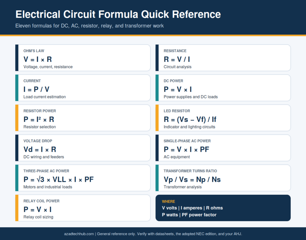
Where V is voltage in volts, I is current in amperes, R is resistance in ohms, P is power in watts, and PF is power factor.
Common Electrical Formulas for US Engineers
A sound Electrical Circuit Calculation begins with the correct electrical model. First, identify whether the circuit is DC, single-phase AC, or three-phase AC. Then determine whether the load is resistive, inductive, capacitive, or electronic.
Ohm’s Law
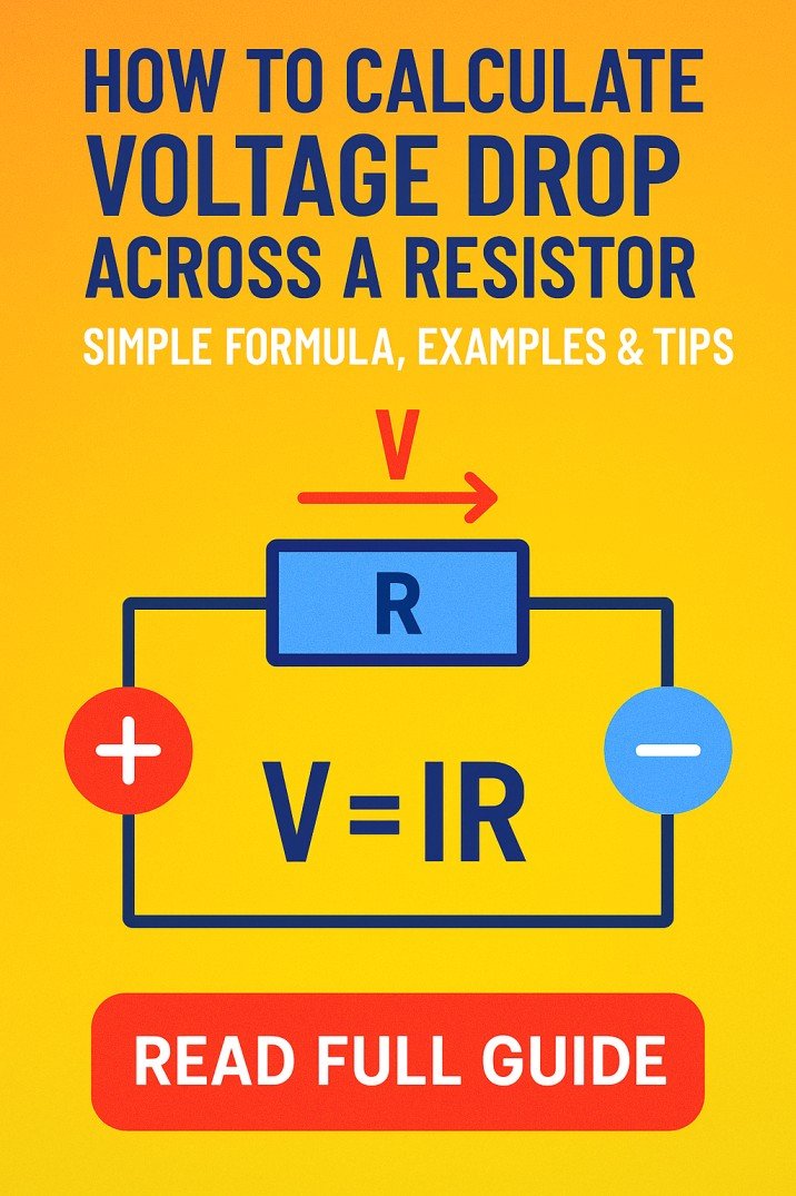
Ohm’s law describes the relationship between voltage, current, and resistance.
Voltage:
V = I × R
Current:
I = V / R
Resistance:
R = V / I
Example: A 24 VDC control circuit has a total resistance of 120 Ω.
I = 24 / 120 = 0.2 A
The circuit current is 200 mA.
This calculation is useful when checking control circuits, relay coils, indicator lamps, and resistive loads. For motors, switching power supplies, and other nonlinear loads, additional parameters may be required.
Electrical Power
For a DC circuit:
P = V × I
For a resistive load:
P = I² × R
P = V² / R
Example: A 12 VDC device draws 2 A.
P = 12 × 2 = 24 W
The power supply must support the device’s steady-state current and any startup current. Engineers should also allow suitable operating margin rather than selecting a supply that runs continuously at its maximum rating.
AC Circuit Power
For single-phase AC:
P = V × I × PF
For balanced three-phase AC:
P = √3 × VLL × I × PF
Where VLL is the line-to-line voltage and PF is the power factor.
For example, a balanced three-phase load operating at 480 V, 10 A, and 0.85 power factor has an approximate real power of:
P = 1.732 × 480 × 10 × 0.85
P ≈ 7,066 W, or 7.07 kW.
This formula assumes balanced three-phase operation and uses line-to-line voltage. Motor efficiency must also be considered when calculating electrical input from a motor’s mechanical output rating.
Step-by-Step Electrical Circuit Calculation Method
Engineers can use the following procedure when checking a new circuit or reviewing an existing design.
- Confirm the supply: Record nominal voltage, frequency, phase configuration, and permitted voltage range.
- Identify the load: Obtain rated current, power, power factor, efficiency, startup current, and duty cycle where applicable.
- Calculate the operating current: Apply the appropriate DC or AC formula.
- Check conductors: Verify ampacity, conductor material, insulation rating, installation method, and voltage drop.
- Select protection: Check fuse or circuit-breaker ratings, conductor protection, and available fault current.
- Verify switching devices: Confirm relay contact ratings for the actual load type and switching duty.
- Check power dissipation: Calculate heat in resistors, contacts, conductors, and power supplies.
- Validate the design: Compare calculated values with equipment documentation and applicable electrical codes.
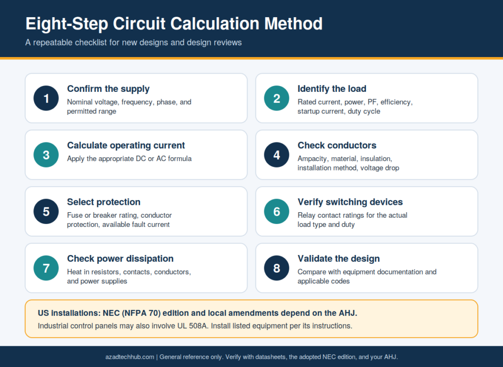
For US installations, the National Electrical Code (NEC), NFPA 70, is a central reference. The adopted edition and local amendments depend on the authority having jurisdiction (AHJ). Industrial control panels may also require consideration of UL 508A, while listed equipment must be installed according to its instructions.
Resistor Sizing for 12V LED Indicators
When adding an LED indicator to a 12 VDC control circuit, the resistor must limit current to a safe operating value. The required resistance depends on supply voltage, LED forward voltage, and target current.
Use:
R = (Vs − Vf) / If
Where:
- Vs = supply voltage in volts
- Vf = LED forward voltage in volts
- If = desired LED current in amperes
Example: A red LED has a forward voltage of 2.0 V and a target current of 10 mA on a 12 V supply.
R = (12 − 2) / 0.01
R = 1,000 Ω
The calculated resistance is 1 kΩ.
Resistor power is:
P = (Vs − Vf) × If
P = (12 − 2) × 0.01 = 0.1 W
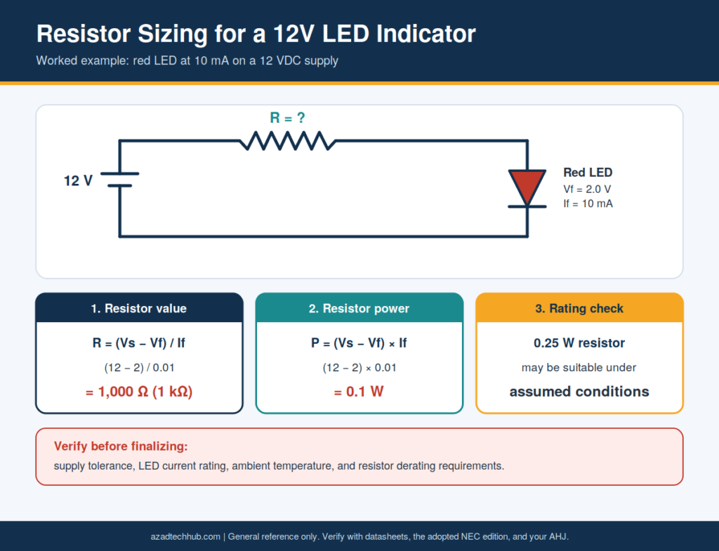
A 0.25 W resistor may be suitable under these assumed conditions, but verify the actual supply tolerance, LED current rating, ambient temperature, and resistor derating requirements.
For practical design work, the dedicated guide on how to calculate the resistor value for a 12V LED circuit can cover resistor selection, standard values, and worked examples.
Reading Five-Band Resistor Markings
Five-band resistors are often used in precision control circuits, instrumentation, and electronic equipment. The first three bands represent significant digits, the fourth indicates the multiplier, and the fifth indicates tolerance.
For example, a resistor marked with red, violet, black, brown, and brown bands represents:
- First digit: 2
- Second digit: 7
- Third digit: 0
- Multiplier: ×10
- Tolerance: ±1%
Resistance = 270 × 10 = 2,700 Ω, or 2.7 kΩ.
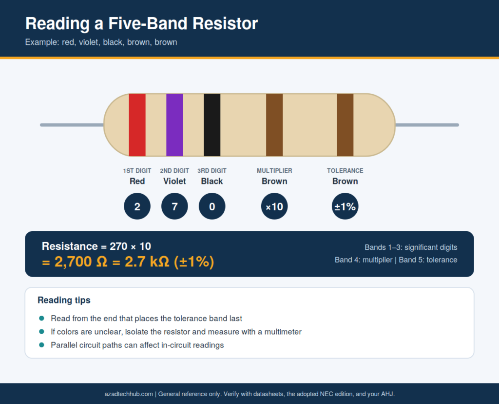
When checking a component, read the bands from the end that places the tolerance band last. If the colors are unclear, isolate the resistor from the circuit and verify its resistance with a multimeter. Parallel circuit paths can affect in-circuit readings.
The related guide on five-band resistor color identification can provide a complete color table, tolerance reference, and additional examples for maintenance technicians.
Selecting a Relay for a 12V, 30A Load
Relay selection requires more than matching the coil voltage and contact current. A 12 VDC relay with a nominal 30 A rating may not be suitable for every 30 A load.
Before selecting a relay, check the following:
| Parameter | What to Verify |
|---|---|
| Coil voltage | Must match the control supply |
| Coil current | Must remain within the control circuit capacity |
| Contact voltage | Must be rated for the actual AC or DC voltage |
| Continuous current | Must support the expected load |
| Load type | Resistive, inductive, motor, or capacitive |
| Inrush current | Must not exceed the permitted switching rating |
| Electrical life | Must suit the switching frequency |
| Terminal rating | Must support the conductor and current |
| Protection | Consider coil suppression and suitable circuit protection |
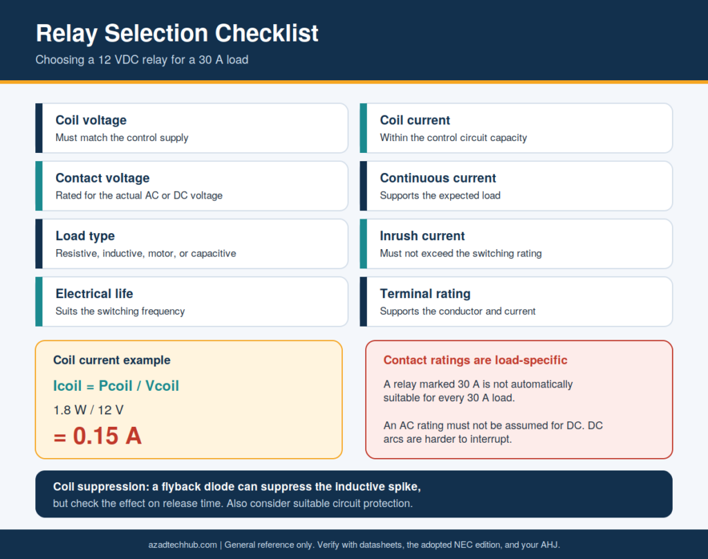
For example, a 12 VDC relay switching a resistive 30 A load at 12 V may require a different contact specification from a relay switching a motor with a high starting current.
Relay contact ratings are load-specific. An AC rating must not be assumed to apply to DC operation. DC arcs can be difficult to interrupt because the current does not naturally cross zero as it does in AC circuits.
The coil current can be estimated from:
Icoil = Pcoil / Vcoil
For a 12 V coil consuming 1.8 W:
Icoil = 1.8 / 12 = 0.15 A
The control circuit must supply at least the required coil current while remaining within the manufacturer’s operating voltage range.
A flyback diode may be used across a DC relay coil to suppress the inductive voltage spike, provided the relay’s release time and circuit behavior remain acceptable. Some applications require a diode-plus-Zener or another suppression method for faster release.
The dedicated article on choosing a 12V relay for a 30A load should address contact ratings, motor inrush, fusing, wiring, and relay socket selection.
DC Voltage Drop in 12V Wiring
Voltage drop is especially important in 12 VDC systems because even a small loss can represent a significant percentage of the supply voltage. It can affect automotive accessories, battery systems, LED lighting, pumps, and remote control equipment.
For a simple DC circuit:
Vd = I × R
For a copper conductor, resistance can be estimated using:
R = ρ × L / A
Where:
- R = conductor resistance in ohms
- ρ = copper resistivity, approximately 0.01724 Ω·mm²/m at 20°C
- L = total conductor length in meters
- A = conductor cross-sectional area in mm²
For a two-wire DC circuit, include both the outgoing and return conductors.
Example: A load draws 10 A through a 5 m one-way copper cable with a cross-sectional area of 4 mm².
Total conductor length = 2 × 5 = 10 m
R = 0.01724 × 10 / 4
R = 0.0431 Ω
Vd = 10 × 0.0431 = 0.431 V
Percentage voltage drop:
Vd% = (0.431 / 12) × 100
Vd% ≈ 3.59%
The load voltage is approximately:
Vload = 12 − 0.431 = 11.569 V
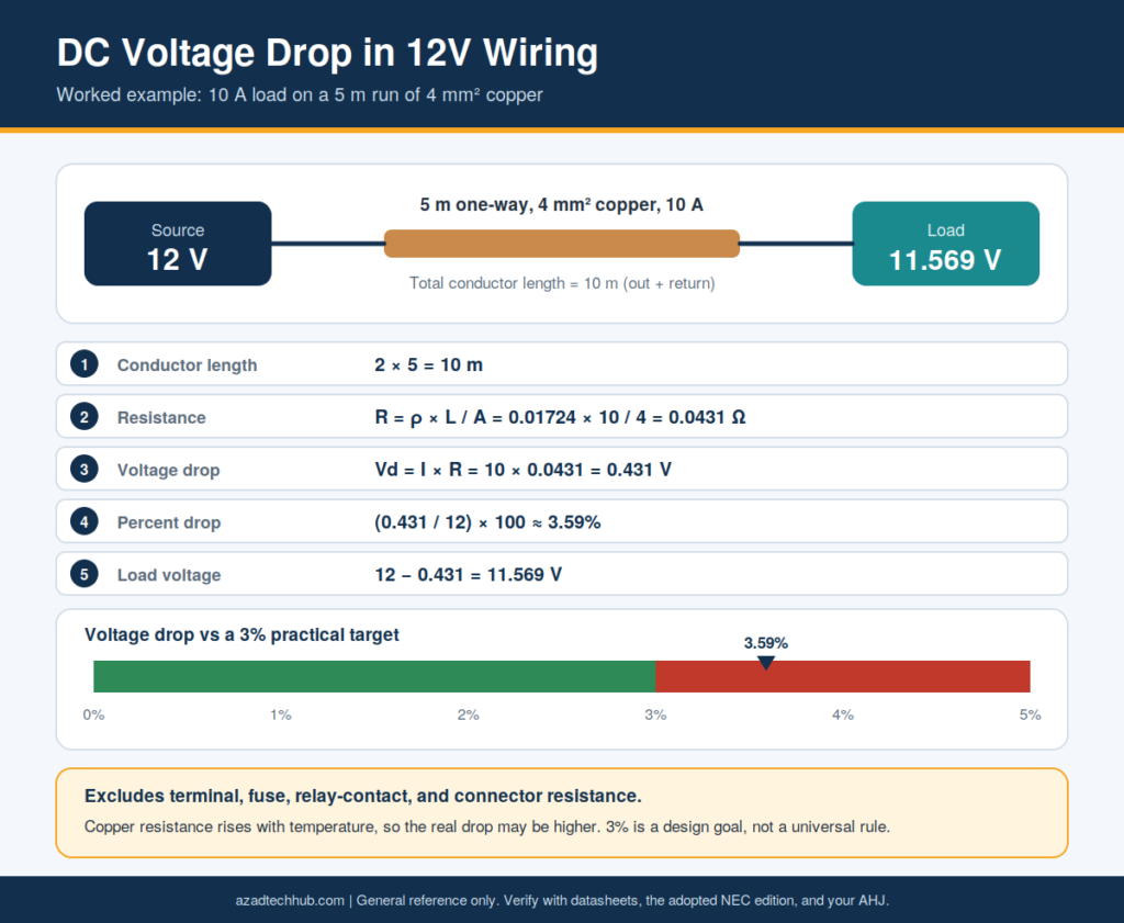
This example excludes terminal, fuse, relay-contact, and connector resistance. Copper resistance also rises with temperature, so the actual voltage drop may be higher.
For final cable selection, check the equipment’s minimum operating voltage, conductor ampacity, insulation rating, installation conditions, and applicable requirements. A voltage-drop calculation alone does not establish that a conductor is safe.
The related guide on voltage drop calculations for 12V DC wire runs can cover wire length, AWG selection, copper resistance, and practical sizing examples.
Transformer Testing With a Digital Multimeter
Transformers are used in control panels, HVAC systems, industrial machinery, and power supplies. A digital multimeter can help identify open windings, incorrect secondary voltage, and certain wiring faults.
Before testing, follow this sequence:
- De-energize the equipment and apply the site’s lockout/tagout procedure.
- Verify absence of voltage with an appropriately rated tester.
- Isolate the transformer winding where necessary to avoid parallel circuit paths.
- Measure primary and secondary winding resistance with the meter’s resistance function.
- Compare readings with the manufacturer’s documentation or a known-good unit.
- Inspect fuses, terminals, insulation, discoloration, and signs of overheating.
- If energized testing is required, restore the circuit only after safe reassembly and perform the test using appropriately rated equipment.
A continuity test can identify an open winding, but low resistance does not prove that a transformer is healthy. A shorted turn may not be detected by a basic multimeter resistance test.
For a transformer with a nominal 120 V primary and 24 V secondary, the ideal voltage ratio is:
Vp / Vs = 120 / 24 = 5
The expected turns ratio is 5:1. Actual measured secondary voltage depends on the supply voltage, load, and transformer regulation.
Never measure resistance on an energized transformer. For live measurements, use suitable CAT-rated equipment, follow safe-work procedures, and observe applicable OSHA and NFPA 70E requirements.
A dedicated guide on testing a transformer with a multimeter can explain winding checks, voltage measurements, continuity tests, and the limits of basic field diagnostics.
Relay Control Circuit Calculations
Relay control circuits often combine a low-voltage control supply with a separate load circuit. The control side operates the coil, while the contact side switches the load.
A basic design review should include:
- Coil voltage and pickup/dropout limits
- Coil current and power consumption
- Contact rating at the actual load voltage
- Motor or solenoid inrush current
- Contact protection and inductive suppression
- Fuse or circuit-breaker coordination
- Control wire ampacity and voltage drop
- Isolation between control and load circuits
For example, a 24 VDC control system may energize a relay that switches a 120 VAC device. The relay must have a suitable coil rating for 24 VDC and a separate contact rating appropriate for 120 VAC and the specific load.
The control and load circuits should be evaluated independently. Their conductors, protective devices, insulation, and enclosure arrangements must meet the requirements for the installation.
For safety-critical applications, consider whether a standard control relay is sufficient or whether a listed safety relay and a validated safety circuit are required.
Short-Circuit Current and Overcurrent Protection
Short-circuit analysis helps determine whether conductors and protective devices can safely withstand a fault. It also helps engineers select equipment with adequate interrupting ratings.
A simplified source calculation is:
Isc = V / Rtotal
Where:
- Isc = prospective short-circuit current
- V = source voltage
- Rtotal = total impedance in the fault path
For example, a 24 VDC source with a total fault-path resistance of 0.12 Ω produces an estimated current of:
Isc = 24 / 0.12 = 200 A
This is a simplified resistive model. Actual fault current may be influenced by battery internal resistance, power-supply current limiting, cable impedance, connections, and the source’s transient response.
For AC systems, engineers normally evaluate source and conductor impedance, transformer impedance, and available fault current at the point of installation. Protective devices must have adequate interrupting ratings for the available fault current, and the design must satisfy the applicable code requirements.
Do not select a fuse solely because its current rating is slightly above the normal load current. Consider conductor protection, inrush, time-current characteristics, fault clearing, and manufacturer instructions.
Practical Troubleshooting of Electrical Circuits
When a circuit fails, use measured values to narrow down the fault rather than replacing components without testing.
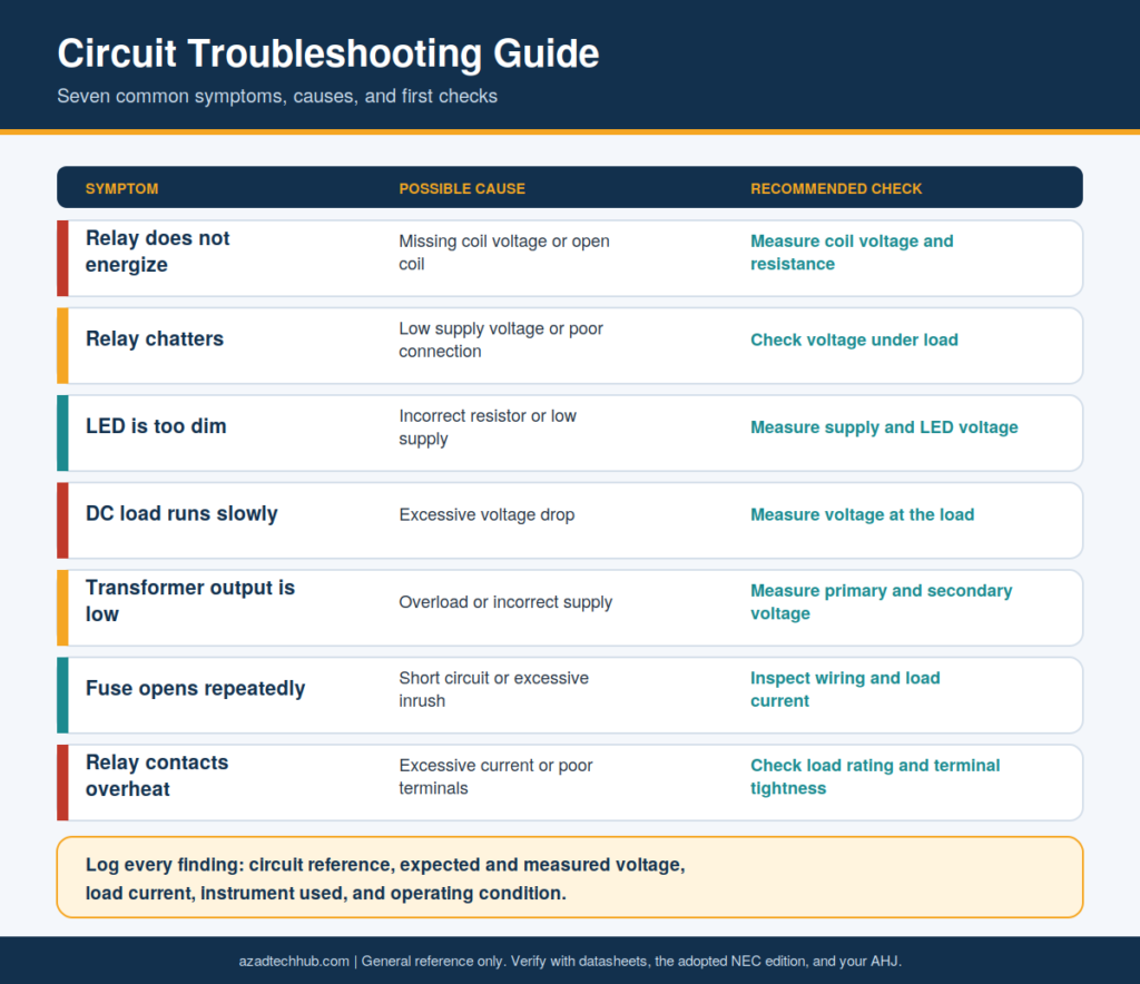
| Symptom | Possible Cause | Recommended Check |
|---|---|---|
| Relay does not energize | Missing coil voltage or open coil | Measure coil voltage and resistance |
| Relay chatters | Low supply voltage or poor connection | Check voltage under load |
| LED is too dim | Incorrect resistor or low supply | Measure supply and LED voltage |
| DC load runs slowly | Excessive voltage drop | Measure voltage at the load |
| Transformer output is low | Overload or incorrect supply | Measure primary and secondary voltage |
| Fuse opens repeatedly | Short circuit or excessive inrush | Inspect wiring and load current |
| Relay contacts overheat | Excessive current or poor terminals | Check load rating and terminal tightness |
A good troubleshooting record should include the circuit reference, expected voltage, measured voltage, load current, instrument used, and operating condition. This makes the findings repeatable and helps distinguish a design issue from a component failure.
US Electrical Standards and Design References
Electrical design and maintenance work in the USA may involve several standards, depending on the installation and equipment.
| Reference | Main Purpose |
|---|---|
| NFPA 70 (NEC) | Electrical installation requirements |
| NFPA 70E | Electrical safety in the workplace |
| UL 508A | Industrial control panel construction |
| UL 489 | Molded-case circuit breakers |
| UL 1077 | Supplementary protectors |
| IEEE guidance | Power-system analysis and engineering practices |
| Manufacturer datasheets | Component ratings and operating limits |
The applicable requirements depend on the equipment, location, adopted code edition, and AHJ. Standards and product listings should be verified for the specific project rather than assumed to apply universally.
Engineers should also document assumptions, calculation methods, protective-device selections, and test results. This creates a clear technical record for design review, commissioning, maintenance, and future modifications.
Frequently Asked Questions
What are the most important electrical circuit formulas?
The most common formulas are V = I × R, P = V × I, R = V / I, and I = P / V. AC systems may also require power factor, phase configuration, and efficiency. The correct formula depends on the circuit and the quantity being calculated.
How do you calculate current in a 12V circuit?
For a DC load with a known power rating, use I = P / V. For example, a 60 W load operating at 12 V draws approximately 5 A under the assumed operating conditions. Check startup current and the actual load voltage before selecting the supply and wiring.
How do you select the correct relay for a 30 amp load?
Confirm the coil voltage, contact rating at the actual AC or DC voltage, load type, inrush current, switching frequency, and electrical life. Verify the terminals, wiring, and protective devices as well. A relay marked 30 A is not automatically suitable for every 30 A load.
How much voltage drop is acceptable in a 12V DC circuit?
The acceptable value depends on the equipment, circuit function, and design requirements. A 3% target is often used as a practical design goal for sensitive low-voltage circuits, but it is not a universal requirement. Check the load’s minimum operating voltage and all applicable standards.
Can a multimeter identify a faulty transformer?
A multimeter can detect an open winding, check continuity, and measure primary or secondary voltage. However, it may not identify shorted turns, insulation breakdown, or every internal fault. More advanced tests may require an insulation resistance tester, turns-ratio tester, or specialized transformer test equipment.
Conclusion
Reliable Electrical Circuit Calculation work requires accurate input data, suitable formulas, and verification against real operating conditions. Engineers should calculate current, power, resistance, voltage drop, and fault current before selecting conductors, relays, fuses, and other components.
In my electrical engineering work, practical circuit checks are most useful when calculations are supported by actual measurements, equipment datasheets, and installation conditions. A relay rating or cable size that appears correct on paper may still fail if inrush current, heat, poor connections, or voltage drop are overlooked.
For US projects, combine sound engineering calculations with the adopted NEC, applicable product standards, safe-work procedures, and manufacturer instructions. This provides a more reliable basis for design, commissioning, and troubleshooting.
Get new guides in your feed. Follow Electrical Insights on LinkedIn for new electrical standards guides, calculators and design tips from Azad Circuit Hub.