Home Electrical Wiring & NEC Code Guide (USA)
Home Electrical Wiring requires careful planning, correct conductor sizing, proper overcurrent protection, and compliance with the National Electrical Code (NEC). In the United States, residential electrical systems commonly use 120V and 240V circuits supplied by a single-phase, three-wire service. The correct design depends on the home’s calculated load, service capacity, wiring method, and local electrical requirements.
This guide covers the technical steps used to plan and evaluate residential electrical systems, from service sizing and branch circuits to grounding, AFCI protection, GFCI protection, and final inspection. It is intended for electrical engineers, consultants, contractors, inspectors, and homeowners who want to understand the engineering behind a safe installation.
In my electrical engineering work, I have seen how small installation errors can lead to overheating, nuisance tripping, equipment damage, and difficult troubleshooting. A sound design starts with calculations and verified code requirements rather than choosing a wire or breaker based on habit.
Home Electrical Wiring: Quick NEC Reference Table
| Electrical Item | Typical Requirement or Reference |
|---|---|
| Standard residential supply | 120/240V, single-phase, three-wire |
| General lighting and receptacle circuits | Commonly 15A or 20A |
| Copper conductors for typical 15A circuits | 14 AWG, subject to code conditions |
| Copper conductors for typical 20A circuits | 12 AWG, subject to code conditions |
| General-purpose 20A branch circuit | Often uses 12 AWG copper |
| Kitchen small-appliance circuits | At least two 20A circuits under applicable NEC rules |
| Bathroom receptacle circuit | At least one 20A circuit for bathroom receptacle outlets |
| Laundry branch circuit | At least one 20A circuit for laundry receptacles |
| Ground-fault protection | Required in specified locations under NEC 210.8 |
| Arc-fault protection | Required for specified dwelling-unit circuits under NEC 210.12 |
| Grounding and bonding | NEC Article 250 |
| Branch circuits | NEC Article 210 |
| Feeders and services | NEC Articles 215 and 230 |
| Residential load calculations | NEC Article 220 |
These are general references, not a complete design specification. Requirements vary with the adopted NEC edition, dwelling type, circuit use, equipment instructions, and local amendments.
1. Understand the NEC Requirements Before Designing the System
The National Electrical Code, published by the National Fire Protection Association as NFPA 70, provides the principal model code for electrical installations in the United States. It becomes enforceable when adopted by a state or local authority, often with amendments.
For residential projects, several NEC articles are particularly important.
| NEC Article | Main Subject |
|---|---|
| 110 | General electrical requirements |
| 200 | Use and identification of grounded conductors |
| 210 | Branch circuits |
| 215 | Feeders |
| 220 | Branch-circuit, feeder, and service load calculations |
| 230 | Services |
| 240 | Overcurrent protection |
| 250 | Grounding and bonding |
| 300 | General wiring methods |
| 310 | Conductors for general wiring |
| 314 | Boxes and fittings |
| 334 | Nonmetallic-sheathed cable |
| 404 | Switches |
| 406 | Receptacles and attachment plugs |
| 408 | Switchboards, switchgear, and panelboards |
Start each project by confirming the adopted code edition with the authority having jurisdiction (AHJ). Also review local permit rules, approved wiring methods, utility service requirements, and manufacturer instructions.
2. Calculate the Residential Electrical Load
A proper electrical design begins with the calculated load. Do not size a service panel by adding the ratings of every breaker. The NEC provides calculation methods that account for dwelling loads, demand factors, fixed appliances, heating, cooling, and other applicable loads.
A typical calculation workflow is:
- Record the dwelling floor area and applicable general lighting load.
- Add the required small-appliance and laundry circuit loads.
- Identify fixed appliances, cooking equipment, dryers, water heaters, and HVAC systems.
- Apply the demand factors allowed by the adopted NEC edition.
- Account for heating and cooling loads using the applicable calculation rules.
- Calculate the resulting service and feeder demand.
- Check the service rating, panel rating, conductor ampacity, and equipment limitations.
For a balanced single-phase load, the basic current relationship is:
I = P / V
Where:
- I = current in amperes (A)
- P = real power in watts (W)
- V = voltage in volts (V)
For example, a 4,800W resistive load operating at 240V draws:
I = 4,800 / 240 = 20A
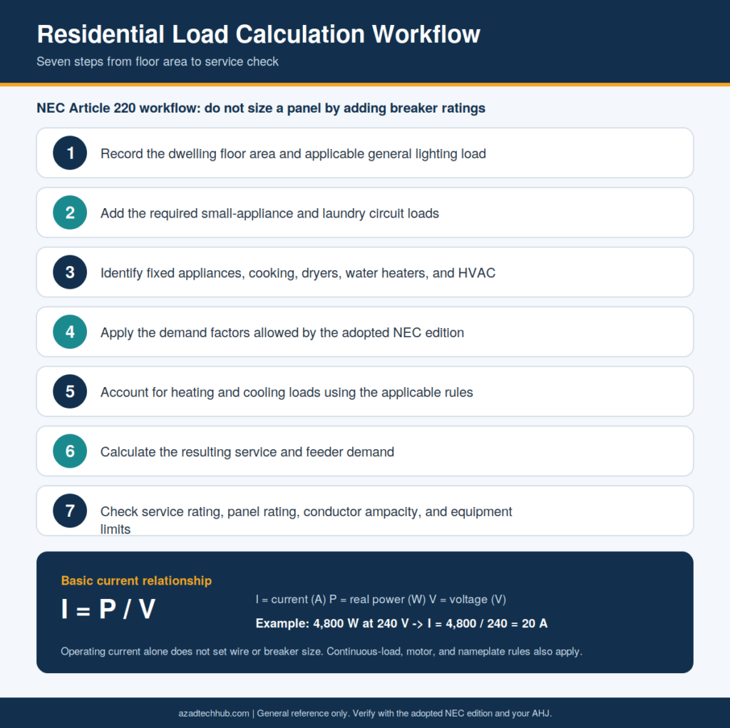
This calculation gives the operating current for the stated load. It does not, by itself, determine the required conductor or breaker size. Continuous-load rules, equipment nameplate ratings, motor requirements, and other NEC provisions may affect the final selection.
3. Select the Correct Wire Size and Circuit Breaker
Conductor sizing is one of the most important parts of Home Electrical Wiring. The selected conductor must safely carry the expected load under the actual installation conditions.
Use this engineering sequence:
- Determine the calculated load and maximum expected current.
- Identify whether the load is continuous, motor-driven, or subject to special rules.
- Select the conductor material and insulation type.
- Determine the applicable ampacity from NEC Article 310 and its tables.
- Apply ambient-temperature and conductor-bundling corrections where required.
- Check the terminal temperature limitations under NEC 110.14(C).
- Verify the overcurrent protection requirements under Article 240.
- Calculate voltage drop when needed and check the installation against equipment requirements.
For ordinary copper branch-circuit conductors, 14 AWG is commonly associated with 15A protection and 12 AWG with 20A protection. These are starting references, not universal rules for every conductor or application.
| Copper Wire Size | Common Branch-Circuit Reference | Important Note |
|---|---|---|
| 14 AWG | 15A | Common residential branch-circuit size |
| 12 AWG | 20A | Common for general 20A circuits |
| 10 AWG | 30A | Common for certain dedicated loads |
| 8 AWG | 40A or 50A applications | Verify ampacity, terminals, and equipment |
| 6 AWG | 50A or 60A applications | Verify insulation and installation conditions |
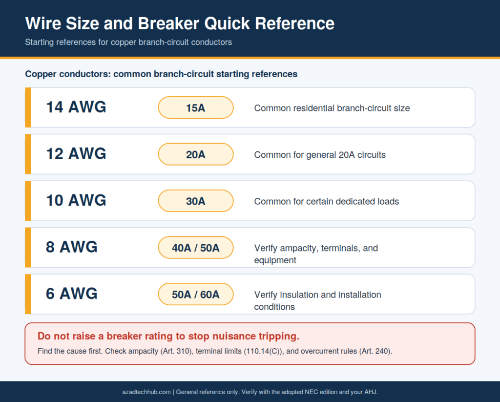
Do not increase a breaker rating to stop nuisance tripping without first identifying the cause. A breaker must protect the installed conductor and comply with the applicable equipment and circuit rules.
For more detailed conductor selection, use the site’s [cable size calculator] and [conduit fill calculator] as supporting references. Verify the results against the applicable NEC tables and project conditions.
4. Plan Branch Circuits and Receptacle Locations
A branch circuit supplies outlets, lighting, or equipment from the final overcurrent protective device. The circuit schedule should identify the breaker number, circuit rating, conductor size, connected equipment, and protected areas.
General-purpose circuits often use 15A or 20A ratings. However, kitchens, bathrooms, laundry areas, garages, outdoor locations, and certain other spaces have additional requirements.
Under applicable NEC provisions:
- Dwelling kitchens require at least two 20A small-appliance branch circuits for specified receptacle outlets.
- Bathroom receptacle outlets require at least one 20A branch circuit.
- Laundry areas require at least one 20A branch circuit for the required laundry receptacle outlet.
- Dedicated circuits may be required by equipment instructions or specific code provisions.
The number of receptacles permitted on a branch circuit is not governed by one universal NEC limit for all dwelling circuits. Check the applicable rules, calculated load, and local requirements before finalizing the layout.
5. Grounding, Bonding, AFCI, and GFCI Protection
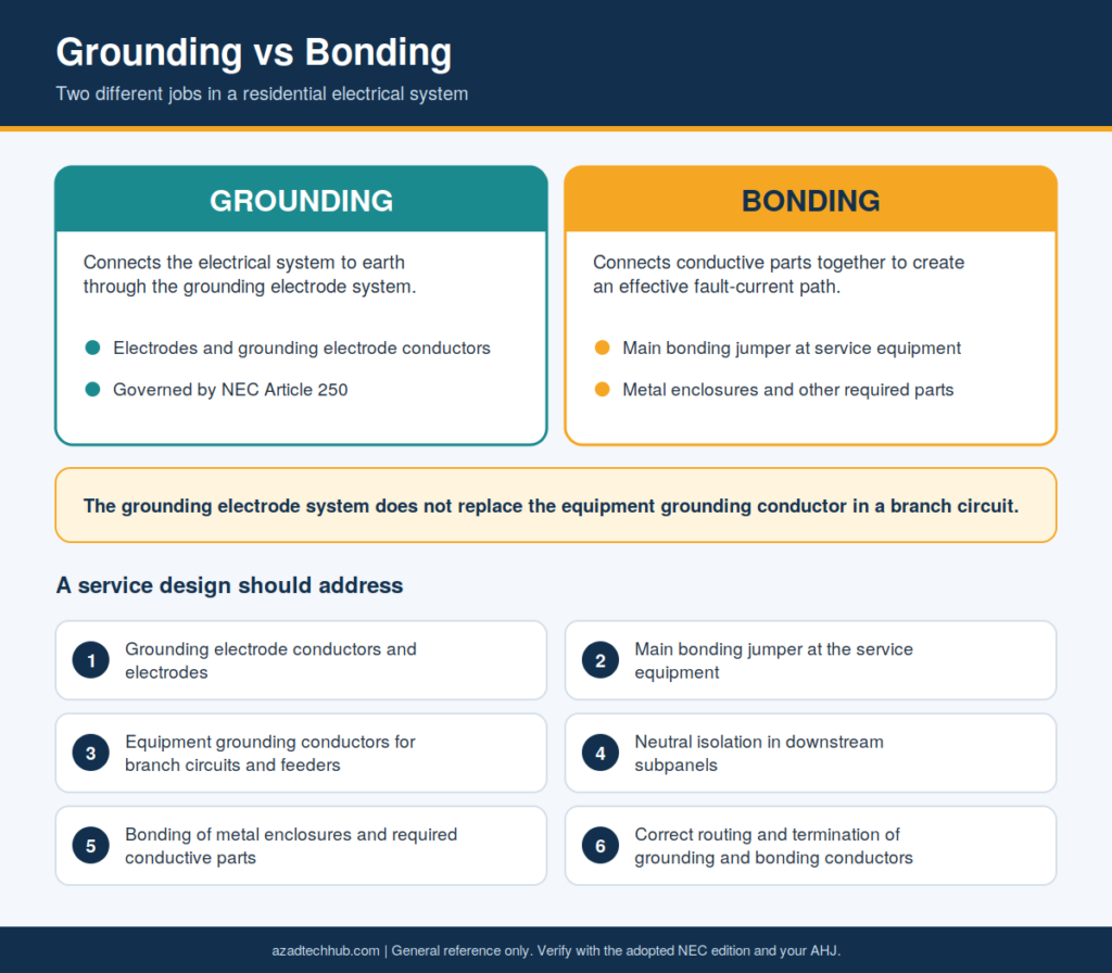
Grounding and bonding serve different purposes. Grounding connects the electrical system to earth through the grounding electrode system. Bonding connects conductive parts to establish an effective fault-current path.
The grounding electrode system does not replace the equipment grounding conductor in a branch circuit.
For a typical service, the design should address:
- Grounding electrode conductors and electrodes.
- The main bonding jumper at the service equipment.
- Equipment grounding conductors for branch circuits and feeders.
- Neutral isolation in downstream subpanels.
- Bonding of metal enclosures and other required conductive parts.
- Correct routing and termination of grounding and bonding conductors.
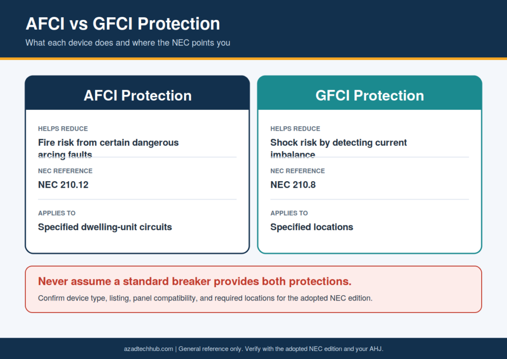
AFCI protection helps reduce fire risks associated with certain dangerous arcing faults. GFCI protection reduces shock risk by detecting current imbalance. NEC 210.12 and 210.8 specify where these protections apply, depending on the adopted edition and installation.
Never assume a standard breaker provides both forms of protection. Confirm the device type, listing, compatibility with the panel, and required locations.
6. Residential Wiring Methods and Installation Checks
Nonmetallic-sheathed cable, commonly called NM-B, is widely used in permitted residential applications. Other wiring methods may be necessary or required for specific locations, exposure conditions, or local rules.
Before installation, check:
- Whether the wiring method is permitted in the location.
- Cable support and securing requirements.
- Protection from physical damage.
- Box fill and conductor fill.
- Connector compatibility and cable entry protection.
- Required separation from heat sources and other services.
- Correct conductor identification.
- Equipment listing and installation instructions.
Under NEC 314.16, box-fill calculations depend on the number and size of conductors, internal clamps, device yokes, and equipment grounding conductors. Under NEC 334.30, NM cable support and securing must meet the applicable requirements.
Do not conceal junctions that must remain accessible. Complete the inspection and testing required for the installation before closing walls.
7. Electrical Load and Circuit Planning for a Home Addition
When adding a room, workshop, finished basement, or large appliance, review both the new branch circuit and the existing service capacity.
A practical assessment includes the connected load, available panel spaces, existing demand calculation, feeder capacity, and the requirements for any new equipment. A spare breaker position does not prove that the service has enough capacity for an additional load.
For larger additions, electric vehicle charging, heat pumps, or workshop equipment, review the applicable load-calculation provisions and manufacturer requirements. A load-management system may be an option where permitted and properly designed.
8. Choosing Between a Main Panel and a Subpanel
A subpanel can help distribute circuits to a garage, workshop, addition, or detached building. Its feeder must be sized for the calculated load and installed according to the applicable feeder, grounding, and bonding rules.
The design should establish:
- Feeder voltage and load.
- Feeder conductor ampacity.
- Overcurrent protection.
- Equipment grounding conductor sizing.
- Raceway or cable suitability.
- Neutral and grounding bar arrangements.
- Disconnecting means and working clearances.
- Additional requirements for detached structures.
In a typical downstream subpanel, the neutral bar is isolated from the enclosure and equipment grounding bar. The service bonding arrangement must remain at the correct location. Detached buildings may have additional grounding and disconnect requirements.
9. Estimating Voltage Drop on Long Branch Circuits
Voltage drop becomes important when a circuit supplies a load over a long conductor run. Excessive drop can affect equipment performance, starting torque, and voltage-sensitive devices.
For a simplified single-phase, two-wire copper circuit, the approximate voltage drop can be estimated as:
VD = 2 × L × I × R
Where:
- VD = voltage drop in volts
- L = one-way conductor length
- I = load current in amperes
- R = conductor resistance per unit length at the relevant operating temperature
Use consistent units. For example, if R is in ohms per foot, L must be in feet.
Percentage voltage drop is:
Voltage Drop (%) = (VD / V) × 100
For a 120V circuit with a calculated 3V drop:
Voltage Drop (%) = (3 / 120) × 100 = 2.5%
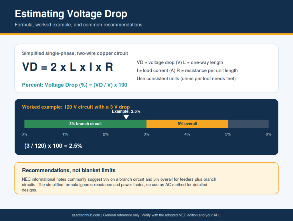
The simplified formula does not account fully for reactance, power factor, or all conductor operating conditions. For detailed designs, use an appropriate AC voltage-drop method and the actual conductor data. NEC informational notes commonly recommend limiting voltage drop to 3% on a branch circuit and 5% overall for feeders and branch circuits, but these recommendations are not blanket mandatory limits for every installation.
10. Inspection, Testing, and Commissioning
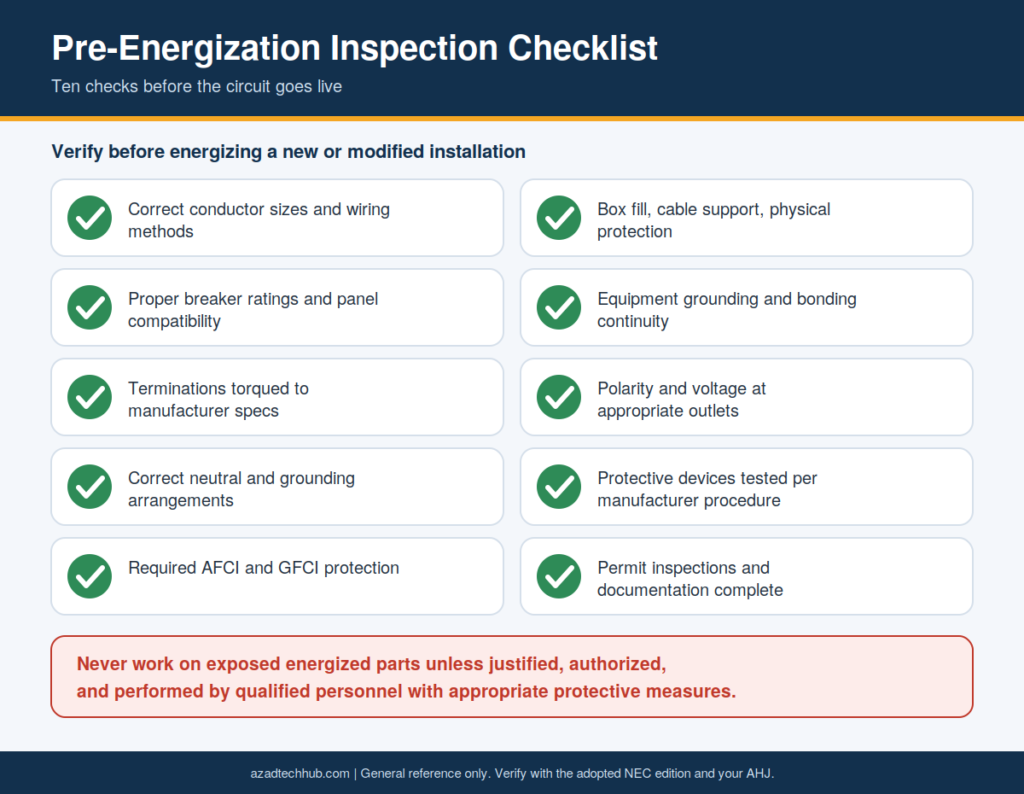
Before energizing a new or modified residential installation, verify that the work matches the approved plans and applicable code requirements.
A qualified professional should confirm:
- Correct conductor sizes and wiring methods.
- Proper breaker ratings and panel compatibility.
- Secure terminations made to manufacturer torque specifications.
- Correct neutral and grounding arrangements.
- Required AFCI and GFCI protection.
- Box fill, cable support, and physical protection.
- Equipment grounding and bonding continuity.
- Polarity and voltage at appropriate outlets.
- Operation of required protective devices using the manufacturer’s approved test procedure.
- Completion of required permit inspections and documentation.
Use suitable instruments and safe test methods. Never work on exposed energized parts unless the task is justified, properly authorized, and performed by qualified personnel using appropriate protective measures.
11. Wire Sizing for a 50A Feeder to a Secondary Panel
A 50A subpanel feeder requires more than selecting a wire from a simple ampacity chart. The engineer must determine the calculated feeder load, conductor material, terminal temperature rating, wiring method, and applicable correction factors. Copper and aluminum conductors may require different sizes.
Check the equipment grounding conductor separately under NEC 250.122, along with feeder overcurrent protection and any applicable neutral requirements. The final design must satisfy the adopted NEC edition and the panel manufacturer’s instructions.
12. Adding Whole-Home Surge Protection at the Main Panel
A whole-house surge protective device can help limit transient overvoltages entering a dwelling through the electrical supply. The installation must use a listed device suitable for the system voltage and panel configuration. Verify the manufacturer’s specified breaker or overcurrent protection, conductor size, lead length, grounding and bonding connections, and installation location.
NEC Article 242 addresses surge-protective devices in applicable installations. Confirm the adopted code edition and panel compatibility before specifying or installing the device.
13. Selecting Overcurrent Protection for a Three-Ton AC Unit
A three-ton air conditioner describes cooling capacity, not the electrical current or breaker rating. The required circuit depends on the unit’s nameplate data, including minimum circuit ampacity (MCA) and maximum overcurrent protection (MOCP), where provided. Follow the equipment instructions and applicable motor and HVAC circuit rules. Do not calculate the breaker size from tonnage alone. The selected conductors must meet the specified ampacity, while the overcurrent device must comply with the equipment’s marked maximum rating and applicable NEC provisions.
14. Controlling Two Lights from Three-Way Switches
A three-way lighting arrangement allows two switches to control the same lights from separate locations. The design uses two three-way switches, traveler conductors, and the correct common-terminal connections. Before wiring, identify the line, switched load, neutral, and grounding conductors from the actual circuit arrangement.
Wire colors alone are not proof of function. The installation must also comply with applicable NEC rules for grounded conductors, switch boxes, grounding, and accessibility. De-energize and verify the circuit before handling conductors.
15. Diagnosing a Circuit Breaker That May Have Failed
A breaker that trips repeatedly may be responding correctly to an overload, short circuit, ground fault, or arc fault. Other causes include loose connections, damaged insulation, moisture, and a defective breaker. Begin by documenting the load and circumstances of each trip.
Check for visible damage, burning smells, heat, or unusual sounds without touching exposed energized components. A qualified electrician can isolate the circuit, perform appropriate tests, and confirm breaker compatibility. Never replace a breaker with a higher-rated device simply to prevent tripping.
16. Locating a Suspected Short Circuit Inside a Wall
A short circuit may result from damaged cable insulation, a failed device, a loose conductor, or a nail or screw penetrating concealed wiring. First, turn off the affected circuit if it can be done safely. Do not open walls or probe conductors while the circuit is energized.
A qualified electrician can isolate loads, inspect accessible boxes, and use suitable diagnostic equipment to narrow the fault location. If wiring damage is suspected, the affected section must be assessed and repaired using an approved wiring method before the circuit is returned to service.
17. Estimating Receptacle Counts on a 20A Branch Circuit
There is no single universal NEC receptacle count for every 20A residential branch circuit. The applicable rules depend on the room, circuit purpose, calculated load, and adopted code edition. Kitchen small-appliance circuits, bathroom receptacle circuits, laundry circuits, and other special-use circuits have specific requirements.
A design should identify the outlets served, expected connected loads, and any equipment that requires a dedicated circuit. Do not use an assumed outlet count as a substitute for load calculations or the relevant NEC provisions.
18. Preparing NM-B Cable Without Damaging the Conductors
When preparing nonmetallic-sheathed cable, avoid cutting, nicking, or removing too much insulation from the individual conductors. Damaged copper can reduce the conductor’s effective cross-section and create a point of overheating or failure. Use a suitable cable-stripping tool and follow its instructions.
Inspect each conductor before termination, and reject or repair damaged wiring using a method permitted by the code. Maintain the required cable sheath inside the box and use approved connectors. Do not leave concealed splices or damaged conductors inside a wall.
19. Evaluating a 100A Versus 200A Service Upgrade
A 200A service can offer greater capacity for electric vehicle charging, electric heating, larger appliances, and future additions, but it is not automatically necessary for every home. Compare the existing calculated load with the anticipated load using the applicable NEC Article 220 method.
The project cost may include utility charges, a new meter socket, service conductors, panelboard, grounding and bonding work, permits, and repairs to finished surfaces. A 100A service may remain suitable for some homes, while others need a larger service or an approved load-management solution. Obtain a site-specific quote before budgeting.
20. Installing a Dedicated 240V Receptacle for Workshop Equipment
A 240V receptacle for a welder must match the equipment’s nameplate requirements, including voltage, input current, duty cycle, plug configuration, and manufacturer instructions. Determine the branch-circuit conductors and overcurrent protection under the applicable NEC rules rather than assuming that every welder requires the same breaker.
Check receptacle rating, grounding, enclosure, cable or raceway suitability, and any required GFCI protection. A qualified electrician should verify the supply and test the completed circuit before the equipment is connected. Never energize an unfinished receptacle or exposed wiring.
21. Identifying the Hot Conductor Safely
A voltage tester can help identify an energized conductor, but the instrument must be suitable for the circuit and used according to its instructions. Non-contact testers can give false readings and should not be the sole basis for declaring conductors safe. A qualified person should use an appropriately rated tester and verify its operation on a known source before and after testing.
Follow a safe isolation procedure, prevent accidental re-energization, and confirm absence of voltage with suitable equipment before touching conductors. Treat unidentified wires as potentially energized until proven otherwise.
Frequently Asked Questions
What size wire is used for standard residential circuits in the USA?
Common examples include 14 AWG copper for many 15A branch circuits and 12 AWG copper for many 20A circuits. Actual conductor selection depends on the load, installation conditions, terminal ratings, and applicable NEC requirements.
Does every home need a 200A electrical service?
No. Service size depends on the calculated load, existing equipment, and anticipated demand. Some homes can operate safely with a smaller service, while homes with extensive electric heating, EV charging, or other large loads may require an upgrade.
Are AFCI and GFCI breakers required in residential installations?
They are required in specified locations and applications under the adopted NEC edition. AFCI protection addresses certain arc-fault hazards, while GFCI protection helps reduce electric shock risk. Confirm the applicable sections and local amendments.
How do I know if my electrical panel is overloaded?
Frequent breaker trips can indicate overloads, but they may also result from faults or defective equipment. Panel capacity cannot be judged by counting breaker handles alone. A load calculation and inspection by a qualified electrician are the appropriate ways to assess available capacity.
Can I install residential wiring without an electrical permit?
Permit and licensing requirements vary by state, county, and municipality. Some jurisdictions allow limited homeowner work, while others require a licensed electrical contractor. Confirm local requirements and inspection procedures before beginning work.
Final Design Checklist for Residential Electrical Projects
A reliable residential installation combines correct calculations, suitable equipment, safe workmanship, and documented compliance. Before approving a design, verify the following:
- The locally adopted NEC edition and amendments.
- Service, feeder, and branch-circuit load calculations.
- Conductor ampacity and overcurrent protection.
- Voltage drop and short-circuit considerations where applicable.
- Grounding, bonding, and neutral isolation.
- Required AFCI and GFCI protection.
- Panelboard compatibility and manufacturer instructions.
- Wiring method, box fill, and physical protection.
- Permit, inspection, testing, and commissioning requirements.
Home Electrical Wiring should always be designed around the actual dwelling, connected loads, and local code requirements. For engineers and consultants, a documented calculation and inspection process provides a stronger basis for safe installations than relying on generic wire-size charts or standard practices alone.
Get new guides in your feed. Follow Electrical Insights on LinkedIn for new electrical standards guides, calculators and design tips from Azad Circuit Hub.