Home Wiring as per CEC / CSA C22.1: Complete Canadian Code Guide
Home Wiring as per CEC is a critical subject for electrical engineers, consultants, contractors, inspectors, and homeowners planning a new installation or renovation in Canada. The Canadian Electrical Code (CEC), published as CSA C22.1, provides the technical framework for safe electrical installations. It covers conductor sizing, overcurrent protection, grounding and bonding, receptacles, branch circuits, service equipment, and many other aspects of residential wiring.
Home Wiring as per CSA C22.1 requires more than following a wiring diagram. The designer must consider the dwelling’s calculated electrical load, conductor ampacity, installation conditions, voltage drop, fault protection, and provincial or territorial requirements. The adopted code edition and local inspection rules also matter because electrical regulations are enforced through the applicable jurisdiction.
This guide focuses on Canadian residential electrical installations. It explains the engineering principles, design checks, code considerations, and common inspection issues that professionals need to understand when assessing or planning home wiring.
Home Wiring as per CEC / CSA C22.1: Quick Reference
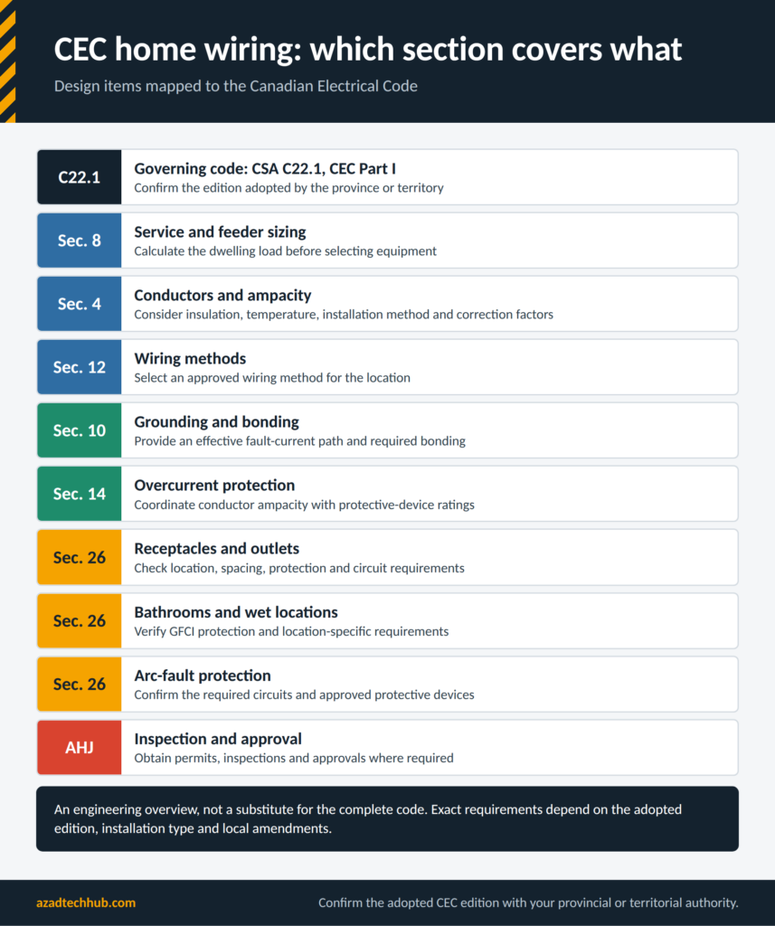
The table is an engineering overview, not a substitute for the complete code. Exact requirements depend on the adopted edition, installation type, and local amendments.
What Is the Canadian Electrical Code CSA C22.1?
The Canadian Electrical Code, Part I, is published by the Canadian Standards Association under the designation CSA C22.1. It establishes safety requirements for electrical installations, including residential wiring, commercial buildings, industrial facilities, and other installations within its scope.
The code is revised periodically to address changes in electrical technology, installation practices, and safety requirements. However, publication of a new edition does not automatically make it the legally applicable edition in every province or territory. The local authority determines when an edition takes effect and whether amendments apply.
For residential projects, engineers should consult the adopted code, relevant provincial regulations, utility service requirements, and the authority having jurisdiction before finalizing the design.
Who Is Responsible for Residential Electrical Compliance?
Responsibilities vary by jurisdiction and project type. A homeowner may be permitted to perform certain work on their own residence in some provinces, subject to conditions and inspection. Other work must be completed by a licensed electrical contractor or qualified electrician.
Electrical engineers and consultants should verify the permitted scope of work rather than assume that a homeowner exemption applies everywhere. Replacing a device, extending a circuit, upgrading a service, and installing a new subpanel may have different permit and qualification requirements.
Canadian Electrical Code vs US Wiring Rules
Canada and the United States both use detailed electrical codes, but their requirements are not interchangeable. Canadian installations are governed by the applicable Canadian Electrical Code and local regulations. US installations generally follow the National Electrical Code (NEC), as adopted and amended by the relevant authority.
| Feature | Canada | United States |
|---|---|---|
| Principal installation standard | CSA C22.1, Canadian Electrical Code, Part I | NFPA 70, National Electrical Code |
| Enforcement | Provincial or territorial authorities | State and local authorities |
| Common residential supply | 120/240 V single-phase | 120/240 V single-phase |
| Typical branch-circuit voltage | 120 V and 240 V | 120 V and 240 V |
| Conductor identification | Follow applicable Canadian requirements | Follow applicable NEC requirements |
| Product acceptance | Certification acceptable to the Canadian jurisdiction | Listing and approval accepted by the US jurisdiction |
| Permits and inspections | Determined by provincial or territorial rules | Determined by state and local rules |
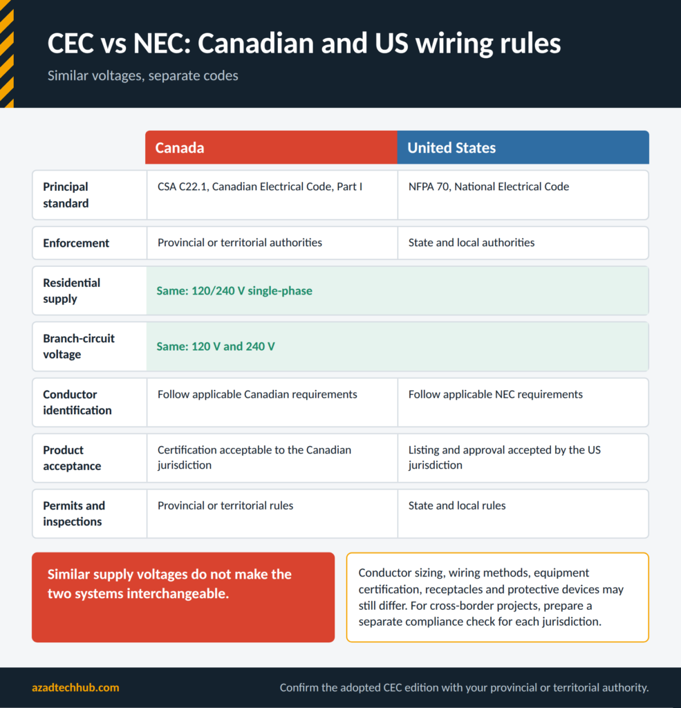
Although supply voltages often look similar, rules for conductor sizing, wiring methods, equipment certification, receptacles, and protective devices may differ.
Planning a Residential Electrical Installation
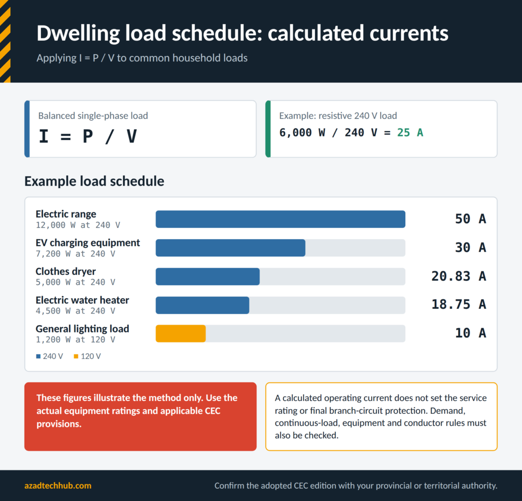
A compliant installation starts with a design, not with pulling cable. The engineer or contractor should identify the dwelling type, supply arrangement, service capacity, expected loads, wiring method, and inspection requirements.
Step 1: Collect the Project Information
Before sizing the electrical service or branch circuits, document:
- Dwelling floor area and number of storeys.
- Existing or proposed service voltage and rating.
- Heating, cooling, and ventilation equipment.
- Electric range, dryer, water heater, and other fixed appliances.
- EV charging equipment, heat pumps, and other large loads.
- Kitchen, bathroom, laundry, and outdoor electrical requirements.
- Planned renovations, additions, and future electrical loads.
- Available utility fault-current information, where required for equipment selection.
The drawings should identify the panel location, circuit routes, outlet locations, major equipment, and any special environmental conditions.
Step 2: Calculate the Dwelling Load
The service rating must be based on the applicable dwelling-load calculation rules rather than simply adding the ratings printed on every breaker. Apply the method prescribed by the adopted CEC edition, including the applicable demand factors and provisions for fixed loads.
A simplified relationship for a balanced single-phase load is:
I = P / V
Where:
- I = current in amperes (A)
- P = real power in watts (W)
- V = supply voltage in volts (V)
For a resistive 240 V load rated at 6,000 W:
I = 6,000 W / 240 V = 25 A
This is the calculated operating current of that load. It does not, by itself, determine the service rating or the final branch-circuit protection. Applicable demand, continuous-load, equipment, and conductor rules must also be checked.
Step 3: Prepare a Load Schedule
Record the connected loads and their supply requirements in a design schedule.
| Load | Supply | Example Rated Power | Calculated Current |
|---|---|---|---|
| Electric water heater | 240 V | 4,500 W | 18.75 A |
| Electric range | 240 V | 12,000 W | 50 A |
| Clothes dryer | 240 V | 5,000 W | 20.83 A |
| General lighting load | 120 V | 1,200 W | 10 A |
| EV charging equipment | 240 V | 7,200 W | 30 A |
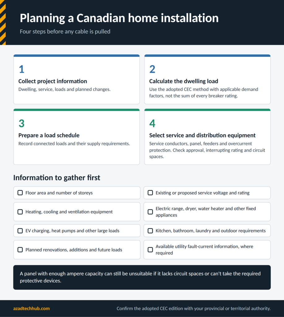
These figures illustrate the calculation method only. Actual equipment ratings, nameplate requirements, demand factors, and applicable CEC provisions must be used for the project.
Step 4: Select the Service and Distribution Equipment
After completing the load calculation, determine the required service conductors, service equipment, panel rating, feeder conductors, and overcurrent protection. Confirm that the equipment is approved for the intended Canadian installation and that its interrupting rating is adequate for the available fault current.
Also verify that the panel provides enough circuit spaces for required branch circuits and reasonable future expansion. A panel with sufficient ampere capacity can still be unsuitable if it lacks spaces or cannot accommodate the required protective devices.
Selecting Conductors and Branch Circuits
Conductor selection is one of the most important technical tasks in Home Wiring as per CSA C22.1. The conductor must safely carry the expected load under the actual installation conditions.
Conductor Sizing and Ampacity
Do not select wire size from current alone. Check the applicable CEC ampacity tables and the relevant requirements for:
- Copper or aluminum conductor material.
- Insulation type and temperature rating.
- Conductor size and terminal temperature limitations.
- Installation method, such as cable, raceway, or other approved wiring system.
- Ambient temperature and conductor grouping.
- Overcurrent protection and applicable load rules.
- Voltage drop and short-circuit withstand requirements where applicable.
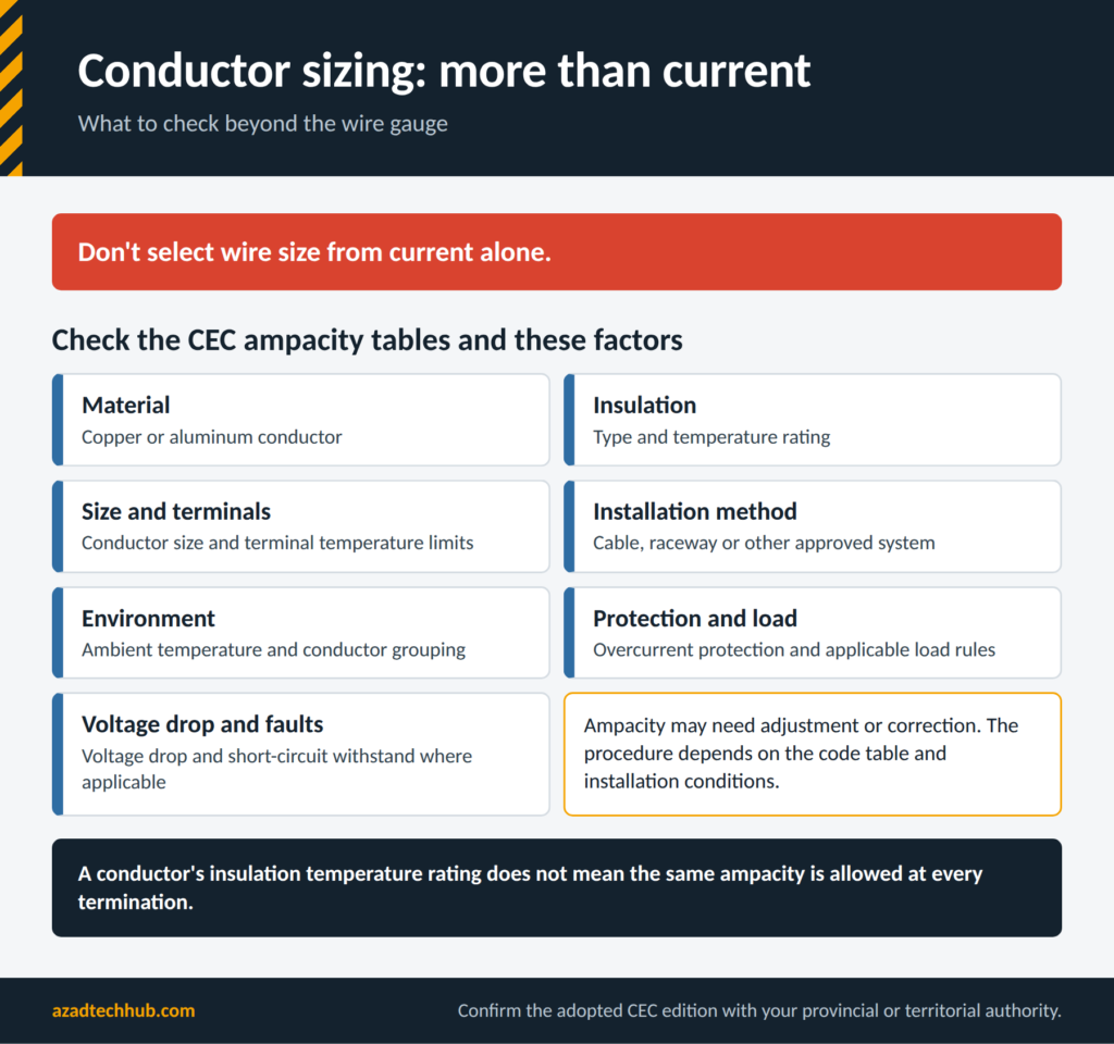
The ampacity available for a conductor may need adjustment or correction. The exact procedure depends on the code table and installation conditions. Do not assume that a conductor’s insulation temperature rating permits the same ampacity at every termination.
Voltage Drop Calculation
Voltage drop is especially important for long branch circuits, detached garages, workshops, and outdoor equipment. Excessive voltage drop can reduce equipment performance and cause problems with motors or other loads.
For a single-phase two-wire circuit, a simplified voltage-drop relationship is:
Vd = 2 × I × L × R
Where:
- Vd = voltage drop in volts
- I = load current in amperes
- L = one-way conductor length
- R = conductor resistance per unit length
The units for L and R must match. If resistance is expressed in ohms per metre, length must be expressed in metres.
The percentage voltage drop is:
Voltage Drop (%) = (Vd / Vs) × 100
Where Vs is the supply voltage.
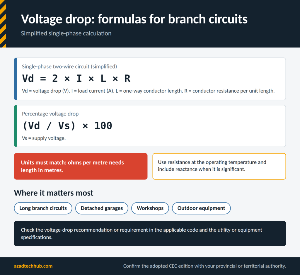
For a practical design, use conductor resistance at the appropriate operating temperature and account for reactance when it is significant. Verify the voltage-drop recommendation or requirement in the applicable code and utility or equipment specifications.
Branch-Circuit Planning
Separate circuits may be required for particular appliances or loads. Kitchen receptacles, laundry equipment, bathrooms, fixed heating equipment, and other loads must be assessed against the relevant CEC provisions.
Prepare a circuit schedule that identifies:
- Circuit number and panel designation.
- Supply voltage and number of poles.
- Conductor size and wiring method.
- Overcurrent device rating and type.
- Load served and calculated demand.
- Required GFCI or AFCI protection.
- Any special disconnecting or equipment requirements.
The schedule should match the electrical drawings and panel directory. Mismatches between the drawings, installed conductors, and panel labels are common causes of confusion during maintenance and inspection.
Grounding and Bonding in Canadian Homes
Grounding and bonding are essential to electrical safety. They help control dangerous touch voltages and provide a path for fault current so the protective device can operate as intended.
Under the applicable CEC requirements, the grounding electrode system, bonding conductors, service equipment, and branch-circuit bonding must be designed as a coordinated system. The neutral-to-bonding connection must be located where permitted by the code; additional neutral-to-ground connections downstream can create parallel current paths.
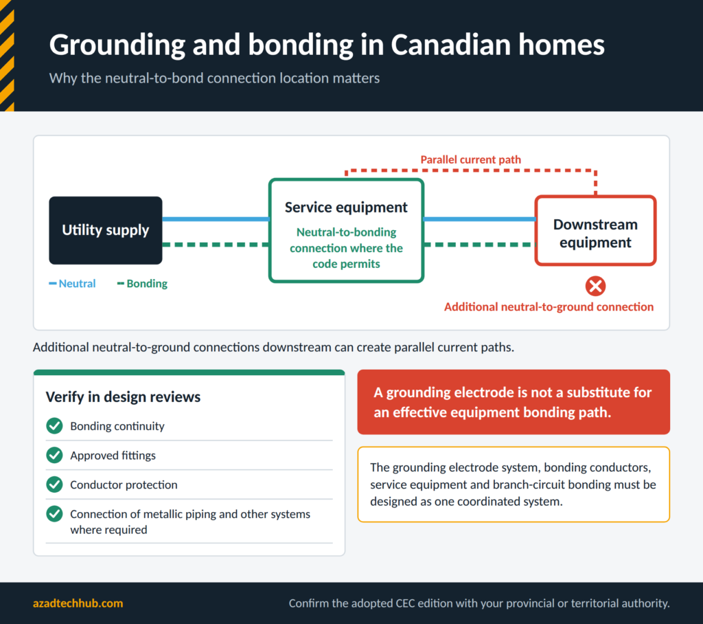
During design reviews, verify bonding continuity, approved fittings, conductor protection, and the connection of metallic piping and other systems where required. Do not treat a grounding electrode as a substitute for an effective equipment bonding path.
Wiring Methods, Cable Routing, and Conduit Fill
Select a wiring method suitable for the building construction, environment, and mechanical exposure. Canadian residential installations commonly use approved non-metallic-sheathed cable in permitted locations, while raceways and other wiring methods may be appropriate for exposed runs, garages, unfinished spaces, and specialized installations.
The applicable CEC requirements determine where each wiring method can be used and how it must be supported, protected, and terminated.
For raceway installations, calculate conductor fill using the applicable rules and tables. The external cable diameter, insulation type, number of conductors, and raceway dimensions can affect the result. Use a dedicated conduit fill calculator as a preliminary check, then verify the calculation against the adopted code.
Panelboards, Breakers, and Circuit Identification
The panelboard is the main distribution point for most residential branch circuits. Its rating, bus configuration, approved breaker types, interrupting capacity, and available spaces must suit the installation.
Engineers should check the calculated service load, feeder capacity, breaker compatibility, and the manufacturer’s panel instructions. Do not install a breaker simply because it fits physically. The device must be approved for that panel and suitable for the intended circuit.
Every circuit should have a clear, accurate directory. Labels such as “lights” or “plugs” may be insufficient when multiple areas share similar loads. A useful directory identifies the rooms, appliances, and equipment supplied by each circuit.
Receptacle Placement and Protection Requirements
Receptacle planning should begin with room use, furniture layouts, fixed appliances, and the requirements of the adopted CEC edition. Kitchen counters, bathrooms, laundry areas, garages, outdoors, and other special locations may have specific rules for receptacle placement and protection.
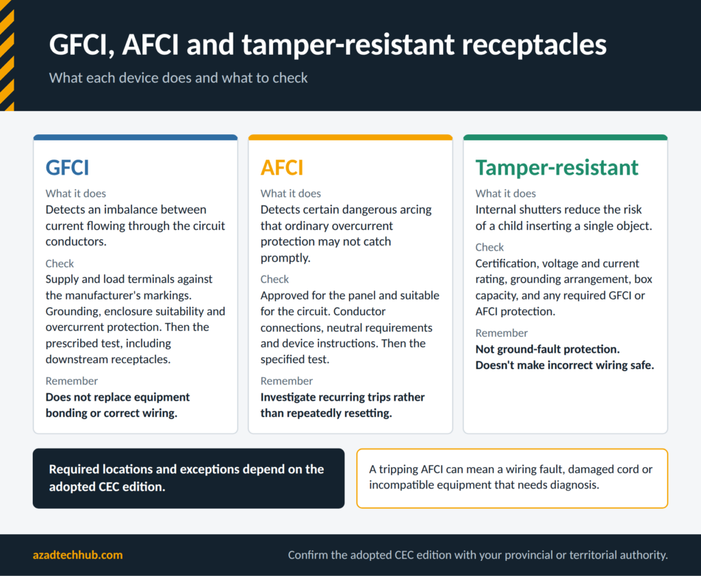
Confirm the required receptacle type, grounding, circuit arrangement, and GFCI or AFCI protection. Receptacles exposed to moisture or weather also need suitable equipment and enclosures for the location.
For renovations, inspect the existing circuit before adding receptacles. Its conductor size, protection, loading, and wiring method must be suitable for the proposed extension. An available terminal or nearby outlet does not automatically mean the circuit has sufficient capacity.
Inspection, Testing, and Commissioning
Before an installation is energized, verify that the completed work matches the approved drawings and applicable code. Testing should be performed by qualified personnel using suitable instruments and safe procedures.
A practical inspection and testing plan includes:
- Visual inspection of conductors, terminations, enclosures, and cable support.
- Verification of conductor identification and bonding connections.
- Confirmation of overcurrent device ratings and compatibility.
- Continuity testing of protective bonding paths where appropriate.
- Insulation resistance testing where required and suitable for the equipment.
- Verification of polarity and supply voltage.
- Functional testing of GFCI, AFCI, and other protective devices according to their instructions.
- Documentation of deficiencies, corrections, and required inspection approvals.
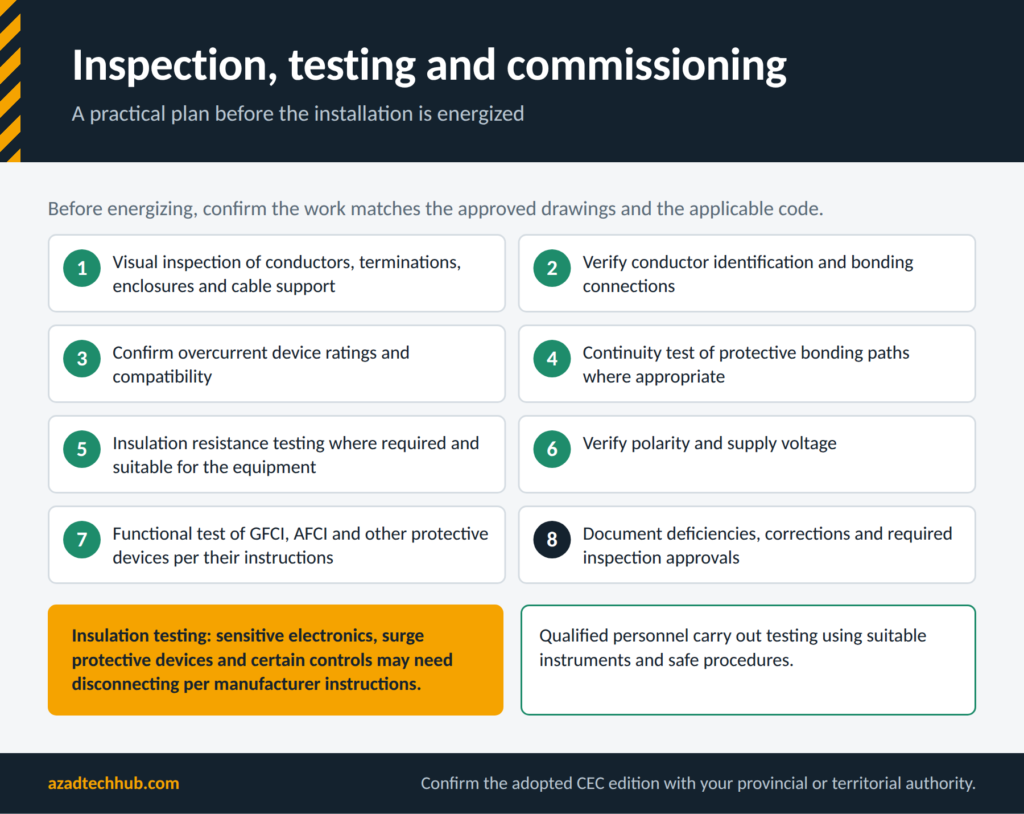
Testing methods must suit the connected equipment. Sensitive electronics, surge protective devices, and certain controls may need to be disconnected or handled according to manufacturer instructions before insulation testing.
Differences Between Canadian and American Residential Wiring Standards
Canadian residential electrical work follows the CEC as adopted by the relevant province or territory, while US installations follow the NEC as adopted by their local authority. Both systems address electrical shock, fire risk, conductor ampacity, overcurrent protection, and grounding, but their detailed rules can differ.
Engineers comparing drawings should review conductor sizing, approved wiring methods, device certification, receptacle requirements, and protective-device rules. Similar supply voltages do not make the systems interchangeable. For cross-border projects, prepare separate compliance checks for each jurisdiction rather than transferring a US design directly into a Canadian home.
Rules for Replacing a Switch in an Ontario Home
Replacing a light switch may appear simple, but the legal requirements depend on Ontario’s electrical safety rules and the nature of the work. Before starting, confirm whether the work can legally be performed by the homeowner or requires a Licensed Electrical Contractor. Permit and notification requirements must also be checked with the Electrical Safety Authority (ESA).
From a technical perspective, the circuit must be de-energized and verified dead using an appropriate tester. The replacement device must match the circuit rating, conductor arrangement, box conditions, and intended switching function. If the wiring is unfamiliar or damaged, stop and obtain qualified assistance.
Important Updates in the 2024 Canadian Electrical Code
The 2024 edition of CSA C22.1 introduced revisions to the Canadian Electrical Code, but the applicable requirements depend on the edition adopted by the province or territory and its effective date. Homeowners and consultants should not assume that every change in the published edition is already enforceable at a particular location.
Before preparing drawings or inspecting an installation, check the jurisdiction’s current adoption notice and amendments. Review changes that affect residential circuits, protective devices, equipment installation, conductor requirements, and renewable-energy or EV charging systems where applicable. Use the actual code text for compliance decisions rather than relying solely on summaries of code changes.
Ground-Fault Protection for Canadian Receptacles
Ground-fault circuit interrupters (GFCIs) help protect people by detecting an imbalance between current flowing through the circuit conductors. The required locations and installation conditions must be checked against the adopted CEC edition.
For a GFCI receptacle, verify the supply and load terminals against the manufacturer’s markings. Incorrect connections can prevent downstream protection from working as intended. Confirm grounding requirements, enclosure suitability, and the circuit’s overcurrent protection. After installation, perform the manufacturer’s prescribed test and verify the operation of any downstream receptacles. GFCI protection does not replace equipment bonding or correct wiring.
Choosing Conductors for a 60 A Subpanel
A 60 A subpanel feeder must be designed around the calculated load, conductor ampacity, terminal ratings, installation method, voltage drop, and applicable CEC rules. There is no single conductor size that is correct for every installation.
Copper and aluminum conductors may have different permitted sizes for the same application. Ambient temperature, cable grouping, insulation type, and termination temperature ratings can also affect the final selection. The feeder’s overcurrent protection, panel rating, and bonding arrangement must be coordinated. Where the subpanel is in a separate building, additional requirements for the feeder, bonding, grounding electrodes, and disconnecting means may apply.
Comparing 100 A and 200 A Service Upgrades
A 100 A service may be sufficient for some homes, while a 200 A service can provide more capacity for electric heating, an EV charger, a larger range, or future additions. The correct choice comes from the required load calculation and the available utility supply, not simply from the home’s age or floor area.
A service upgrade can involve the panel, service conductors, meter equipment, grounding and bonding, utility coordination, permits, and inspections. Costs vary by province, access, equipment, and the extent of the work. Before specifying an upgrade, determine whether load management or another compliant design could meet the demand.
Arc-Fault Protection in Residential Branch Circuits
Arc-fault circuit interrupters (AFCIs) are designed to detect certain dangerous electrical arcing conditions that ordinary overcurrent protection may not detect promptly. The CEC specifies where AFCI protection is required, subject to the adopted edition and applicable exceptions.
When selecting an AFCI breaker, confirm that it is approved for the panel and suitable for the circuit. Check conductor connections, neutral requirements, device instructions, and compatibility with the circuit arrangement. After installation, perform the specified test and investigate any recurring trips rather than repeatedly resetting the breaker. A tripping AFCI can indicate a wiring fault, damaged cord, incompatible equipment, or another condition requiring diagnosis.
Recognizing Aluminum Conductors in Older Canadian Houses
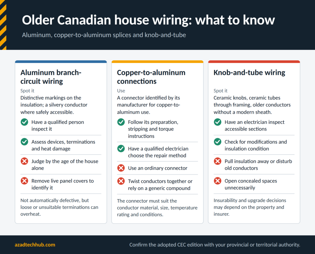
Some older Canadian homes contain aluminum branch-circuit conductors. Their presence should be established through a careful inspection by a qualified person, not by the age of the house alone. Aluminum conductors may have distinctive markings on the insulation, and the conductor itself can appear silvery when safely accessible.
Do not remove live panel covers or expose wiring simply to identify the material. Aluminum wiring is not automatically defective, but connections must be suitable for the conductor type and installation. Loose, damaged, or unsuitable terminations can overheat. A qualified electrician should assess the wiring, devices, terminations, and any signs of heat damage before recommending repairs.
Safe Connections Between Copper and Aluminum Conductors
Copper and aluminum conductors must not be joined using an ordinary connector unless it is specifically approved for that combination and the intended application. A proper connection must accommodate the conductor material, size, temperature rating, and installation conditions.
Use a connector identified by its manufacturer for copper-to-aluminum use, and follow its preparation, stripping, torque, and installation instructions. Do not rely on twisting conductors together or applying a generic compound as a substitute for an approved connection. Existing aluminum branch-circuit wiring should be assessed by a qualified electrician, who can determine the appropriate repair method under the applicable Canadian requirements.
Checking for Legacy Knob-and-Tube Wiring
Knob-and-tube wiring may be found in older Canadian houses. Visible indicators can include ceramic knobs supporting conductors, ceramic tubes passing through framing, and older conductors without a modern cable sheath. These clues are useful for identifying areas that need professional assessment, but they do not establish the full condition of the installation.
Do not pull insulation away, disturb old conductors, or open concealed spaces unnecessarily. Some older wiring may have been altered or extended over time. A qualified electrician should inspect accessible sections, identify modifications, assess insulation condition, and determine whether the installation remains suitable for its use. Insurability and upgrade decisions may also depend on the property and insurer.
Wiring a Two-Location Lighting Circuit
A three-way switching arrangement allows one light to be controlled from two locations. In Canadian residential wiring, the circuit design depends on the source, light location, switch positions, and cable route. The number of conductors required between boxes must be determined from the actual arrangement, not assumed from a generic diagram.
A 14/2 cable contains two insulated conductors and a bonding conductor; a 14/3 cable contains three insulated conductors and a bonding conductor. These descriptions alone do not establish suitability. Conductor size, circuit protection, cable type, and permitted wiring method must be verified. Identify the common and traveller terminals from the device markings and the approved circuit diagram.
Tamper-Resistant Receptacles for Canadian Homes
Tamper-resistant receptacles use internal shutters designed to reduce the risk of a child inserting a single object into a receptacle opening. Whether they are required at a particular location depends on the applicable CEC edition and jurisdictional requirements.
When specifying replacements or new installations, verify the device certification, voltage and current rating, grounding arrangement, box capacity, and required GFCI or AFCI protection. The receptacle must be suitable for the environment and installed according to the manufacturer’s instructions. Do not assume that a tamper-resistant device provides ground-fault protection or makes an incorrectly wired circuit safe.
Signs That a Residential Panel May Be Overloaded
A panel should be assessed using a proper load calculation and inspection, not just the number of installed breakers. Warning signs can include recurring breaker trips, overheating, burning smells, buzzing, discoloured components, or evidence of damaged insulation. These symptoms require prompt investigation.
The presence of unused breaker spaces does not prove that the service has spare electrical capacity. Conversely, a panel with many breakers is not necessarily overloaded. An engineer or qualified electrician should review the calculated load, conductor and feeder ratings, breaker compatibility, equipment condition, and any large loads being added. If there is smoke, active arcing, or a burning smell, keep away and seek emergency assistance as appropriate.
Final Design Checklist for Canadian Residential Wiring
Before submitting a residential electrical design or requesting final inspection, use the following checklist to identify common omissions.
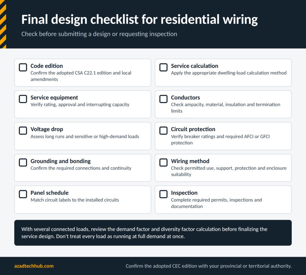
For projects with several connected loads, review the demand factor and diversity factor calculation before finalizing the service design. These concepts help engineers determine the design load using the applicable code method rather than treating every connected load as though it operates at full demand simultaneously.
Frequently Asked Questions
1. What is the Canadian Electrical Code for home wiring?
The Canadian Electrical Code, Part I, is published as CSA C22.1. It provides safety requirements for residential and other electrical installations. The legally applicable edition, amendments, permits, and inspection procedures are determined by the relevant provincial or territorial jurisdiction.
2. Can a homeowner do their own electrical wiring in Canada?
The answer depends on the province or territory, the type of property, and the work involved. Some jurisdictions permit homeowners to perform certain electrical work on their own residences under specific conditions. Others require a licensed electrical contractor or impose additional restrictions. Always confirm the local rules and inspection requirements before beginning work.
3. What wire size is required for a 60 amp subpanel in Canada?
There is no single conductor size suitable for every 60 A subpanel. The required size depends on conductor material, insulation, installation method, terminal ratings, temperature corrections, voltage drop, and the applicable CEC rules. The feeder and overcurrent protection must be designed together, and the calculated load must not exceed the permitted capacity.
4. Are GFCI and AFCI breakers required in Canadian homes?
GFCI and AFCI protection are required for specified applications and locations under the applicable Canadian Electrical Code edition. Their precise requirements and any exceptions must be verified for the jurisdiction and installation. A qualified electrician should select compatible devices, install them according to their instructions, and test their operation.
5. How much does it cost to upgrade a home electrical panel in Canada?
The cost depends on the existing service, proposed rating, location, utility requirements, panel and meter equipment, wiring modifications, permits, and inspection work. A straightforward panel replacement may cost much less than a complete service upgrade involving new service conductors or extensive alterations. Obtain local quotations after a load assessment and site inspection rather than relying on a national average.
Conclusion
Home Wiring as per CEC requires careful planning, sound electrical calculations, approved equipment, and compliance with the rules adopted by the local authority. Engineers and consultants must consider service capacity, conductor ampacity, voltage drop, overcurrent protection, grounding and bonding, wiring methods, and the requirements for receptacles and protective devices.
In my electrical engineering work, I have found that a well-designed installation starts with the actual load and installation conditions, not with a standard wire-size assumption. The same principle applies when assessing an older home, planning an EV charger, or upgrading a distribution panel.
For a reliable result, consult the applicable CSA C22.1 edition, verify provincial or territorial requirements, coordinate with the utility where necessary, and arrange the required inspection before the installation is placed into service.
Get new guides in your feed. Follow Electrical Insights on LinkedIn for new electrical standards guides, calculators and design tips from Azad Circuit Hub.