
How to Size a Copper Ground Busbar CEC
Grounding is one of the most critical parts of any electrical installation. A properly sized ground busbar ensures safe fault current flow, reduces the risk of overheating, and maintains compliance with electrical standards. If you want to Size a Copper Ground Busbar CEC correctly, understanding the Canadian Electrical Code (CEC) requirements is essential.
Many electricians and engineers make mistakes by either undersizing or oversizing the grounding busbar. Undersizing creates safety hazards, while oversizing increases project costs. This guide explains the process in a simple and accurate way, making it easier to apply on residential, commercial, and industrial projects.
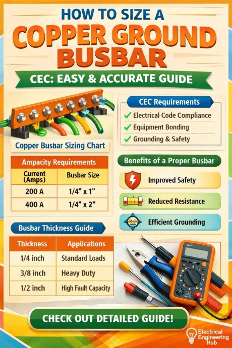
Table of Contents
Table of Contents
Whether you are working on a switchboard, panelboard, or grounding system, this article will help you calculate the right copper busbar dimensions.
Copper Busbar Sizes Chart
The table below shows commonly used copper ground busbar sizes.
| Width (mm) | Thickness (mm) | Area (mm²) |
|---|---|---|
| 20 | 3 | 60 |
| 25 | 3 | 75 |
| 25 | 6 | 150 |
| 30 | 6 | 180 |
| 40 | 6 | 240 |
| 50 | 6 | 300 |
| 50 | 10 | 500 |
These sizes are often used in electrical panels and grounding pits.
Quick Method to Size a Copper Ground Busbar CEC
For practical installations, many professionals follow conductor equivalency.
If your grounding conductor is:
| Ground Conductor Size | Recommended Busbar |
|---|---|
| 35 mm² | 25 × 3 mm |
| 70 mm² | 25 × 6 mm |
| 120 mm² | 30 × 6 mm |
| 240 mm² | 50 × 6 mm |
This method saves time in field work.
For faster calculations, you can use a dedicated busbar size calculator to verify dimensions instantly.
Why Ground Busbar Sizing Matters
A ground busbar acts as a common connection point for grounding conductors. Its main job is to safely carry fault currents to earth.
Proper busbar sizing helps in:
- Reducing fault path resistance
- Preventing excessive temperature rise
- Maintaining system stability
- Meeting CEC grounding requirements
- Protecting equipment and personnel
When you Size a Copper Ground Busbar CEC, the focus should always be on fault current capacity and conductor compatibility.
CEC Requirements for Ground Busbars
The Canadian Electrical Code provides guidance for grounding conductors and bonding conductors. While the CEC does not always directly specify exact busbar dimensions, it requires the grounding busbar to have equal or greater current-carrying capacity than connected grounding conductors.
Key CEC considerations include:
| CEC Factor | Importance |
|---|---|
| Fault current magnitude | Determines thermal stress |
| Fault clearing time | Impacts heat generation |
| Material type | Copper is highly conductive |
| Busbar thickness | Affects ampacity |
| Mechanical strength | Supports conductor termination |
Copper is the preferred material because of its high conductivity and corrosion resistance.
Factors That Affect Ground Busbar Size
Before you Size a Copper Ground Busbar CEC, consider these factors.
Available Fault Current
The higher the fault current, the larger the busbar must be.
For example:
| Fault Current | Typical Busbar Requirement |
|---|---|
| 10kA | Small copper busbar |
| 25kA | Medium copper busbar |
| 50kA+ | Large copper busbar |
Fault Duration
Busbars can withstand high fault currents for short durations. The longer the fault, the more heat builds up.
Common fault clearing times:
- 0.5 seconds
- 1 second
- 3 seconds
Number of Ground Conductors
More connected grounding wires require more termination space.
Busbar Mounting Type
Wall-mounted, panel-mounted, or insulated stand-off mounting affects heat dissipation.
Standard Formula to Size a Copper Ground Busbar CEC
A common thermal formula for copper busbar sizing is:
A = I√t / k
Where:
| Symbol | Meaning |
|---|---|
| A | Cross-sectional area (mm²) |
| I | Fault current (A) |
| t | Fault duration (seconds) |
| k | Material constant (143 for copper) |
This formula helps determine the minimum required cross-section. For quick calculation use our busbar sizing tool here.
How to Size a Copper Ground Busbar CEC (Example Calculation)
Suppose:
- Fault current = 20,000A
- Fault time = 1 second
Calculation:
A = 20,000 × √1 / 143
A = 139.86 mm²
This means the busbar should be at least 140 mm².
A practical selection may be:
- 25 mm × 6 mm = 150 mm²
This meets the requirement safely.
Key Takeaways
Here are the main points to remember:
- Always match busbar thermal capacity with fault current
- Copper busbars offer excellent conductivity and durability
- Fault clearing time is critical for thermal sizing
- CEC compliance requires proper grounding continuity
- Use practical standard sizes for easy installation
- Leave enough space for future grounding conductor additions
Correctly planning before installation improves safety and reduces future modifications.
Installation Tips for Copper Ground Busbars
After you Size a Copper Ground Busbar CEC, proper installation is equally important.
Use Proper Supports
Busbars should be firmly mounted on insulated supports.
Maintain Adequate Spacing
Keep enough clearance between live conductors and grounding bars.
Prevent Corrosion
Apply anti-oxidant compound where needed.
Tighten Connections Correctly
Loose grounding connections increase resistance.
Label the Busbar
Clear labeling improves maintenance and inspection.
Common Mistakes to Avoid
Many installers make these errors:
- Ignoring fault current calculations
- Selecting busbars based only on conductor size
- Using low-grade copper material
- Overcrowding conductor terminations
- Poor mounting arrangements
Avoiding these mistakes ensures long-term reliability.
Copper Busbar vs Aluminum Busbar for Grounding
Although aluminum is cheaper, copper is usually better for grounding.
| Feature | Copper | Aluminum |
|---|---|---|
| Conductivity | High | Medium |
| Corrosion resistance | Excellent | Good |
| Strength | High | Lower |
| Size required | Smaller | Larger |
| Cost | Higher | Lower |
Copper remains the best option for critical grounding systems.
Related Guide & Tools
- Electrical Bus Bar types and Applications
- Busbar Size Calculator According to IEC and NEC
- NEC vs IEC vs CEC Busbar Sizing
Final Thoughts
To Size a Copper Ground Busbar CEC correctly, you need to balance safety, code compliance, and practical installation needs. The best approach is to start with fault current calculations, apply the thermal formula, and then select a standard copper busbar size that meets or exceeds the requirement.
Ground busbars are not just metal strips. They are a major part of electrical safety and system reliability. A properly sized grounding busbar protects equipment, supports fault clearing, and ensures compliance with CEC standards.
FAQs
What is the minimum copper busbar size for grounding?
It depends on fault current and conductor size. Small systems may use 25 × 3 mm, while larger systems require bigger sizes.
Does CEC provide exact busbar dimensions?
CEC mainly provides grounding conductor requirements. Busbar sizing is usually based on equivalent conductor ampacity and fault current withstand.
Can I use aluminum busbars for grounding?
Yes, but copper is preferred because of better conductivity and corrosion resistance.
How do I calculate fault current for busbar sizing?
Fault current is usually determined from transformer ratings, system impedance, and utility data.
Is busbar thickness more important than width?
Both matter because the total cross-sectional area determines current-carrying capacity. Thickness also improves mechanical strength.
Find also about Busbar Sizing Rule of Thumb: Practical Engineer’s Guide for Accurate Panel Busbar Selection
Get new guides in your feed. Follow Electrical Insights on LinkedIn for new electrical standards guides, calculators and design tips from Azad Circuit Hub.
#HowToSizeACopperGroundBusbarCEC,#CopperGroundBusbar,#GroundBusbarSizing,#CECStandards,#ElectricalGrounding,#BusbarCalculation,#CopperBusbarDesign,#GroundingSystem,#ElectricalSafety,#BusbarSizingGuide
