
3 Phase Cable Size Calculator for UK: CSA & BS 7671 Guide
Selecting the correct cable size is essential for safety, energy efficiency, and compliance with the UK Wiring Regulations. A 3 Phase Cable Size Calculator for UK simplifies this process by calculating the minimum conductor size based on load current, installation method, voltage drop, cable length, ambient temperature, grouping factors, and insulation type.
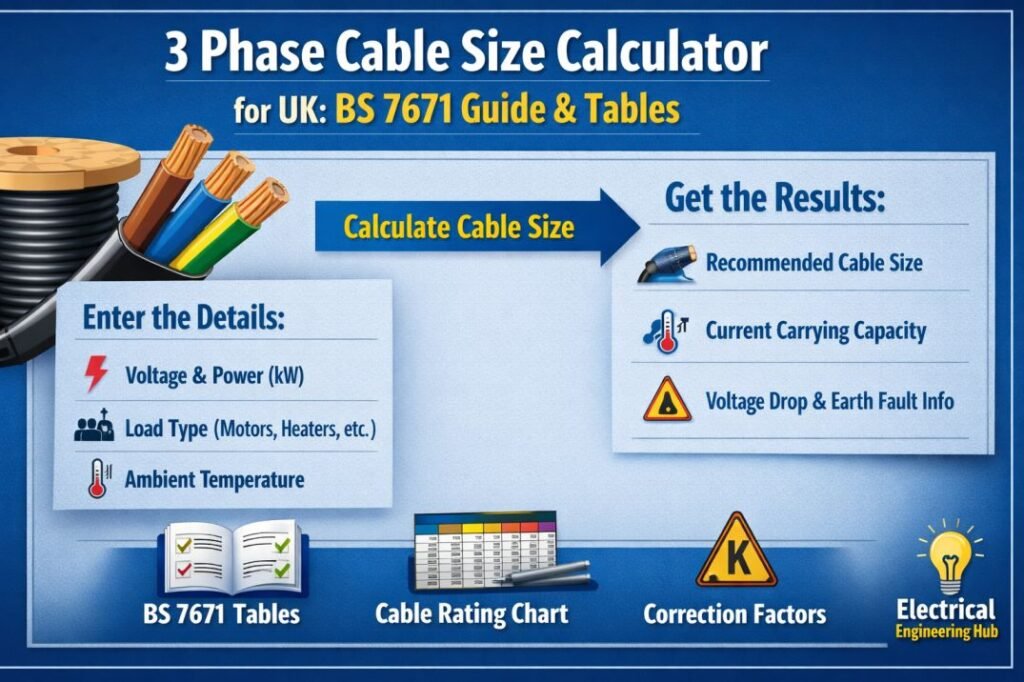
Table of Contents
Table of Contents
Looking for something more specific?
Sizing SWA or armoured cable? → Armoured Cable Size Calculator
Need Doncaster Cables data or specs? → Doncaster Cable Size Calculator
Working to AS/NZS (Australian) standards? → Earth Cable Size Calculator (AS/NZS)
Sizing for motors specifically? → Motor Cable Size Calculator
International project (IEC/NEC, not UK)? → 3 Phase Cable Size Calculator (International)
3 Phase Cable Size Calculator UK
3 Phase Cable Size Calculator UK
Estimate the correct conductor size for a balanced three-phase circuit based on load current, distance, voltage drop limits, and installation conditions.
Load Details
Cable & Installation
How to Use This Calculator
- Choose input mode. Enter the load current directly if you already know it, or switch to power mode and enter kW/HP, power factor, and efficiency.
- Select system voltage. Pick your line-to-line voltage from the list, or choose Custom to type any value.
- Enter cable length. Use the one-way distance from the source to the load, measured in meters.
- Set the allowed voltage drop. Three percent is a safe general target; use one percent for sensitive electronic or control loads.
- Pick installation conditions. Conductor material, installation method, insulation rating, ambient temperature, and circuit grouping all affect the final ampacity rating.
- Click Calculate. The tool checks every standard wire size against both your current-carrying requirement and your voltage drop limit, then recommends the smallest size that satisfies both.
- Review the comparison table. It shows which sizes pass or fail so you can see how much margin the recommended size has.
Technical Notes
Three-phase circuits are sized against two independent checks: the conductor’s current-carrying capacity (ampacity) and the permissible voltage drop over the run length. The larger of the two requirements always governs the final recommendation, which is why a long, lightly loaded feeder can require a bigger conductor than its current alone would suggest.
Ampacity ratings depend on the insulation temperature class, the ambient temperature around the cable, and how many other current-carrying conductors share the same conduit or tray. Higher ambient temperatures and more grouped circuits both reduce how much current a given conductor can safely carry, so the calculator applies correction factors before comparing against your load current.
Voltage drop becomes more significant as cable length increases and is also affected by conductor material, since aluminum has a notably higher resistance than copper for the same cross-section. This is why aluminum runs typically need to step up one or two sizes compared to an equivalent copper installation.
Direct burial and free-air installation conditions carry different heat dissipation characteristics than enclosed conduit, which is reflected in the ampacity comparison table. Always treat this tool as a planning aid; final conductor selection should be verified against the wiring regulation or standard applicable in your country (such as NEC, IEC 60364, or local utility code) and confirmed by a qualified electrical engineer before installation.
Find more Electrical Engineering Tools for easy electrical calculations and estimations.
| Parameter | Description |
|---|---|
| System Voltage | 400V three-phase (with optional custom voltage) |
| Load (kW, kVA or Current) | Multiple input methods |
| Power Factor | Adjustable from 0.6–1.0 |
| Cable Length | One-way length in metres |
| Installation Method | Method A, B, C, E and other BS 7671 reference methods |
| Conductor Material | Copper or Aluminium |
| Insulation Type | PVC (70°C), XLPE (90°C), LSZH |
| Ambient Temperature | Automatic correction factors |
| Grouped Circuits | Apply BS 7671 grouping factors |
| Thermal Insulation | Partial or complete insulation correction |
| Maximum Voltage Drop | User selectable (3% or 5%) |
| Short Circuit Check | Optional conductor verification |
| Results | Cable size, voltage drop, design current, corrected current capacity and compliance status |
A calculator with these features removes the need to manually reference multiple BS 7671 Appendix 4 tables while improving accuracy and saving considerable design time
What Is a 3 Phase Cable Size Calculator for UK?
A 3 Phase Cable Size Calculator for UK is a design tool that determines the appropriate cable cross-sectional area for three-phase electrical installations in accordance with BS 7671 (18th Edition IET Wiring Regulations).
Unlike generic international cable sizing calculators, a UK-specific calculator applies the current-carrying capacities, correction factors, and voltage drop requirements defined within BS 7671. It ensures that the selected cable can safely carry the design current without exceeding temperature limits or permissible voltage drop.
Learn more about how to obtain electrical periodic inspection certificates in UK
The calculator evaluates several important design parameters, including:
- Load current
- Cable length
- Installation method
- Conductor material
- Insulation type
- Ambient temperature
- Grouping of circuits
- Thermal insulation
- Allowable voltage drop
The result is a cable size that satisfies both electrical performance and regulatory compliance.
Common applications include:
- Commercial buildings
- Industrial plants
- Distribution boards
- Three-phase motors
- HVAC systems
- Manufacturing facilities
- Agricultural installations
- EV charging infrastructure
Explore Top 30 UK G99 Grid Connection Interview Questions
What Is Cable CSA (Cross-Sectional Area)?
Cable CSA (Cross-Sectional Area) is the area of a conductor measured in square millimetres (mm²). In electrical design, the terms cable size, CSA, and cross-sectional area all refer to the same conductor dimension used for current-carrying capacity and voltage drop calculations.
A 3 Phase Cable Size Calculator for UK determines the correct CSA based on load current, cable length, installation method, and BS 7671 requirements.
| Term | Meaning |
|---|---|
| CSA | Conductor cross-sectional area (mm²) |
| Cable Size | Common name for CSA |
| Cross-Sectional Area | Technical measurement of conductor size |
Choosing the correct CSA improves safety, efficiency, and compliance with UK wiring standards.
BS 7671 Requirements for 3-Phase Cable Sizing
BS 7671 (18th Edition) establishes the rules for selecting conductors in UK electrical installations. The objective is to ensure cables remain within their temperature rating while maintaining acceptable voltage at the load.
Several sections of BS 7671 are particularly important during cable selection.
Current-Carrying Capacity
Appendix 4 contains the current-carrying capacity tables used throughout the design process. These tables provide permissible current ratings for different cable sizes under various installation methods.
The current rating depends on:
- Installation method
- Conductor material
- Insulation rating
- Number of loaded conductors
- Ambient temperature
The selected cable must have a corrected current-carrying capacity greater than the design current.
Know more about UK G100 HV Grid Standards
Voltage Drop Limits
BS 7671 specifies maximum recommended voltage drop limits from the origin of the installation to the point of use.
| Circuit Type | Maximum Voltage Drop |
|---|---|
| Lighting Circuits | 3% |
| Other Power Circuits | 5% |
For a standard 400V three-phase supply, these limits are approximately:
| Circuit | Maximum Voltage Drop |
|---|---|
| Lighting | 12V |
| Power | 20V |
Where long cable runs are involved, voltage drop often becomes the governing factor rather than current-carrying capacity.
Correction Factors
The tabulated current ratings are based on standard reference conditions. Real installations usually require correction factors for:
- Higher ambient temperatures
- Multiple grouped circuits
- Thermal insulation
- Installation environment
These correction factors are applied before confirming the final cable size.
Find all about Ofgem Electricity Regulations
3-Phase Cable Sizing Formula
Cable sizing begins by calculating the design current. Once the current is known, voltage drop and current-carrying capacity are verified using BS 7671 tables.
Design Current Formula
For three-phase systems:
I = P / (√3 × V × PF)
Where:
| Symbol | Description |
|---|---|
| I | Current (A) |
| P | Power (W) |
| V | Line Voltage (V) |
| PF | Power Factor |
This formula converts electrical power into the line current flowing through the cable.
Voltage Drop Formula
For three-phase circuits:
Vd = √3 × I × R × L / 1000
Where:
| Symbol | Description |
|---|---|
| Vd | Voltage Drop (V) |
| I | Current (A) |
| R | Cable resistance (mV/A/m) |
| L | One-way cable length (m) |
After calculating the voltage drop, compare the result with the BS 7671 limits of 3% for lighting circuits or 5% for other circuits.
If either the current capacity or voltage drop exceeds the allowable limit, the next larger cable size should be selected.
Find the best three phase transformer suppliers in UK
BS 7671 Cable CSA / Current-Carrying Capacity Table (Copper, 400V, 3-Phase)
The following table is based on the methodology used in BS 7671 Appendix 4. Actual values vary depending on conductor insulation, installation conditions, and manufacturer data. Always verify final designs using the latest edition of BS 7671.
| Cable Size (mm²) | Method A (Enclosed in Conduit) | Method C (Clipped Direct) | Method E (Free Air) |
|---|---|---|---|
| 1.5 | 14 A | 20 A | 23 A |
| 2.5 | 19 A | 27 A | 30 A |
| 4 | 25 A | 37 A | 40 A |
| 6 | 32 A | 47 A | 52 A |
| 10 | 44 A | 65 A | 71 A |
| 16 | 57 A | 87 A | 94 A |
| 25 | 76 A | 114 A | 119 A |
| 35 | 94 A | 141 A | 148 A |
| 50 | 113 A | 176 A | 184 A |
| 70 | 143 A | 221 A | 229 A |
| 95 | 171 A | 265 A | 275 A |
| 120 | 197 A | 305 A | 317 A |
| 150 | 225 A | 350 A | 363 A |
| 185 | 256 A | 402 A | 415 A |
| 240 | 300 A | 475 A | 490 A |
Understanding Installation Methods
| Installation Method | Description | Typical Application |
|---|---|---|
| Method A | Cable enclosed in conduit or trunking within thermally insulating walls | Residential and concealed wiring |
| Method C | Cable clipped directly to a surface | Industrial and commercial installations |
| Method E | Cable installed in free air with unrestricted ventilation | Cable trays, ladder systems and open-air installations |
Method C generally provides a higher current-carrying capacity than Method A because heat dissipates more effectively. Method E offers the highest ratings due to maximum air circulation around the cable.
Selecting the correct installation method is critical because choosing the wrong reference method can lead to undersized conductors or unnecessary oversizing, affecting both safety and project cost.
Derating Factors for UK Installations
The current-carrying capacities listed in BS 7671 Appendix 4 are based on standard reference conditions. In practice, many installations differ from these conditions, so correction (derating) factors must be applied before selecting the final cable size.
The corrected current-carrying capacity is calculated as:
Iz ≥ Ib ÷ (Ca × Cg × Ci)
Where:
| Symbol | Description |
|---|---|
| Iz | Required tabulated current-carrying capacity |
| Ib | Design current |
| Ca | Ambient temperature correction factor |
| Cg | Grouping correction factor |
| Ci | Thermal insulation correction factor |
If the corrected current exceeds the selected cable’s tabulated rating, the next larger cable size should be chosen.
Ambient Temperature Correction (BS 7671 Table 4B1)
Higher ambient temperatures reduce a cable’s ability to dissipate heat, lowering its safe current-carrying capacity.
PVC Insulated Cables (70°C)
| Ambient Temperature | Correction Factor |
|---|---|
| 25°C | 1.03 |
| 30°C | 1.00 |
| 35°C | 0.94 |
| 40°C | 0.87 |
| 45°C | 0.79 |
| 50°C | 0.71 |
| 55°C | 0.61 |
| 60°C | 0.50 |
Use our online tool Heat Pump KWh Calculator UK Free
Grouping Factor (BS 7671 Table 4C1)
When multiple circuits are installed together, heat builds up between cables, reducing their current-carrying capacity.
| Number of Circuits | Grouping Factor |
|---|---|
| 1 | 1.00 |
| 2 | 0.80 |
| 3 | 0.70 |
| 4 | 0.65 |
| 5 | 0.60 |
| 6 | 0.57 |
| 7–9 | 0.54 |
| 10–12 | 0.52 |
| 13–20 | 0.45 |
Thermal Insulation Correction (BS 7671 Table 4C2)
Cables surrounded by thermal insulation cannot release heat efficiently, requiring further derating.
| Installation Condition | Typical Correction Factor |
|---|---|
| No insulation | 1.00 |
| Partially surrounded | 0.89 |
| Fully surrounded for short distance | 0.77 |
| Fully surrounded for long distance | Refer to BS 7671 design tables |
Always identify every applicable correction factor before selecting the cable. Ignoring even one factor can result in an undersized cable that overheats during operation.
Use our online tool Fish Tank Electricity Cost Calculator UK
Worked Example: Sizing a 3-Phase Cable per BS 7671
The following example demonstrates a practical cable sizing calculation using BS 7671.
Design Data
| Parameter | Value |
|---|---|
| Supply Voltage | 400V |
| Load | 45 kW |
| Power Factor | 0.90 |
| Cable Length | 55 m |
| Installation Method | Method C (Clipped Direct) |
| Ambient Temperature | 30°C |
| Number of Grouped Circuits | 3 |
| Cable Type | Copper PVC |
| Circuit Type | Power |
Step 1: Calculate Design Current
Using the three-phase current formula:
I = P ÷ (√3 × V × PF)
I = 45,000 ÷ (1.732 × 400 × 0.90)
Design Current = 72.2 A
Step 2: Apply Correction Factors
Ambient temperature (30°C):
Ca = 1.00
Three grouped circuits:
Cg = 0.70
No thermal insulation:
Ci = 1.00
Required tabulated current:
Iz = 72.2 ÷ (1.00 × 0.70 × 1.00)
Iz = 103.1 A
Step 3: Select Cable Size
From the BS 7671 Method C table:
| Cable Size | Current Rating |
|---|---|
| 16 mm² | 87 A |
| 25 mm² | 114 A |
A 16 mm² cable is insufficient because its rating is below the required 103.1 A.
A 25 mm² copper cable is suitable because its current rating is 114 A.
Explore all about Best Surge Protection Extension Lead UK 2026
Step 4: Check Voltage Drop
Using:
Vd = √3 × I × R × L ÷ 1000
Assuming a voltage drop value of 1.75 mV/A/m for 25 mm² copper:
Vd = 1.732 × 72.2 × 1.75 × 55 ÷ 1000
Voltage Drop ≈ 12.0 V
Percentage voltage drop:
12 ÷ 400 × 100 = 3.0%
Since this is below the BS 7671 limit of 5% for power circuits, the cable complies.
Final Selection
| Item | Result |
|---|---|
| Design Current | 72.2 A |
| Corrected Current Capacity Required | 103.1 A |
| Selected Cable | 25 mm² Copper PVC |
| Installation Method | Method C |
| Voltage Drop | 3.0% |
| BS 7671 Compliance | Yes |
This example illustrates why correction factors are just as important as the initial current calculation.
Common Mistakes in UK 3-Phase Cable Sizing
Even experienced installers can make errors if important design checks are overlooked. The following mistakes are among the most common.
Ignoring Grouping Factors
Installing several circuits together without applying the grouping correction factor can significantly reduce the cable’s current-carrying capacity, leading to overheating.
Using Single-Phase Tables
Three-phase circuits have different current calculations and voltage drop characteristics. Always use the appropriate BS 7671 tables for three-phase installations.
Forgetting Voltage Drop
A cable may satisfy the current-carrying requirement but still fail the voltage drop limit, especially on long cable runs. Both checks are essential.
Overlooking Ambient Temperature
Electrical rooms, plant areas, roof spaces, and outdoor enclosures often operate above the standard reference temperature. Applying the correct ambient temperature factor helps prevent undersized cable selection.
Ignoring Neutral and Protective Conductors
The phase conductor is only one part of the circuit design. Neutral conductor sizing, protective conductor requirements, fault protection, and earth fault loop impedance should also comply with BS 7671.
3-Phase Cable Size Calculator vs. Manual Calculation
A manual cable sizing calculation requires consulting multiple BS 7671 Appendix 4 tables, applying correction factors, calculating design current, checking voltage drop, and verifying compliance. This process is accurate but can be time-consuming, particularly for complex installations.
A 3 Phase Cable Size Calculator for UK automates these steps in seconds. After entering the project details, the calculator applies the appropriate correction factors, calculates voltage drop, and recommends a compliant cable size. This reduces the chance of calculation errors and makes it easier to compare different installation methods or cable types during the design stage.
Related UK Cable Calculators
If you are designing electrical installations in accordance with BS 7671, the following tools can further simplify your calculations:
| Calculator | Purpose |
|---|---|
| Earth Cable Size Calculator | Calculates protective conductor sizes for UK and international standards. |
| Cable CSA Calculator UK | Determines the required conductor cross-sectional area based on load and installation conditions. |
| Doncaster Cable Size Calculator | Compares cable selections using manufacturer-based current ratings and voltage drop data. |
Using these calculators alongside your 3 Phase Cable Size Calculator for UK helps ensure every part of the electrical installation is correctly designed and fully compliant with the latest wiring regulations.
Frequently Asked Questions
What is the formula for 3-phase cable size in the UK?
The design current is calculated using I = P ÷ (√3 × V × PF). The calculated current is then checked against BS 7671 Appendix 4 current-carrying capacity tables, with correction factors and voltage drop verification applied before selecting the cable size.
Does BS 7671 require different cable sizes than IEC 60364?
The design principles are similar, but BS 7671 uses its own reference methods, current-carrying capacity tables, correction factors, and voltage drop requirements. As a result, the recommended cable size may differ from an IEC 60364 calculation.
What voltage drop is allowed for 3-phase circuits under BS 7671?
BS 7671 recommends a maximum voltage drop of 3% for lighting circuits and 5% for other power circuits, measured from the origin of the installation to the point of use.
How do I account for grouped circuits when sizing cable?
Apply the grouping correction factor from BS 7671 Table 4C1. Divide the design current by the appropriate correction factors before selecting the cable from the Appendix 4 current-carrying capacity tables. This ensures the cable remains within its temperature rating under grouped installation conditions.
What does CSA mean for cables?
CSA (Cross-Sectional Area) is the area of the conductor inside a cable, measured in mm². It indicates how much current the cable can safely carry and influences voltage drop and resistance. A larger CSA generally supports higher current loads.
How do I calculate cable CSA in mm²?
Cable CSA is calculated based on the conductor diameter using the formula: CSA = π × (d/2)² for a solid conductor. In practical electrical design, CSA is selected using current rating, voltage drop, installation method, and applicable standards such as IEC or BS 7671.
Follow Us on Social:
Subscribe our Newsletter on Electrical Insights for latest updates from Electrical Engineering Hub
3PhaseCableSizeCalculatorForUK, #BS7671, #CableSizing, #ElectricalEngineering, #UKElectricians, #VoltageDrop, #ElectricalDesign, #WiringRegulations, #PowerDistribution, #ElectricalCalculators
3 Phase Cable Size Calculator for UK: CSA & BS 7671 Guide : Electrical Engineering Hub

Free 3 phase cable size calculator for UK installations per BS 7671. Calculate cross-sectional area, voltage drop, and derating factors with worked examples on 3 phase cable CSA calculator for UK
Price Currency: USD
Operating System: Web Browser
Application Category: UtilitiesApplication
