
Armoured Cable Size Calculator
Choosing the correct cable is important for safe and reliable electrical installations. An undersized cable can overheat, cause excessive voltage drop, and reduce equipment performance. An oversized cable may increase installation cost without providing a practical benefit. An Armoured Cable Size Calculator helps you select a suitable cable size by considering load current, cable length, voltage, installation method, conductor material, and allowable voltage drop.
For common low-voltage installations, steel wire armoured (SWA) cables are widely used for power distribution, industrial equipment, outdoor circuits, pumps, motors, and underground runs. The final cable selection should always be checked against the applicable standard and the manufacturer’s current-carrying capacity tables.
Armoured Cable Size Calculator
Cable Sizing Reference Tool
Armoured Cable Size Calculator
Work out the minimum steel wire armoured (SWA) cable cross-section for a given load, run length and installation condition, checked against both current-carrying capacity and voltage drop.
Load and installation inputs
Cables bunched, clipped together or sharing a tray reduce each other’s rating. Leave at 1 for a single isolated circuit.
Result
How to use this calculator
- Choose whether to enter the load as a current in amps, or as a power in kW with a power factor. The tool converts power to current for you.
- Set the supply system. Single phase assumes 230 V, three phase assumes 400 V, and either voltage can be overridden manually if your supply differs.
- Pick the conductor material, number of cores, and the one-way length of the cable run from source to load.
- Set the maximum voltage drop you will allow over that run. A common starting point is 4 percent of nominal voltage for the full installation, split between distribution and final circuits.
- Describe how the cable will be installed: clipped to a surface, in free air, in conduit, or buried, plus the ambient temperature and how many other loaded circuits run alongside it.
- Select Calculate. The tool checks every standard size in turn and returns the smallest one that satisfies both the thermal rating and the voltage drop limit, along with which check decided the outcome.
What the calculation is checking
Two separate limits govern cable size, and the smaller cable that still passes both is not always determined by the same one. The first is thermal: the cable has to carry the design current continuously without its insulation running hotter than it is rated for, once temperature, grouping and installation conditions are taken into account.
The second is voltage drop: even a cable that is thermally adequate can let too much voltage disappear along a long run, leaving equipment at the far end underpowered. Longer runs and higher currents push this limit up, which is why long, lightly loaded runs are often sized by voltage drop rather than heat.
The result shown reports which of the two limits set the final size, so you can see immediately whether shortening the run, reducing grouping, or improving ventilation would let you drop to a smaller and cheaper cable.
Figures used in this tool (current ratings, voltage drop factors, cable dimensions and weights) are indicative reference values for standard multicore XLPE or PVC insulated steel wire armoured cable and are provided for preliminary sizing only. Local standards, manufacturer datasheets and site-specific conditions can all shift the correct answer. Always verify the final cable selection against the official current edition of the applicable wiring regulations or standard, and against the manufacturer’s published data, before specifying or installing.
| Cable Selection Factor | Typical Requirement | Why It Matters |
|---|---|---|
| Conductor | Copper or aluminium | Determines resistance and ampacity |
| System voltage | 230 V / 400 V | Used for load and voltage-drop calculations |
| Frequency | 50 Hz / 60 Hz | Important for AC systems |
| Voltage drop | Usually 3% or 5% design limit | Prevents excessive voltage loss |
| Cable type | SWA / XLPE / PVC | Affects thermal rating |
| Installation | Buried, clipped, tray, duct | Changes current-carrying capacity |
| Ambient temperature | Common reference: 30°C | Higher temperature reduces ampacity |
| Conductor size | 1.5 mm² and upward | Selected from calculated design current |
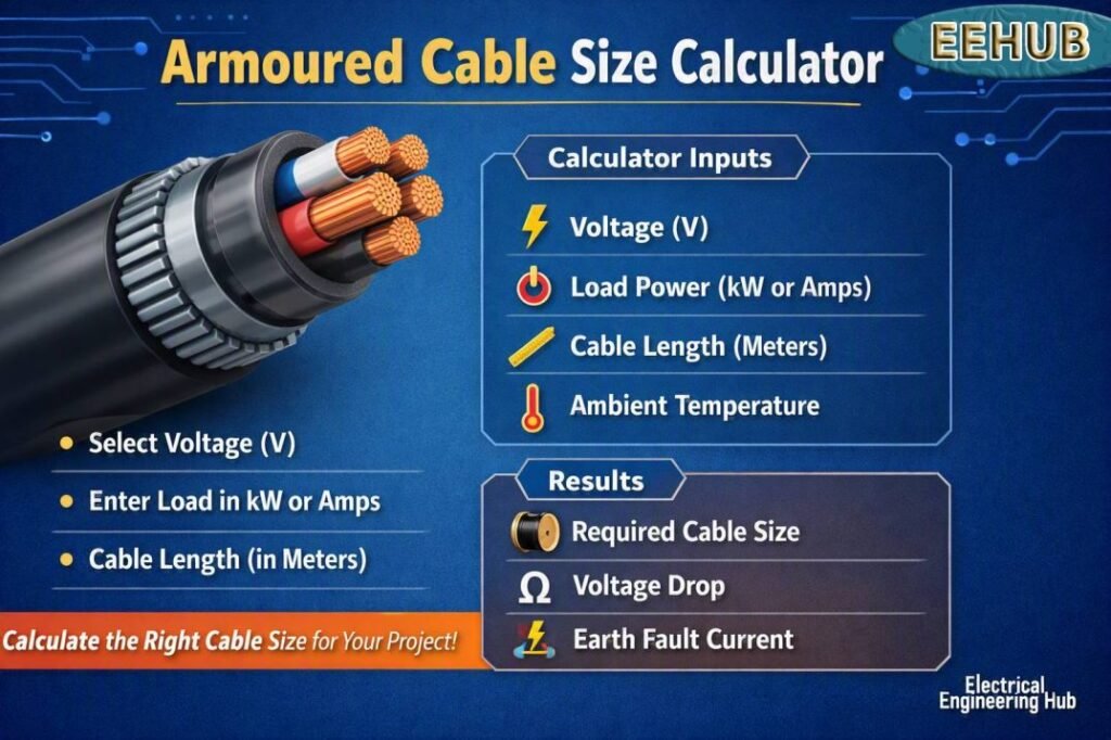
Table of Contents
Table of Contents
What Is an Armoured Cable Size Calculator?
An Armoured Cable Size Calculator is a design tool used to estimate the conductor size required for a particular electrical circuit. It normally starts with the connected load and converts the load into design current.
For a three-phase load:
I = P ÷ (√3 × V × PF)
Where:
- I = load current in amperes
- P = power in watts
- V = line-to-line voltage
- PF = power factor
For a single-phase circuit:
I = P ÷ (V × PF)
For example, a 15 kW three-phase motor operating at 400 V with a power factor of 0.85 has an approximate full-load current of:
15,000 ÷ (1.732 × 400 × 0.85) ≈ 25.5 A
The selected cable must then be checked for current-carrying capacity, voltage drop, short-circuit withstand, protective-device coordination, and installation conditions.
If you are also sizing conductors for different types of three-phase loads, our 3 phase cable size calculator can provide a useful starting point for comparing cable requirements.
Armoured Cable Size Calculation Method
A practical cable-sizing process normally follows several stages.
1. Calculate the Design Current
First determine the expected continuous load current. For motors, pumps, heaters, compressors, and other equipment, use the equipment nameplate data where available.
For a 400 V three-phase system:
I = kW × 1000 ÷ (1.732 × 400 × PF)
For example, a 30 kW load at 0.9 power factor requires approximately:
30,000 ÷ (1.732 × 400 × 0.9) = 48.1 A
This value is the starting point for selecting an armoured cable.
2. Apply Cable Rating Factors
The cable's published rating is not always the actual permissible current at the installation site. Correction factors may be required for:
- Ambient temperature
- Soil thermal resistivity
- Cable grouping
- Installation depth
- Duct installation
- Thermal insulation
- Number of loaded conductors
- Ground installation conditions
The effective current-carrying capacity can be considered using:
Iz = It × C1 × C2 × C3 × ...
Where It is the tabulated cable rating and the C values represent applicable correction factors.
This is why an armoured cable calculator should not rely on conductor size alone.
Armoured Cable Ampacity and Rating
Actual cable ratings vary according to construction, insulation, installation method, conductor material, and manufacturer. The following values are useful typical reference figures for commonly used copper XLPE/SWA/PVC cables under suitable reference conditions.
| Copper SWA Cable | Typical Current Rating* |
|---|---|
| 1.5 mm² | About 18–23 A |
| 2.5 mm² | About 24–31 A |
| 4 mm² | About 32–42 A |
| 6 mm² | About 41–52 A |
| 10 mm² | About 57–72 A |
| 16 mm² | About 76–94 A |
| 25 mm² | About 101–119 A |
| 35 mm² | About 125–145 A |
| 50 mm² | About 150–175 A |
| 70 mm² | About 190–220 A |
| 95 mm² | About 230–260 A |
| 120 mm² | About 265–295 A |
| 150 mm² | About 300–330 A |
| 185 mm² | About 340–370 A |
| 240 mm² | About 390–430 A |
*Typical ranges only. Actual ratings must be taken from the applicable cable manufacturer's data and installation method.
These values show why an armoured cable rating calculator needs more information than simply entering the load in kW.
Armoured Cable Voltage Drop Calculator
Voltage drop is one of the most important checks after current capacity. A cable may safely carry the load current but still be unsuitable because the voltage at the equipment is too low.
For a simplified single-phase calculation:
Vd = 2 × I × L × R
For a three-phase circuit:
Vd = √3 × I × L × R
Where:
- Vd = voltage drop
- I = current
- L = one-way cable length
- R = conductor resistance per unit length
In practical cable design, manufacturers often provide voltage-drop figures in mV/A/m. These values make calculations easier:
Vd = mV/A/m × I × L ÷ 1000
For example, if a cable has a voltage-drop value of 1.9 mV/A/m, carries 50 A, and is 100 m long:
Vd = 1.9 × 50 × 100 ÷ 1000 = 9.5 V
At 400 V, this represents approximately 2.38%.
A dedicated armoured cable voltage drop calculator should therefore include both cable length and operating current rather than relying only on ampacity.
Armoured Cable Load Calculator
An armoured cable load calculator works in the opposite direction. Instead of starting with cable size, you can estimate how much electrical load a particular cable can support.
For a three-phase system:
kW = √3 × V × I × PF ÷ 1000
For example, a 400 V cable carrying 63 A at 0.9 power factor can theoretically supply:
1.732 × 400 × 63 × 0.9 ÷ 1000 ≈ 39.3 kW
This does not mean a 63 A cable should automatically be used for a 39.3 kW load. The cable rating, protective device, installation conditions, voltage drop, and continuous-load requirements must still be checked.
SWA Armoured Cable Calculator
An SWA armoured cable calculator is particularly useful for industrial and outdoor circuits. SWA generally means steel wire armoured cable, commonly used where mechanical protection is required.
Typical applications include:
- Submain distribution
- Industrial machinery
- Water pumps
- Solar power systems
- Outdoor lighting
- Workshop supplies
- Underground feeders
- Motor circuits
- Generator connections
For buried cables, thermal conditions can have a major effect on ampacity. The installation environment should therefore be entered or selected correctly before relying on a calculated result.
Armoured Cable Calculator UK Considerations
For UK installations, cable selection commonly involves BS 7671 requirements together with relevant manufacturer data and product standards. A UK armoured cable calculator should consider the design current, cable installation method, correction factors, voltage drop, earth fault loop conditions, and protective-device characteristics.
A commonly used design relationship is:
Ib ≤ In ≤ Iz
Where:
- Ib = design current
- In = protective device rating
- Iz = cable current-carrying capacity after correction factors
For example, if the design current is 42 A, a 50 A protective device may only be appropriate if the selected cable has an adequate corrected rating and the rest of the design checks pass.
If your project involves selecting conductors across residential, commercial, or industrial three-phase circuits, use our 3 phase cable size calculator to compare current, voltage, and cable-size requirements.
Armoured Cable Size Chart
A basic armoured cable size chart can help narrow down the initial selection.
| Armoured Cable Size | Typical Applications |
|---|---|
| 1.5–2.5 mm² | Lighting and small power |
| 4–6 mm² | Small machinery and larger circuits |
| 10–16 mm² | Subcircuits and medium loads |
| 25–50 mm² | Industrial feeders and large equipment |
| 70–120 mm² | High-current distribution |
| 150–240 mm² | Large industrial feeders |
The exact cable size should never be selected from this table alone. Installation conditions and voltage drop can require a larger conductor.
Armoured Cable Sizes and Conductor Material
Armoured cables are available with copper or aluminium conductors. Copper generally offers lower resistance and better conductivity, while aluminium can reduce cable weight and material cost for larger installations.
For long-distance feeders, aluminium cables may be attractive because the larger conductor cross-section can still provide economical power distribution. However, termination requirements, installation practices, mechanical properties, and manufacturer recommendations must be considered.
When comparing armoured cable sizes, always compare the actual electrical characteristics rather than assuming that two cables with the same nominal cross-sectional area will perform identically.
Electrical Armoured Cable Size Calculator: Worked Example
Consider a 45 kW, 400 V three-phase load operating at 0.9 power factor.
Design current:
I = 45,000 ÷ (1.732 × 400 × 0.9)
I ≈ 72.2 A
A suitable cable must therefore have a corrected current-carrying capacity above the required design current. Suppose a selected cable has a reference rating of 100 A, but installation correction factors reduce its effective rating to 82 A. It may still satisfy the ampacity requirement because 82 A is above 72.2 A.
The next checks should include voltage drop, short-circuit withstand, earth fault conditions, protective-device coordination, and termination ratings.
This example demonstrates why an electrical armoured cable size calculator should be treated as a design aid rather than a replacement for the complete cable-sizing procedure.
Armoured Cable Size Calculator UK vs General Cable Sizing
The basic electrical principles are similar worldwide, but design standards and permitted voltage-drop limits can differ.
| Factor | UK Installation | General IEC-Based Design |
|---|---|---|
| Common reference | BS 7671 | IEC standards/local regulations |
| Cable type | SWA widely used | Varies by region |
| Voltage | 230/400 V common | Depends on country |
| Correction factors | Required | Required |
| Voltage drop | Design-dependent | Design-dependent |
| Protective device | MCB/MCCB/fuse | Depends on installation |
| Manufacturer data | Essential | Essential |
Therefore, an armoured cable size calculator uk should be configured around the standards and installation practices applicable to the project.
Important Checks Before Selecting Cable Size
Before purchasing cable, check these factors:
- Confirm the load current.
- Identify single-phase or three-phase operation.
- Confirm operating voltage.
- Check the cable installation method.
- Apply correction factors.
- Calculate voltage drop.
- Check short-circuit withstand.
- Verify protective-device coordination.
- Check gland, lug, and termination compatibility.
- Confirm the manufacturer's published cable rating.
For longer cable runs, voltage drop can become the deciding factor even when the cable has sufficient ampacity.
Frequently Asked Questions
What is the best armoured cable size for a 50 amp load?
There is no universal answer. A 50 A load may require a 10 mm², 16 mm², or larger cable depending on installation method, conductor material, ambient conditions, cable length, and voltage-drop requirements. The cable should be selected from the manufacturer's rating tables after applying correction factors.
How do I calculate armoured cable size?
Calculate the design current first, then select a cable whose corrected current-carrying capacity is adequate. After that, verify voltage drop, short-circuit withstand, protective-device coordination, and installation requirements.
What is the difference between SWA and armoured cable?
SWA is a specific type of steel wire armoured cable. The term armoured cable is broader and can describe cables incorporating different forms of mechanical armour. SWA is particularly common in low-voltage power distribution.
Does cable length affect armoured cable size?
Yes. Longer cable runs produce greater voltage drop. Even when a cable can carry the required current, a larger conductor may be needed to keep voltage drop within the project's permitted limit.
Can I use an armoured cable size chart instead of calculation?
A chart is useful for preliminary selection, but it should not replace a complete cable calculation. Current capacity changes with installation conditions, temperature, grouping, cable construction, and conductor material.
Final Considerations
An Armoured Cable Size Calculator provides a fast way to estimate the conductor size required for a power circuit, but accurate selection requires more than matching load current to cable ampacity. Cable length, voltage drop, installation method, correction factors, short-circuit performance, and protective-device coordination all affect the final result.
The most reliable approach is to calculate the design current, select a suitable armoured cable size, verify its corrected current rating, and then perform voltage-drop and fault-current checks. Always confirm the final selection against the latest applicable electrical standard and the manufacturer's published data.
For larger distribution systems and three-phase feeders, our 3 phase cable size calculator can also help you evaluate cable requirements using load, voltage, current, and other key electrical parameters.
Get new guides in your feed. Follow Electrical Insights on LinkedIn for new electrical standards guides, calculators and design tips from Azad Circuit Hub.
Armoured Cable Size Calculator
Use our Armoured Cable Size Calculator to determine the correct cable size based on load current, voltage drop, installation method, and electrical standards.
Price Currency: USD
Operating System: Web Browser
Application Category: UtilitiesApplication
