AS/NZS 3000 Cable Sizing Table Explained (With Examples)
The AS/NZS 3000 Cable Sizing Table is a useful starting point when working on electrical installations in Australia and New Zealand, but cable selection is not based on conductor size alone. Current-carrying capacity, installation method, ambient temperature, voltage drop, grouping, insulation temperature, and protective devices all need to be considered.
AS/NZS 3000, commonly known as the Australian/New Zealand Wiring Rules, sets the installation requirements. Detailed cable selection and current-carrying capacity calculations are closely associated with AS/NZS 3008.1.1. Understanding how these standards work together helps electricians, engineers, and contractors select cables more reliably.
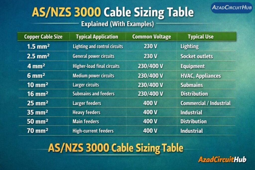
Table of Contents
Table of Contents
Quick Cable Sizing Reference
The following table provides a practical reference for common copper cable sizes. These values are not a substitute for the applicable standard tables because the allowable current changes with installation conditions.
| Copper Cable Size | Typical Application | Common Voltage | Typical Use |
|---|---|---|---|
| 1.5 mm² | Lighting and control circuits | 230 V | Lighting |
| 2.5 mm² | General power circuits | 230 V | Socket outlets |
| 4 mm² | Higher-load final circuits | 230/400 V | Equipment |
| 6 mm² | Medium power circuits | 230/400 V | HVAC, appliances |
| 10 mm² | Larger circuits | 230/400 V | Submains |
| 16 mm² | Submains and feeders | 230/400 V | Distribution |
| 25 mm² | Larger feeders | 400 V | Commercial/industrial |
| 35 mm² | Heavy feeders | 400 V | Industrial |
| 50 mm² | Main feeders | 400 V | Distribution |
| 70 mm² | High-current feeders | 400 V | Industrial |
A cable with a larger cross-sectional area does not automatically have the required current capacity for every installation. The installation method must be checked before selecting the final conductor size.
What Does the AS/NZS 3000 Cable Sizing Table Show?
In practice, electricians often use the phrase AS/NZS 3000 Cable Sizing Table when referring to cable selection information used alongside the Wiring Rules. However, it is important to distinguish between the standards.
AS/NZS 3000 provides the fundamental requirements for electrical installations, including protection against electric shock, wiring systems, voltage drop considerations, earthing, switchboards, and circuit protection.
AS/NZS 3008.1.1 provides detailed information for selecting cables based on factors such as:
- Current-carrying capacity
- Installation method
- Ambient temperature
- Cable grouping
- Thermal insulation
- Voltage drop
- Conductor material
- Insulation type
- Number of loaded conductors
This distinction matters when using online cable sizing charts. A simple table may show a cable’s nominal size, but the design still needs to satisfy the requirements of the applicable Australian or New Zealand standard.
Common Copper Cable Sizes and Applications
| Cable Size | Approximate Area | Common Electrical Application |
|---|---|---|
| 1.0 mm² | 1.0 mm² | Control and specialized circuits |
| 1.5 mm² | 1.5 mm² | Lighting |
| 2.5 mm² | 2.5 mm² | Power outlets |
| 4 mm² | 4 mm² | Higher-load equipment |
| 6 mm² | 6 mm² | Air conditioning and equipment |
| 10 mm² | 10 mm² | Submains |
| 16 mm² | 16 mm² | Submains and feeders |
| 25 mm² | 25 mm² | Distribution feeders |
| 35 mm² | 35 mm² | Industrial feeders |
| 50 mm² | 50 mm² | Main distribution |
| 70 mm² | 70 mm² | High-current feeders |
These are common nominal conductor sizes rather than universal ampacity ratings.
How to Use an AS/NZS 3000 Cable Sizing Table
Cable selection should normally start with the design current.
For a simple single-phase load, the approximate current can be calculated using:
I = P / V
Where:
- I = current in amperes
- P = load power in watts
- V = supply voltage
For a three-phase load:
I = P / (√3 × V × PF)
Where PF represents the power factor.
For example, consider a 7.2 kW single-phase load supplied at 230 V:
I = 7200 / 230 = 31.3 A
A cable should not simply be selected by finding a conductor that carries slightly more than 31.3 A. The engineer must also check the installation method, ambient conditions, grouping, voltage drop, protective device, and other applicable factors.
For practical design work, a cable sizing calculator as3008 can help organize these inputs before confirming the result against the applicable standard.
Example 1: Single-Phase 5 kW Load
Suppose a fixed load has a power rating of 5 kW and operates from a 230 V supply.
The design current is:
I = 5000 / 230 = 21.7 A
The next step is to determine the cable’s allowable current under its actual installation conditions.
Consider this simplified design process:
| Design Parameter | Example Value |
|---|---|
| Load | 5 kW |
| Supply | 230 V |
| Calculated current | 21.7 A |
| Conductor | Copper |
| Circuit type | Single phase |
| Installation | To be verified |
| Voltage drop | To be checked |
| Protection | To be selected |
If the cable is installed in a way that reduces its current-carrying capacity, a larger conductor may be required even though the calculated load current remains 21.7 A.
This is why an AS/NZS 3000 Cable Sizing Table should be treated as part of a complete design process rather than a simple amp-to-mm² lookup chart.
Example 2: Three-Phase Motor Load
Consider a 15 kW three-phase motor operating at 400 V with a power factor of 0.85.
The approximate full-load current is:
I = 15,000 / (1.732 × 400 × 0.85)
This gives approximately 25.5 A.
Motor circuits require additional consideration because starting current, motor protection, cable installation conditions, voltage drop, and equipment requirements can affect the final selection.
For three-phase Australian installations, a 3 phase cable size calculator australia can provide a useful preliminary check before the cable size is verified against the applicable requirements.
Voltage Drop Must Also Be Checked
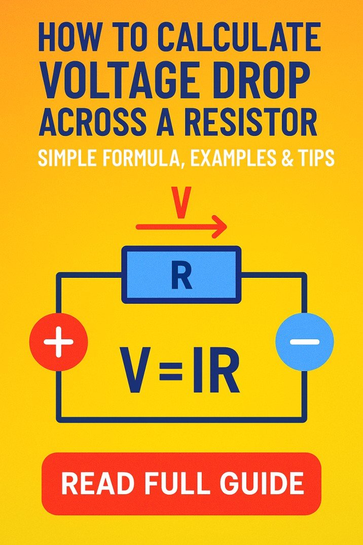
Current-carrying capacity is only one part of cable selection. A long cable run can produce significant voltage drop even when the cable’s thermal capacity is adequate.
Voltage drop depends on factors including:
- Cable length
- Load current
- Conductor resistance
- Conductor material
- Power factor
- Cable configuration
- Supply arrangement
For example, a short 2.5 mm² circuit and a very long 2.5 mm² circuit may carry the same load current, but the longer circuit can experience considerably greater voltage drop.
The installation therefore needs to satisfy both current-carrying and voltage-drop requirements.
Derating Factors and Installation Conditions
Cable ampacity can change substantially depending on how and where the cable is installed.
| Condition | Possible Effect |
|---|---|
| High ambient temperature | Reduces allowable current |
| Multiple loaded cables | Requires grouping correction |
| Thermal insulation | Can reduce heat dissipation |
| Enclosed installation | May reduce capacity |
| Underground installation | Soil conditions become relevant |
| High cable operating temperature | Changes permissible loading |
| Long cable run | Voltage drop becomes more important |
These correction factors are one reason why generic cable charts can produce misleading results when used without checking the installation.
Cable Selection Example With Voltage Drop
Imagine a 230 V load drawing 25 A over a long cable run. A cable may have sufficient thermal capacity for 25 A, but its voltage drop could still become excessive.
The design process should therefore include:
- Determine the design current.
- Identify the installation method.
- Select the appropriate cable construction.
- Apply relevant correction factors.
- Check current-carrying capacity.
- Calculate voltage drop.
- Check short-circuit withstand where applicable.
- Select suitable circuit protection.
- Verify the complete installation against the applicable requirements.
A cable sizing calculator as3008 is useful at the preliminary design stage because it can help compare conductor sizes while considering the main design inputs.
Copper vs Aluminium Cable Sizing
Conductor material also affects cable selection.
Copper has lower electrical resistance than aluminium for the same cross-sectional area. Aluminium conductors can therefore require a larger cross-sectional area to achieve similar electrical performance.
| Feature | Copper | Aluminium |
|---|---|---|
| Electrical conductivity | Higher | Lower |
| Typical conductor size | Smaller | Larger |
| Weight | Higher | Lower |
| Common use | General wiring and feeders | Larger power systems |
| Termination requirements | Standard | Requires appropriate accessories |
The manufacturer’s cable data and applicable installation requirements should always be checked before selecting an aluminium conductor.
Why Cable Protection Matters
The circuit breaker or fuse must be coordinated with the cable and the load. The protective device should not allow the conductor to be subjected to conditions beyond its permitted operating limits.
Cable selection therefore involves more than asking, “What size cable carries this current?”
A proper design considers the relationship between:
Load → Cable → Protective Device → Installation Conditions
If any part of this chain is incorrectly selected, the circuit may not provide the expected level of protection.
For larger projects, it is also useful to compare the result with a detailed cable sizing calculator as3008 calculation before finalizing the cable schedule.
Frequently Asked Questions
What is the AS/NZS 3000 Cable Sizing Table?
The term generally refers to cable size selection information used when designing electrical installations to Australian and New Zealand requirements. AS/NZS 3000 establishes installation rules, while AS/NZS 3008.1.1 provides detailed cable selection information.
What size cable is normally used for a 20 amp circuit in Australia?
A common starting point may be 2.5 mm² copper, but the final size cannot be determined from current alone. Installation method, ambient temperature, grouping, voltage drop, and protective-device requirements must also be checked.
What size cable is required for a 32 amp circuit?
A 6 mm² copper cable is sometimes used for 32 A applications, but it is not a universal rule. The actual allowable current depends on installation conditions and the relevant standard tables.
How do I calculate cable size in Australia?
Start by calculating the design current, then determine the installation method and apply the relevant correction factors. Check current-carrying capacity, voltage drop, fault conditions, and protection before selecting the final conductor size.
Does AS/NZS 3000 cover cable ampacity?
AS/NZS 3000 contains the installation requirements, while detailed cable selection and current-carrying capacity information is provided by AS/NZS 3008.1.1. Both standards may therefore be relevant when designing an installation.
Final Thoughts
Using an AS/NZS 3000 Cable Sizing Table is a useful part of Australian and New Zealand electrical design, but it should not replace a complete cable calculation. The correct conductor depends on design current, installation method, correction factors, voltage drop, protective devices, and the applicable standard.
For simple circuits, a cable chart can provide a quick reference. For commercial, industrial, solar, motor, submain, and long-distance circuits, a more detailed calculation is essential.
Always verify the final cable selection against the current edition of the applicable Australian or New Zealand standards and the manufacturer’s cable data before installation.
Get new guides in your feed. Follow Electrical Insights on LinkedIn for new electrical standards guides, calculators and design tips from Azad Circuit Hub.
#ASNZS3000, #CableSizing, #CableSizingTable, #ElectricalWiring, #ElectricalEngineering, #CableAmpacity, #VoltageDrop, #AustralianStandards, #ElectricalInstallation, #CableSelection