
Standard for Neutral to Earth Voltage: IEC, NEC, BS7671 & IEEE
The iec standard for neutral to earth voltage is a common search query among electricians, electrical engineers, inspectors, and facility maintenance teams. However, an important point is often missed: IEC standards do not generally prescribe one universal neutral-to-earth voltage value that applies to every electrical installation.
The measured voltage between neutral and earth depends on the distribution system, load current, conductor impedance, earthing arrangement, supply transformer, cable length, and the location of the measurement. A small voltage can be normal, while an unusually high reading may indicate a wiring, neutral, earthing, or bonding problem.
| Quick Question | Practical Answer |
|---|---|
| Ideal neutral-to-earth voltage | As close to 0 V as practical |
| Is exactly 0 V always required? | No |
| Typical low-voltage reading | Often 0–2 V under normal conditions |
| Higher reading requiring investigation | Commonly above 2–5 V, depending on installation |
| Dangerous condition | A high or unstable N-E voltage can indicate a fault |
| IEC universal N-E limit | No single universal value is specified |
| Common IEC touch-voltage limit | 50 V AC in ordinary conditions |
| Measurement | Measure AC voltage directly between neutral and PE/earth |
Table of Contents
Table of Contents
What Is Neutral to Earth Voltage?
Neutral to earth voltage is the AC potential difference measured between the neutral conductor and the protective earth (PE) or grounding conductor.
In a properly designed low-voltage system, neutral is normally connected to earth at a defined point according to the distribution arrangement. Because the neutral conductor carries load current, it develops a voltage drop along its length. Therefore, the neutral at a downstream socket may not be exactly at earth potential.
The basic relationship is:
Neutral-to-earth voltage = voltage drop on the neutral path + effects from the earthing and bonding system
For example, if a load draws 20 A through a neutral conductor with 0.05 Ω impedance:
V = I × R
V = 20 × 0.05 = 1 V
The downstream neutral can therefore be approximately 1 V above the local protective earth, even though the system is operating normally.
Is There a Universal IEC Limit?
There is no single IEC rule stating that every installation must have, for example, exactly 0 V, 1 V, or 2 V between neutral and earth.
IEC 60364 focuses on protective measures, automatic disconnection, protective conductors, earthing arrangements, equipotential bonding, insulation, fault protection, and permissible touch voltages. The exact requirements depend on whether the installation uses a TN, TT, or IT system and on the applicable national implementation.
| System | Neutral/Earth Arrangement | Effect on N-E Measurement |
|---|---|---|
| TN-S | Neutral and PE separated downstream | Small voltage can occur because of neutral voltage drop |
| TN-C | Combined PEN conductor | N-E relationship depends on the PEN arrangement |
| TN-C-S | PEN separates into N and PE | Bonding point is important |
| TT | Local earth electrode separate from supply neutral | N-E voltage can behave differently |
| IT | Supply has no direct intentional connection to earth or uses impedance | Normal measurements differ substantially |
Therefore, the correct interpretation of the iec standard for neutral to earth voltage must always consider the earthing system rather than relying on one universal meter reading.
Neutral to Earth Voltage Range
Many electricians use practical voltage ranges as a troubleshooting guide. These values should not be confused with mandatory IEC limits.
| Measured N-E Voltage | General Interpretation |
|---|---|
| 0–1 V | Usually excellent |
| 1–2 V | Common under load |
| 2–5 V | Investigate if persistent or unexpected |
| 5–10 V | Requires detailed checking |
| Above 10 V | Potentially serious wiring, neutral, or earthing issue |
| Fluctuating/high voltage | Investigate urgently |
The actual acceptable value depends on the installation design and measurement conditions.
A voltage reading should always be evaluated together with load current, conductor size, neutral connections, earth impedance, and system type.
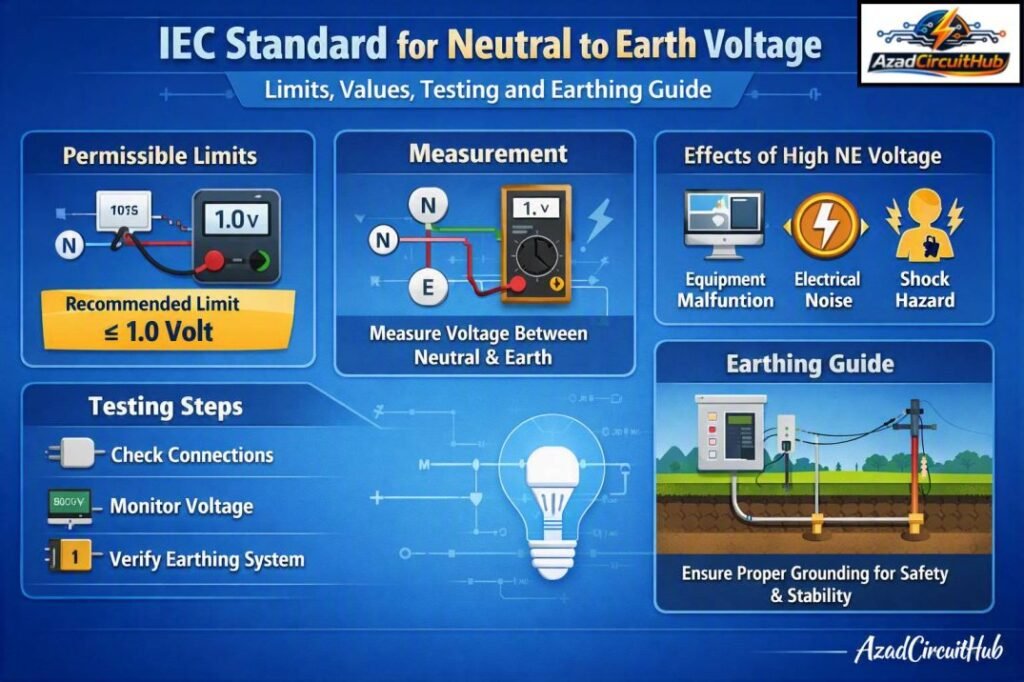
Earth to Neutral Voltage Limit
An earth to neutral voltage limit should not be confused with the IEC permissible touch-voltage requirements.
For protection against electric shock, IEC 60364 uses requirements based on protective measures and automatic disconnection. In ordinary AC installations, 50 V AC is commonly used as the conventional touch-voltage limit under normal conditions.
That does not mean that 50 V between neutral and earth is an acceptable operating N-E voltage. A neutral-to-earth reading approaching such a level can be a serious indication of a fault.
Verify Neutral-to-Earth Voltage with the Fluke 87V
When troubleshooting neutral-to-earth voltage, a reliable meter helps you distinguish normal readings from potential wiring or grounding problems. The Fluke 87V is built for demanding electrical troubleshooting and provides the measurement capability electricians need for voltage, continuity, resistance, and other diagnostic checks. Check the Fluke 87V on Amazon and see the latest price and availability.
NEC Standard for Neutral to Earth Voltage
The NEC does not prescribe one universal maximum Standard for Neutral to Earth Voltage for every installation. Instead, NEC requirements focus on effective grounding, grounded conductor connections, bonding, and minimizing objectionable current. Under NEC 250.24(A)(5), load-side grounded conductors generally must not be reconnected to equipment grounding conductors, while NEC 250.6 addresses objectionable current on grounding paths.
| NEC Reference | Requirement / Guidance | Practical Target |
|---|---|---|
| NEC 250.6 | Avoid objectionable current on grounding paths | Minimize N-E voltage |
| NEC 250.24(A)(5) | No downstream neutral-to-ground connection in typical systems | N-E ≈ 0 V at service bond |
| NEC 250.142(B) | Neutral-to-ground bonding restrictions on load side | Avoid unintended bonding |
| NEC 250.4(A) | Grounding and bonding requirements | Stable reference to earth |
In a properly wired 120/240 V system, a small neutral-to-ground voltage can occur because of voltage drop along the neutral conductor. A reading around 0–2 V under normal load is commonly encountered, while higher values should prompt checks for excessive neutral impedance, loose connections, overloaded conductors, or improper bonding.
The exact acceptable value depends on the installation and operating conditions; the NEC itself should not be interpreted as establishing a blanket 2 V or 5 V limit.
Add a Non-Contact Tester for Quick Safety Checks
A multimeter is useful for confirming measured voltage, but a non-contact tester can provide a quick preliminary indication before you begin detailed testing. If you regularly work on distribution boards, outlets, or control panels, explore our guide to the best non contact voltage tester to compare practical options for everyday electrical work.
IEEE Standard for Neutral to Earth Voltage
IEEE does not prescribe one universal maximum neutral-to-earth voltage for every low-voltage installation. Instead, IEEE standards address grounding, bonding, power quality, and voltage disturbances that help determine whether measured neutral-to-earth voltage is acceptable.
For the Standard for Neutral to Earth Voltage, a practical assessment should therefore consider the system design, load current, grounding impedance, and applicable local code.
| IEEE Reference | Relevant Topic | Practical Guidance |
|---|---|---|
| IEEE Std 142 (Green Book) | Grounding of industrial and commercial power systems | Minimizes objectionable voltage and grounding problems |
| IEEE Std 1100 (Emerald Book) | Power and grounding-sensitive equipment | Addresses grounding and power-quality concerns |
| IEEE Std 3003.1 | Grounding and bonding | Provides guidance for industrial/commercial systems |
| IEEE Std 519 | Harmonic control | Useful where neutral voltage is affected by triplen harmonics |
In a properly bonded system, a small neutral-to-earth voltage can occur because of voltage drop along the neutral conductor. A commonly used field target is 0–2 V, while readings approaching 2–5 V should prompt investigation rather than being treated as an automatic IEEE violation.
Check neutral loading, loose connections, shared neutrals, grounding/bonding points, and harmonic currents before judging the measurement. IEEE guidance should be applied together with NEC, IEC, or BS 7671 requirements applicable to the installation.
BS 7671 Standard for Neutral to Earth Voltage
BS 7671 does not specify a single fixed Standard for Neutral to Earth Voltage limit in volts. Instead, it addresses the underlying causes through requirements for protective conductors, earthing, bonding, fault protection, and automatic disconnection of supply.
In a correctly installed TN or TT system, neutral-to-earth voltage should normally remain low under load, with the actual value affected by neutral current and conductor impedance. Read our complete guide on Neutral to Earth Voltage as per BS7671 UK Regulations here.
| BS 7671 consideration | Relevant requirement | Practical interpretation |
|---|---|---|
| Protective conductor | BS 7671 Section 543 | Must have adequate size and continuity |
| Main bonding | Section 544 | Limits dangerous potential differences |
| Automatic disconnection | Regulation 411 | Fault protection must disconnect within required times |
| TN systems | Regulation 411.4 | Earth fault loop impedance is critical |
| TT systems | Regulation 411.5 | RCD protection is generally required |
| Neutral conductor | Section 524 | Must be suitably sized for expected current |
Typical Neutral-to-Earth Voltage
| Measured N-E voltage | Typical interpretation |
|---|---|
| 0–1 V | Generally low and desirable |
| 1–2 V | Usually acceptable under normal load, investigate if unexpected |
| 2–5 V | Elevated; check neutral loading and connections |
| >5 V | Requires investigation, particularly on sensitive equipment |
These practical measurement ranges are not BS 7671 statutory voltage limits. For compliance, assess the installation against the applicable BS 7671 earthing, bonding, fault-protection and disconnection requirements rather than treating a particular N-E voltage as a pass/fail threshold.
Choose the Right Multimeter for Electrical Testing
Accurate voltage measurements are essential when checking neutral and earth relationships against applicable IEC, NEC, or BS 7671 requirements. If you are comparing professional test instruments, our guide to the best multimeter for electricians can help you evaluate features such as accuracy, safety ratings, durability, and troubleshooting functions before buying.
Neutral to Earth Voltage Standard in India
The neutral to earth voltage standard in India needs to be considered through the applicable Indian Standards, electricity regulations, and the electrical installation design.
IS 732 covers electrical wiring installations and incorporates principles associated with protection against electric shock. IS 3043 provides guidance on earthing practices.
There is not a simple Indian rule that says every socket must measure one fixed neutral-to-earth voltage.
| Reference | Main Relevance |
|---|---|
| IS 732 | Electrical wiring installations |
| IS 3043 | Code of practice for earthing |
| IEC 60364 | Low-voltage electrical installations |
| CEA safety regulations | Electrical safety requirements in India |
| Local supply utility requirements | Service and distribution conditions |
Thus, neutral to earth voltage as per Indian standard should be assessed according to the complete installation and applicable requirements rather than a single numerical N-E target.
Neutral to Earth Voltage in Single Phase Systems
In a typical single-phase supply, the phase conductor supplies the load and the neutral conductor returns current to the source.
When current flows through the neutral conductor, its resistance produces voltage drop. This creates a measurable earth to neutral voltage in single phase circuits.
For example:
| Condition | Typical Result |
|---|---|
| No load | Very low N-E voltage |
| Small load | Small increase |
| Heavy load | Greater neutral voltage drop |
| Long neutral conductor | Greater voltage drop |
| Loose neutral connection | Potentially high or unstable voltage |
| Shared or overloaded neutral | Increased voltage drop |
A small increase in N-E voltage when a large load starts is not automatically a fault.
What Should Be the Voltage Between Neutral and Earth?
For a properly functioning low-voltage installation, the practical goal is to keep the neutral-to-earth voltage as low as reasonably achievable.
A reading close to 0 V is desirable, but a small voltage caused by normal neutral conductor voltage drop can occur.
The question “what should be neutral to earth voltage?” therefore cannot be answered with one number for every electrical system.
A useful practical target is:
Lower is generally better, provided the earthing and bonding arrangement complies with the applicable standard.
Why Neutral to Earth Voltage Is High
A high N-E voltage can have several causes. Finding the actual cause is more important than simply trying to reduce the meter reading.
Common causes include:
- High neutral conductor resistance
- Loose neutral terminals
- Damaged or undersized neutral conductors
- Excessive load current
- Poor connections at distribution boards
- Open or compromised neutral conductors
- Incorrect neutral-earth bonding
- Shared neutral problems
- High impedance in the supply network
- Poor or damaged protective earthing
- Incorrect PEN conductor arrangements
- Voltage drop over long cable runs
A loose neutral deserves particular attention because it can create unstable voltages and potentially damage connected equipment.
How to Reduce Neutral to Earth Voltage
The correct method is to identify and eliminate the cause rather than simply adding another earth connection.
| Problem | Corrective Approach |
|---|---|
| High neutral voltage drop | Check conductor size and circuit loading |
| Loose neutral | Isolate supply and inspect/retighten correctly |
| Poor termination | Inspect and remake termination |
| Excessive circuit length | Review cable sizing and distribution |
| Incorrect bonding | Correct bonding according to system design |
| High earth impedance | Test and improve the earthing system where required |
| Overloaded neutral | Review load distribution |
| Damaged PEN/neutral | Repair under qualified supervision |
Never create an additional neutral-to-earth link simply because the measured voltage is high. An unauthorized bond can cause current to flow on protective conductors and metallic equipment parts.
Neutral to Earth Resistance Value
A voltage test and a resistance test are different measurements.
A multimeter can measure the voltage between neutral and earth, but it does not establish whether an earth electrode complies with the required earthing resistance.
For an earthing system, the required resistance depends on the installation type and protection method. In a TT system, for example, the relationship between earth electrode resistance, protective-device operation, and permissible touch voltage is important.
The commonly used relationship is:
RA × IΔn ≤ 50 V
where RA is the earth electrode and protective conductor resistance and IΔn is the rated residual operating current of the RCD.
The actual design must follow the applicable standard and protective-device characteristics.
IEC Standard for Earthing
The iec standard for earthing is not limited to achieving a low resistance number. IEC 60364 considers the complete protective system, including protective conductors, automatic disconnection, equipotential bonding, earthing arrangements, and fault-loop conditions.
| Earthing System | Key Protection Principle |
|---|---|
| TN | Fault current generally returns through a metallic protective path |
| TT | Local earth electrode is used with appropriate protective devices |
| IT | Supply is isolated from earth or connected through impedance |
This distinction is essential when interpreting neutral and earth voltage.
Ground to Neutral Voltage Standard
The terms ground and earth are often used interchangeably in general electrical discussions, although terminology varies by country and application.
There is no universal ground to neutral voltage standard that requires one identical meter reading for every system.
In a correctly installed TN-S system, the PE conductor should not normally carry normal load current. The neutral conductor does carry load current, so voltage drop along the neutral creates a measurable difference between N and PE.
Earth and Neutral Voltage Testing
Before performing an earth-to-neutral voltage check, identify the supply arrangement and use an appropriate CAT-rated meter.
A basic procedure is:
- Verify the test instrument is rated for the installation.
- Inspect the socket or distribution board visually.
- Measure phase-to-neutral voltage.
- Measure phase-to-earth voltage.
- Measure neutral-to-earth voltage.
- Repeat measurements under different load conditions.
- Compare results with the installation design.
- Investigate abnormal or unstable readings.
| Test | What It Indicates |
|---|---|
| Phase–Neutral | Supply voltage to the load |
| Phase–Earth | Supply voltage relative to protective earth |
| Neutral–Earth | Neutral voltage rise relative to PE |
| Earth electrode resistance | Effectiveness/impedance of the earthing arrangement |
Do not deliberately short neutral and earth together during testing.
30kVA Transformer and Neutral-Earth Voltage
A 30kVA transformer can supply substantial current depending on its secondary voltage. For a three-phase 400 V secondary:
I = 30,000 ÷ (√3 × 400)
This gives approximately 43.3 A per phase at full load, assuming unity power factor.
For a single-phase 230 V secondary, the corresponding full-load current is approximately 130 A.
The transformer size itself does not establish a fixed neutral-to-earth voltage. Transformer winding configuration, neutral grounding, conductor impedance, loading, and downstream bonding all affect the measurement.
Ideal Earthing Voltage
The phrase ideal earthing voltage can be misleading. Earth is used as a reference and protective path, but an earth electrode is not automatically at exactly 0 V under every fault or operating condition.
During an earth fault, current flowing through an earthing electrode can produce a voltage rise. This is why protection against electric shock considers touch voltage, fault current, disconnection time, and equipotential bonding.
Neutral or Earth: What Is the Difference?
Neutral and earth are not interchangeable conductors.
| Neutral | Protective Earth |
|---|---|
| Normally carries load current | Normally carries no load current |
| Part of the normal circuit | Protective conductor |
| Connected to source neutral point | Connected to exposed conductive parts |
| Voltage drop occurs under load | Should remain close to the local reference potential |
| Used for circuit return | Used for fault protection |
Incorrectly treating the earth conductor as a neutral can create a serious electrical safety hazard.
Acceptable Voltage Between Neutral and Earth
An acceptable voltage between neutral and earth is installation-dependent. A low reading is normally desirable, but the reading alone does not prove that an electrical installation is safe.
For example, a circuit showing 1.5 V N-E may be operating normally, while another installation showing the same reading could have a developing connection problem if the value suddenly increased from a previously stable level.
Trend and load-dependent measurements are therefore useful during troubleshooting. Read our complete guide on Neutral to Earth Voltage Acceptable Limits here.
Neutral Earthing Voltage and Bonding
Neutral-earth bonding must occur at the location permitted by the particular earthing system. In a TN-C-S arrangement, for example, the PEN conductor is separated into neutral and protective conductors at the designated point.
After separation, downstream neutral and PE conductors should not be casually bonded together.
Incorrect bonding can cause neutral current to flow through protective conductors, cable screens, metal conduit, building steelwork, or other conductive paths.
Neutral to Ground Voltage Limit
There is no universal neutral to ground voltage limit applicable to every installation.
For practical troubleshooting, electricians often regard a few volts as a reason to investigate, especially when the voltage increases significantly with load or fluctuates unexpectedly. However, these practical thresholds are diagnostic guidelines, not universal IEC compliance limits.
The actual safety assessment should be based on the applicable installation standard and protective-disconnection requirements. For complete understanding read our guide on Neutral to Ground Voltage
Normal Neutral to Earth Voltage
A normal neutral to earth voltage is generally low and stable.
A reading can increase as load current increases because the neutral conductor develops voltage drop. If the reading becomes unusually high, changes sharply, or differs substantially between circuits, further testing is appropriate.
Particular attention should be given to a high reading accompanied by flickering lights, equipment malfunction, overheating terminals, or unexplained voltage changes.
Frequently Asked Questions
What should be the voltage between neutral and earth?
Ideally, the voltage should be close to 0 V, but a small reading is common because the neutral conductor has impedance and carries load current. There is no universal IEC value that applies to every installation.
Is 5V between neutral and earth acceptable?
A 5 V reading should not automatically be classified as safe or unsafe. It should be checked against the system design, load current, cable length, and earthing arrangement. If the reading is persistent or has recently increased, investigate the cause.
Why is neutral to earth voltage high?
High N-E voltage can result from neutral voltage drop, overloaded conductors, loose connections, damaged neutrals, incorrect bonding, poor earthing, or problems with the supply network. A qualified electrician should investigate abnormal readings.
How do you reduce neutral to earth voltage?
First identify the cause. Check neutral connections, conductor sizing, circuit loading, voltage drop, earthing, and bonding. Do not install an unauthorized neutral-earth link to force the meter reading toward zero.
What does IEC say about neutral to earth voltage?
IEC installation standards do not provide one universal numerical N-E voltage limit for all low-voltage systems. IEC 60364 instead addresses earthing arrangements, protective conductors, equipotential bonding, automatic disconnection, and protection against electric shock.
Key Takeaways
The iec standard for neutral to earth voltage should be understood as part of the complete electrical installation rather than as a single acceptable meter value.
The most important points are:
- A small N-E voltage can be normal.
- Neutral voltage rises because the neutral conductor carries current and has impedance.
- Exactly 0 V is desirable but not always achievable in practical installations.
- IEC does not prescribe one universal N-E voltage limit for every system.
- TN, TT, and IT systems must be assessed differently.
- A high or unstable N-E reading requires investigation.
- Neutral and protective earth conductors must not be bonded arbitrarily.
- Earth electrode resistance is a different measurement from N-E voltage.
- Indian installations should also be assessed against applicable IS, CEA, and utility requirements.
- Electrical safety should be based on the complete protective system, not one multimeter reading.
When troubleshooting, always identify the earthing arrangement first. Then evaluate neutral voltage drop, protective-conductor continuity, bonding, earth impedance, fault protection, and automatic disconnection requirements against the standard applicable to the installation.
Get new guides in your feed. Follow Electrical Insights on LinkedIn for new electrical standards guides, calculators and design tips from Azad Circuit Hub.
#NeutralToEarthVoltage, #VoltageStandard, #IECStandards, #NEC, #BS7671, #IEEE, #ElectricalSafety, #EarthVoltage, #ElectricalTesting, #PowerSystems
