
Neutral to Earth Voltage as per BS7671 UK Regulations
For electricians working on UK electrical installations, checking the voltage between neutral and earth is a useful diagnostic test. A small reading can be normal, especially when a circuit is carrying load. A higher or unstable reading can point to voltage drop, a poor neutral connection, wiring problems, or an issue with the earthing arrangement.
It is important to understand that BS 7671 does not prescribe one simple fixed value as the maximum allowable neutral-to-earth voltage for every installation. Instead, the regulations deal with protection against electric shock, automatic disconnection, touch voltage, earthing arrangements, conductor sizing, and voltage drop.
This distinction is important when interpreting measurements in domestic, commercial, and industrial installations.
Quick Reference: Neutral to Earth Voltage in UK Installations
| Measurement or requirement | Typical interpretation |
|---|---|
| Neutral to earth close to 0 V | Generally expected with little load |
| 0–2 V N-E | Often normal in many installations |
| 2–5 V N-E | May occur because of neutral voltage drop |
| Above 5 V N-E | Requires further investigation |
| Around 50 V AC | Significant shock hazard if accessible |
| BS 7671 approach | No universal fixed N-E voltage limit |
| Main concern | Shock protection, voltage drop and installation condition |
| Relevant earthing systems | TN-S, TN-C-S and TT |
These values are practical diagnostic ranges rather than limits prescribed by BS 7671. The actual reading depends on the installation, circuit length, load current, supply arrangement and measurement point.
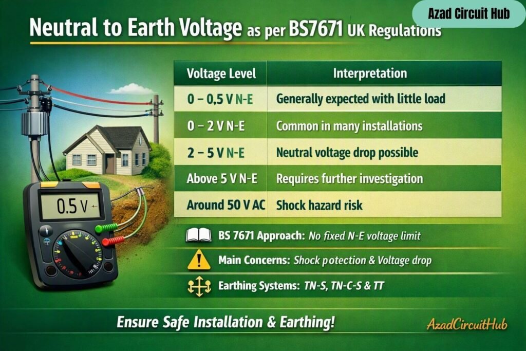
Table of Contents
Table of Contents
What Is Neutral to Earth Voltage?
Neutral to earth voltage is the potential difference measured between the neutral conductor and the protective conductor or earth.
In a correctly operating installation, neutral and earth are normally at nearly the same potential at the relevant supply reference point. However, they are not interchangeable conductors.
The neutral carries normal operating current. The protective conductor normally carries no continuous load current and provides a low-impedance path for fault current.
When current flows through the resistance or impedance of a neutral conductor, a voltage develops along that conductor. This means the neutral at a socket or distribution board can be several volts above the local earth potential.
This is why a voltage reading does not automatically indicate a fault.
Is Neutral to Earth Voltage Specified by BS 7671?
The phrase Neutral to Earth Voltage as per BS7671 can be misleading because BS 7671 does not provide a general rule stating that neutral-to-earth voltage must always be exactly 0 V.
Instead, BS 7671 establishes requirements for protective measures against electric shock and automatic disconnection of supply. The design must ensure that exposed-conductive-parts do not remain at dangerous voltages for unacceptable periods during a fault.
Regulations in Part 4, particularly those concerning protection against electric shock and automatic disconnection, are therefore more important than treating a particular N-E meter reading as a standalone pass/fail test.
| BS 7671 area | Why it matters |
|---|---|
| Section 411 | Protection against electric shock by automatic disconnection |
| Regulation 411.3.2 | Automatic disconnection of supply |
| Regulation 411.3.2.2 | Requirements relating to fault protection and touch voltage |
| Chapter 43 | Protection against overcurrent |
| Chapter 52 | Selection and erection of wiring systems |
| Chapter 54 | Earthing arrangements and protective conductors |
| Chapter 64 | Initial verification and inspection/testing |
For a wider explanation of acceptable readings and testing principles, see our guide to neutral to earth voltage standard and how different standards approach the measurement.
Why Does Neutral to Earth Voltage Increase Under Load?
A neutral conductor has resistance. When current flows through it, the voltage drop can be calculated approximately using:
V = I × R
Where:
- V = voltage drop
- I = current flowing through the neutral
- R = resistance of the neutral conductor
For example, if a neutral conductor has a total resistance of 0.15 Ω and carries 20 A:
V = 20 × 0.15 = 3 V
A meter could therefore show approximately 3 V between neutral and earth at that point.
| Load current | Neutral resistance | Approximate neutral voltage rise |
|---|---|---|
| 5 A | 0.10 Ω | 0.5 V |
| 10 A | 0.10 Ω | 1.0 V |
| 20 A | 0.10 Ω | 2.0 V |
| 30 A | 0.10 Ω | 3.0 V |
| 40 A | 0.10 Ω | 4.0 V |
The actual value depends on conductor length, temperature, conductor size, connections and the complete circuit impedance.
Neutral to Earth Voltage on TN-S, TN-C-S and TT Systems
The earthing arrangement has a major influence on measurements.
In a TN-S system, the protective earth and neutral are separate conductors throughout the installation, although they have a common reference at the supply source.
In a TN-C-S system, the supply uses a combined protective and neutral conductor upstream, with separation into PE and N at the installation’s connection point. The arrangement creates specific requirements for protective bonding and fault protection.
A TT system uses a local earth electrode for the installation. Its earth reference can therefore behave differently from the supply neutral.
| Earthing system | Neutral and earth arrangement | Typical diagnostic consideration |
|---|---|---|
| TN-S | Separate N and PE from supply | Neutral voltage drop is often measurable under load |
| TN-C-S | PEN upstream, separated into N and PE | PME and bonding requirements are important |
| TT | Local earth electrode | Earth electrode resistance and RCD protection are important |
If you are measuring the voltage between earth and neutral, always identify the earthing system before deciding whether the result is unusual.
How to Measure Neutral to Earth Voltage Safely
A voltage measurement should be performed with a correctly rated test instrument and suitable test leads. The measurement itself does not prove that an installation is safe.
At a suitable testing point, measure:
Neutral (N) → Protective Earth (PE)
Then compare the result with other measurements, such as:
- Line to neutral
- Line to earth
- Neutral to earth
- Supply voltage under load
- Voltage drop at the circuit
- Earth fault loop impedance where applicable
A useful diagnostic method is to measure the N-E voltage with the circuit unloaded and then repeat the measurement while a known load operates.
| Test condition | Interpretation |
|---|---|
| Low N-E unloaded and low under load | Usually normal |
| Low unloaded, higher under load | Possible neutral voltage drop |
| High N-E with little load | Investigate connections or supply |
| Unstable N-E reading | Check neutral connections and supply |
| Different readings at several boards | Investigate circuit voltage drop and connections |
Never use a high N-E reading alone to diagnose the fault. It should be considered alongside the complete test results.
Common Causes of High Neutral to Earth Voltage
A higher-than-expected reading can have several causes.
| Possible cause | Typical indication |
|---|---|
| Excessive neutral voltage drop | Reading increases with load |
| Loose neutral connection | Fluctuating or abnormal voltage |
| Undersized neutral conductor | Higher voltage drop |
| Long circuit length | Greater voltage drop |
| Poor termination | Localised heating or unstable readings |
| Supply-side neutral issue | Abnormal readings across multiple circuits |
| Parallel neutral paths | Unexpected current or voltage |
| Incorrect wiring | Potentially dangerous condition |
A loose neutral deserves particular attention. High-resistance connections can heat under load and may become progressively worse.
Neutral to Earth Voltage and Voltage Drop
Voltage drop is directly relevant when investigating an elevated N-E measurement. BS 7671 contains requirements for designing circuits so that voltage drop remains within appropriate limits for the installation and equipment.
The N-E measurement can sometimes reveal where the neutral is losing voltage relative to the protective conductor.
For example, a long final circuit supplying a substantial load can develop measurable neutral voltage rise. This does not necessarily mean the earth conductor is faulty.
For larger installations, the relationship between conductor size, current, impedance and protective device operation should be assessed rather than relying on a single voltage reading.
Neutral to Earth Voltage in Consumer Units and Distribution Boards
At a UK consumer unit or distribution board, neutral-to-earth measurements can be useful during fault finding.
A low reading with normal load is generally expected. If the voltage increases significantly when a large load is switched on, investigate neutral conductor impedance and terminations.
Where several circuits show an unusual reading, the problem may be upstream rather than confined to one final circuit.
For broader guidance on earth to neutral voltage, including practical measurement considerations, compare readings at the origin, distribution board and final circuit where safe and appropriate.
Relationship Between Neutral Voltage and Protective Earth
Neutral and protective earth perform different functions even when their potentials are close.
| Conductor | Normal function | Carries normal load current? |
|---|---|---|
| Line | Supplies power to loads | Yes |
| Neutral | Returns current to source | Yes |
| Protective conductor | Provides fault-current path | Normally no |
| Main bonding conductor | Connects extraneous-conductive-parts to earthing system | Normally no |
Connecting neutral and earth together at an incorrect point can create objectionable current on protective conductors and bonding paths. Such connections should not be added simply to reduce a measured voltage.
If cable selection is contributing to voltage drop, use an earth cable size calculator alongside the appropriate conductor sizing method and the requirements of BS 7671.
What Should You Do If Neutral to Earth Voltage Is High?
The correct response depends on the measured value, installation type and test conditions.
Start by recording the voltage with the circuit lightly loaded. Then repeat the measurement under a known load. Check whether the reading changes significantly.
Next, inspect the installation for loose or damaged connections, excessive conductor length, incorrect terminations and other signs of overheating.
For professional verification, carry out the relevant tests required for the installation rather than relying solely on a multimeter reading.
A high or unstable N-E voltage should receive particular attention when accompanied by flickering lights, equipment malfunction, overheating terminals, nuisance tripping or unusual voltage readings.
FAQs About Neutral to Earth Voltage as per BS7671
What is an acceptable neutral to earth voltage in the UK?
There is no single universal N-E voltage limit specified by BS 7671 for every installation. A low reading is normally expected, while a few volts can occur because of neutral voltage drop under load. Higher or unstable readings should be investigated.
Should neutral and earth have the same voltage?
They should normally be close in potential at the relevant reference point, but they are separate conductors with different functions. A measurable voltage can develop because current flowing through the neutral causes voltage drop.
Is 5 volts between neutral and earth safe?
A 5 V reading does not by itself establish whether an installation is safe or compliant. It should be assessed in relation to load current, circuit impedance, earthing arrangement and the wider BS 7671 test results.
Why do I get voltage between neutral and earth?
The most common reason is voltage drop along the neutral conductor caused by load current. Other causes include poor connections, wiring problems, supply issues and unwanted neutral-earth connections.
What causes high neutral to earth voltage?
Possible causes include excessive neutral impedance, long circuits, undersized conductors, loose terminals, supply-side neutral problems and incorrect wiring. The reading should be investigated alongside other electrical test results.
Final Thoughts
Understanding Neutral to Earth Voltage as per BS7671 requires more than looking for a single number on a multimeter. BS 7671 focuses on the overall safety of the installation, including protective measures, automatic disconnection, earthing, bonding, conductor selection and verification.
A small N-E voltage can be a normal result of load current and conductor impedance. A high, unstable or load-sensitive reading deserves further investigation, particularly when other symptoms are present.
For a wider comparison of acceptable measurements, standards and practical testing methods, see our detailed guide covering voltage between earth and neutral and related UK electrical requirements.
Get new guides in your feed. Follow Electrical Insights on LinkedIn for new electrical standards guides, calculators and design tips from Azad Circuit Hub.
#NeutralToEarthVoltage, #BS7671, #UKElectricalRegulations, #ElectricalTesting, #EarthVoltage, #NeutralVoltage, #ElectricalSafety, #ElectricalWiring, #ElectriciansUK, #BS7671Regulations
