
Neutral to Earth Voltage Acceptable Limits (IEC): Best Guide
Neutral-to-earth voltage is a useful field measurement when troubleshooting electrical systems. A small voltage between neutral and protective earth can appear because current flows through the neutral conductor and creates a voltage drop. The reading can also point to loose connections, poor earthing, overloaded circuits, or neutral conductor problems.
When checking Neutral to Earth Voltage Acceptable Limits, it is important to understand that IEC standards do not simply specify one universal value that every installation must meet. The acceptable reading depends on the system arrangement, load current, neutral conductor impedance, earthing system, and the point where the measurement is taken.
Neutral to Earth Voltage Acceptable Limits Quick Table
| Measurement | Typical field observation | What it may indicate |
|---|---|---|
| Neutral to earth | 0–2 V | Usually low and commonly observed |
| Neutral to earth | 2–5 V | Investigate load and voltage drop |
| Neutral to earth | Above 5 V | Requires further testing |
| Neutral to earth | High or unstable | Possible wiring, neutral, or earthing fault |
| Neutral-earth near source | Very low | Expected when connections are sound |
These values are practical troubleshooting guidelines, not universal IEC limits.
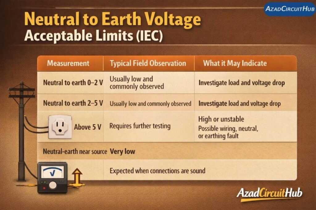
Table of Contents
Table of Contents
What Is Neutral to Earth Voltage?
Neutral-to-earth voltage is the potential difference measured between the neutral conductor and the protective earth conductor. A digital multimeter can normally measure it by placing one probe on neutral and the other on earth.
Ideally, neutral and earth remain at nearly the same potential at the main supply point where the system bonding arrangement is established. However, neutral carries normal load current, while the protective earth conductor should not normally carry continuous load current.
Because the neutral conductor has resistance and impedance, load current produces a voltage drop along its length. This is why a small neutral-to-earth reading can be present at a distribution board or final circuit.
For a broader explanation of the terminology and calculation methods, readers can also review the neutral earth voltage standard guide.
Is There a Fixed IEC Acceptable Limit?
One important point is often missed in online discussions: IEC 60364 does not establish a single universal “neutral-to-earth voltage” limit for every installation.
IEC 60364 focuses on electrical safety, protection against electric shock, protective conductors, automatic disconnection, earthing arrangements, and voltage-drop considerations. The measured N-E voltage therefore has to be interpreted according to the complete installation.
| Situation | Engineering interpretation |
|---|---|
| 0–1 V | Generally indicates very little neutral voltage drop |
| 1–2 V | Common in many loaded installations |
| 2–5 V | Worth investigating, especially on sensitive equipment |
| More than 5 V | Check neutral connections, loading and conductor impedance |
| Fluctuating voltage | Check loose connections, shared neutrals and load changes |
| High voltage with low load | Requires prompt investigation |
These ranges should not be treated as IEC compliance thresholds. The actual safety assessment must consider the installation design and applicable national requirements.
Why Does Neutral to Earth Voltage Increase?
The most common reason is voltage drop in the neutral conductor. If several loads share a neutral, the current flowing through that conductor can increase the voltage difference between neutral and earth.
A simple relationship is:
V = I × Z
where V is voltage drop, I is current, and Z represents conductor impedance.
For example, a neutral conductor carrying 20 A with an impedance of 0.1 ohm would produce approximately 2 V of voltage drop.
Other causes include:
- Loose neutral terminals
- Undersized neutral conductors
- Excessive circuit loading
- Long cable runs
- Shared or incorrectly connected neutrals
- Poor neutral connections
- Incorrect neutral-earth bonding
- Harmonic currents from nonlinear loads
- Earthing system problems
This is why a high reading should not be judged from the multimeter value alone.
Neutral to Earth Voltage Under Load
A useful troubleshooting method is to compare the reading at different load conditions. Measure neutral-to-earth voltage with the circuit lightly loaded, then repeat the test while significant loads are operating.
| Test condition | Reading | Possible interpretation |
|---|---|---|
| No major load | 0.3 V | Low voltage difference |
| Moderate load | 1.2 V | Normal conductor voltage drop may explain it |
| Heavy load | 3.5 V | Investigate neutral impedance |
| Heavy load | 7 V | Detailed fault finding recommended |
| Reading changes sharply | 0.5–8 V | Check neutral connections and load distribution |
A useful comparison is to measure voltage at the main distribution board and then at the downstream circuit. A significant increase along the circuit can help locate the source of neutral voltage drop.
For related terminology and practical measurement guidance, see the earth to neutral voltage standard resource.
How to Measure Neutral to Earth Voltage
Use an appropriately rated true-RMS multimeter for the installation and follow the manufacturer’s safety instructions.
- Select the appropriate AC voltage range.
- Connect the reference probe to protective earth.
- Connect the other probe to neutral.
- Record the voltage with the circuit lightly loaded.
- Repeat the measurement under normal operating load.
- Compare readings at the source and downstream points.
Never assume that an earth conductor is safe simply because a low voltage is measured. A defective protective conductor can create dangerous conditions that are not always obvious from one voltage measurement.
Electricians should also verify neutral continuity, protective conductor continuity, insulation condition, polarity, and the effectiveness of protective devices where required.
Neutral Voltage and Sensitive Equipment
A small N-E voltage may not cause a visible problem with conventional resistive loads. Sensitive electronic equipment can be different.
PLC systems, variable-frequency drives, computers, instrumentation, communication equipment, and control systems can be affected by electrical noise, grounding differences, harmonics, or unstable supply conditions.
For these systems, troubleshooting should include:
- Neutral voltage under different loads
- Protective earth continuity
- Grounding arrangement
- Harmonic distortion
- Voltage imbalance
- Supply voltage stability
- Equipment bonding
The neutral to earth voltage standard guide can also help when comparing field measurements with installation requirements.
Neutral-Earth Voltage and Indian Installations
Engineers working in India should distinguish IEC guidance from Indian regulatory and installation requirements. Indian installations may use standards and codes such as IS 732 and related electricity-safety requirements.
Therefore, searching only for a single number under Neutral to Earth Voltage Acceptable Limits can be misleading. The correct assessment depends on the system design, earthing arrangement, supply characteristics, and applicable Indian requirements.
For readers working specifically with Indian installations, this neutral to earth voltage as per indian standard resource provides a useful starting point.
When Should You Investigate the Reading?
A low N-E voltage is usually less concerning than a high, rising, or unstable reading. The trend is often more useful than one isolated measurement.
Investigate further when:
- The voltage rises significantly with load.
- The reading exceeds several volts.
- Neutral voltage changes suddenly.
- Different circuits show unusual differences.
- Lights fluctuate when large loads start.
- Electronic equipment shows unexplained faults.
- Neutral terminals show signs of heating.
- There is evidence of a loose or shared neutral.
A thermal inspection can also help identify a high-resistance neutral connection. Any suspected loose or damaged connection should be isolated and repaired using appropriate electrical safety procedures.
Frequently Asked Questions
What is an acceptable neutral-to-earth voltage?
There is no single universal IEC value for every installation. A low reading, often around 0–2 V under normal conditions, is commonly observed in sound systems. Higher readings should be investigated in context.
Is 5 volts between neutral and earth safe?
A 5 V reading should not automatically be classified as safe or unsafe. It may result from neutral voltage drop, but the cause should be identified, particularly if the reading increases under load or varies significantly.
Why do I get voltage between neutral and earth?
The most common cause is voltage drop in the neutral conductor. Other possibilities include loose neutral connections, incorrect bonding, shared neutrals, harmonic currents, or earthing problems.
Should neutral and earth have the same voltage?
They should be at nearly the same potential at the appropriate bonding point, but a voltage difference can develop at downstream points because the neutral carries load current and has impedance.
How do I reduce neutral-to-earth voltage?
Check neutral conductor sizing, terminal tightness, circuit loading, shared neutrals, conductor impedance, and the overall earthing arrangement. Do not simply add an additional neutral-earth bond to reduce the measured voltage, because incorrect bonding can create dangerous current paths.
Get new guides in your feed. Follow Electrical Insights on LinkedIn for new electrical standards guides, calculators and design tips from Azad Circuit Hub.
#NeutralToEarthVoltage, #EarthVoltage, #IECStandards, #ElectricalSafety, #NeutralVoltage, #EarthingSystem, #ElectricalTesting, #VoltageMeasurement, #ElectricalEngineering, #ElectricalTroubleshooting
