How to Test a Ring Main Circuit Continuity: 3-Step Guide
If you want to know how to test a ring main circuit continuity, the answer is three measurements: the end-to-end resistance of each ring conductor, a figure of 8 cross-connection reading at every socket, and a polarity check. This guide, written by an electrical engineer, shows each step, the results you should expect, and where a plain multimeter falls short.
This post is a spoke of our Complete Guide to Home Wiring & BS 7671 (UK), so it follows BS 7671 and IET Guidance Note 3 practice. US readers: American homes use radial branch circuits under the NEC, not rings, so see our NEC home wiring guide instead. Everything below applies to UK-style ring final circuits.
Safety first: before you try how to test a ring main circuit continuity, only test circuits you are competent to isolate. Use a two-pole voltage indicator, prove it on a known source before and after, and lock off the supply. If you are unsure, hire a qualified electrician.
What Is a Ring Main Circuit?
A ring main, correctly called a ring final circuit, is a loop of cable that leaves the consumer unit (the UK term for a breaker panel), passes every socket, and returns to the same protective device. Line, neutral and the circuit protective conductor (CPC) all run the full loop. That is why current can reach any socket along two paths, which lets a 2.5 mm² cable serve a 32 A device.
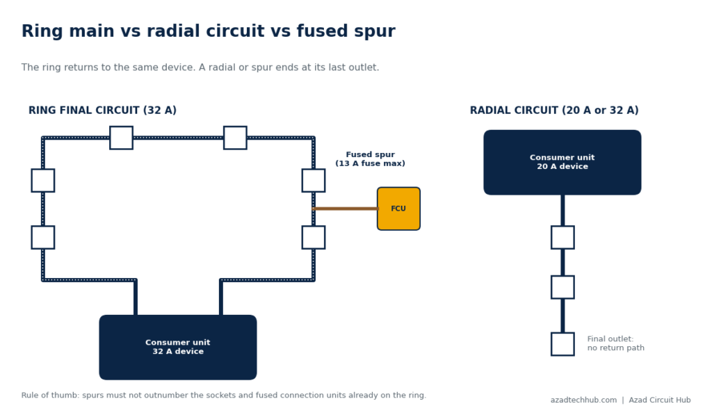
A radial circuit is different. It runs from the consumer unit to the last outlet and stops. There is no return leg, so how to test a ring main circuit continuity does not apply here, only straightforward continuity and the other standard tests. Our hub explains both layouts in the ring final circuits and radial socket circuits section.
Why Ring Continuity Matters
A ring can look healthy while hiding a break. Every socket still works because the other leg feeds it, but now the cable is carrying current as a radial. Under heavy load that cable can overheat while the 32 A device sees nothing wrong. Knowing how to test a ring main circuit continuity catches this before it becomes a fire risk, and it is part of every new installation, rewire and EICR.
Tools You Need
Different jobs need different kit, and the right purchase saves real time when you practise how to test a ring main circuit continuity regularly:
- Low-resistance ohmmeter or multifunction installation tester (MFT): needed for certificate-grade readings. Compare options in our Panel Testers & Circuit Analyzers reviews.
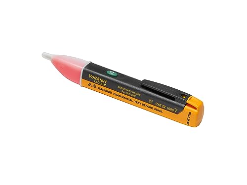
- Two-pole voltage indicator with proving unit: for safe isolation. A non-contact tester is not enough. See our voltage tester reviews.
- Digital multimeter: useful for finding breaks and identifying conductors. Browse the multimeter reviews.
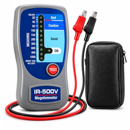
- Insulation resistance tester: the next test after continuity. Our best insulation resistance testers buyer’s guide cover this.
- Short test links and a socket tester: to cross-connect conductors and check polarity.



How to Test a Ring Main Circuit Continuity With Multimeter
Can you do it with a multimeter? Partly. A basic multimeter can tell you whether a conductor is broken, and it can help you find which cable ends belong together. What it cannot do is prove compliance. Most multimeters resolve only 0.1 Ω and push far less than the 200 mA test current that BS 7671 expects for continuity testing. The figure of 8 readings are around 0.2 to 0.3 Ω, which a typical multimeter simply cannot display accurately.
So the practical rule for how to test a ring main circuit continuity with multimeter is this: use it to check for open circuits and to identify cable pairs, then confirm the actual values with a low-resistance ohmmeter or MFT. If you only own a multimeter, you can still do a useful check before calling an electrician, but do not issue a certificate on it.
How to Test a Ring Main Circuit Continuity Using a Low-Resistance Ohmmeter
When you learn how to test a ring main circuit continuity using a proper low-resistance ohmmeter, you need an instrument that injects at least 200 mA and shows readings to 0.01 Ω. Zero the leads first (null the lead resistance), then follow the steps below. Check the instrument’s calibration date as well, because a drifting tester gives confident but wrong numbers.
Ring Continuity Test Steps
This is how to test a ring main circuit continuity in the correct order. Each step builds on the one before.
Step 0: Isolate and prepare. Preparation is the most important part of how to test a ring main circuit continuity safely. Switch off, lock off and prove dead. Remove the ring conductors from the consumer unit terminals and separate them so no conductor touches another. Identify the two cables (the two legs) that make up the ring.
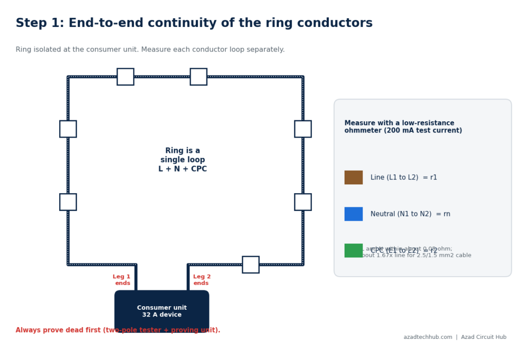
Step 1: End-to-End Continuity (r1, rn, r2)
Measure the resistance between the two ends of each conductor loop: line to line (r1), neutral to neutral (rn) and CPC to CPC (r2). Record all three values.
- r1 and rn should be about equal, within roughly 0.05 Ω.
- For a standard 2.5 mm² line and neutral with a 1.5 mm² CPC, r2 should be about 1.6 to 1.7 times r1.
- If any reading is open circuit, the ring is broken somewhere.
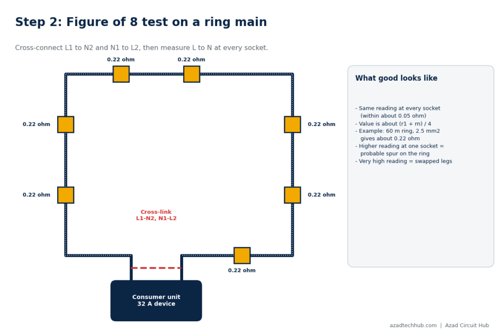
Step 2: Figure of 8 Test Ring Main (Line and Neutral)
This is the part most people mean by the figure of 8 test ring main method. Cross-connect the ends: join line of leg 1 to neutral of leg 2, and neutral of leg 1 to line of leg 2. Then measure between line and neutral at every socket on the ring.
The readings should all be substantially the same, within about 0.05 Ω, and roughly equal to (r1 + rn) divided by 4. A higher reading at one socket points to a spur or a poor joint. A very high reading across the whole ring suggests crossed legs.
Step 3: Line and CPC Cross-Connection (R1 + R2)
The last part of how to test a ring main circuit continuity checks the earth path. Cross-connect line of leg 1 to the CPC of leg 2, and the reverse. Measure between line and earth at every socket. The values rise towards the middle of the ring and fall again, so the highest reading is your R1 + R2 for the circuit. Record it, because it feeds the earth fault loop impedance calculation. This step also gives a useful check that line is on the line terminal.
Step 4: Restore and Re-Test
That completes how to test a ring main circuit continuity on the dead circuit. Reconnect every conductor at the consumer unit, tighten terminals to the manufacturer’s torque and finish the remaining tests before energising: insulation resistance (minimum 1 MΩ at 500 V DC for these circuits), polarity, and then live tests.
Ring Final Circuit Continuity Test Results
People often ask for the acceptable results for a ring continuity test, and how to test a ring main circuit continuity correctly is only half the job; reading the numbers is the other half. There is no single magic number, because the readings depend on the cable length and size. What matters is the pattern: matching line and neutral, a CPC in proportion, and flat readings at every socket.
Here is a worked example for a 60 m ring of 2.5 mm² twin and earth (2.5 mm² line and neutral, 1.5 mm² CPC) at 20 °C:
- r1 and rn: 60 m × 7.41 mΩ/m = about 0.44 Ω each
- r2: 60 m × 12.1 mΩ/m = about 0.73 Ω
- Figure of 8, line and neutral: (0.44 + 0.44) ÷ 4 = about 0.22 Ω at every socket
- Figure of 8, line and CPC: (0.44 + 0.73) ÷ 4 = about 0.29 Ω, highest near mid-ring
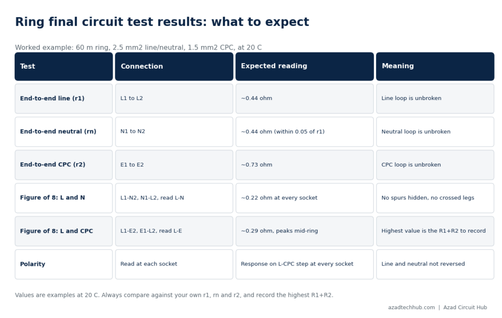
Remember that real readings change with temperature, so compare your results to your own r1, rn and r2 rather than a fixed table. Do not forget to enter the highest R1 + R2 on the test certificate.
Troubleshooting Bad Readings
Once you know how to test a ring main circuit continuity, the readings tell you what is wrong:
- Open circuit in r1, rn or r2: the ring is broken. Check terminations at sockets and the junction boxes.
- r1 and rn differ by more than 0.05 Ω: look for a loose terminal, a line-neutral crossover or an incorrectly joined leg.
- Figure of 8 readings rise at one socket: that socket is on a spur, not the ring.
- Figure of 8 reading far higher everywhere: legs may be crossed, with line from one leg joined to neutral of the other.
- Zero or very low readings: short circuit between conductors, so stop and investigate.
Fix the fault, then repeat all three steps. Never assume a repair worked without re-testing.
Ring Final Circuit Test: Polarity, Radial Circuit and Spurs
A complete ring final circuit test includes more than continuity. The polarity test confirms that line, neutral and earth are on the correct terminals at every accessory. The line and CPC step above helps, and a socket tester or MFT confirms it live. For the full verification sequence, see the testing section of our home wiring and BS 7671 guide.
A radial circuit is simpler: confirm continuity of line, neutral and CPC from the consumer unit to the last outlet, then insulation resistance and polarity. Cable size still matters on both layouts, so use our AC cable size calculator when you design or extend a circuit. Earthing arrangement also affects fault protection, as explained in our TN-S and TN-C-S earthing guide and RCD types guide.
FAQs
These are the questions people ask most about how to test a ring main circuit continuity and the wider ring final circuit test.
Does a ring main go back to the same fuse?
Yes. Both ends of the ring terminate at the same protective device in the consumer unit, whether that is an MCB, an RCBO or an older fuse. That is what makes it a ring.
What are the acceptable results for a ring continuity test?
Line and neutral end-to-end values should match within about 0.05 Ω, the CPC should be in proportion to the line (about 1.6 to 1.7 times for 2.5/1.5 mm² cable), and the figure of 8 readings should be substantially the same at every socket. Record the highest R1 + R2.
Can a ring main be on a 16A MCB?
Electrically a 16 A device still protects 2.5 mm² cable, but it is not the standard ring arrangement in BS 7671 Appendix 15, which uses 30 or 32 A. It will also nuisance trip under normal loads. If the loading is lighter, a properly designed radial is the better route, so ask an electrician.
How to test for circuit continuity?
Isolate and prove dead, zero your instrument, and measure resistance end to end on each conductor. For a ring, how to test a ring main circuit continuity means adding the figure of 8 cross-connection readings at each socket.
How do you test a ring main circuit?
A full test covers continuity (the steps above), insulation resistance, polarity, earth fault loop impedance and RCD operation. Here is how to test a ring main circuit continuity first, then complete the rest of the sequence in order.
Can you take a fused spur off a ring main?
Yes. A fused connection unit can feed a fixed appliance or one socket from the ring, with a fuse appropriate to the cable and load, commonly 13 A at most. Unfused spurs are also allowed, but their total number must not exceed the number of sockets and fused connection units on the ring. Each spur should be checked, which is why the figure of 8 test flags them.
Conclusion
Now you know how to test a ring main circuit continuity: isolate, measure r1, rn and r2, cross-connect for the figure of 8 readings, record the highest R1 + R2, and finish with polarity and insulation resistance. Use a multimeter for quick break-finding and a proper low-resistance ohmmeter or MFT for the real values. For tools, start with our multimeter reviews and panel tester reviews, and return to the Complete Guide to Home Wiring & BS 7671 (UK) for the rest of the installation picture.
Get new guides in your feed. Follow Electrical Insights on LinkedIn for new electrical standards guides, calculators and design tips from Azad Circuit Hub.