
Underground Cable Laying Guide: Methods & IEC/IS Standards
Underground cable laying is widely used for power distribution, industrial plants, commercial buildings, solar projects, substations, and utility networks. Proper installation protects cables from mechanical damage, moisture, excessive heat, soil pressure, and future excavation work.
A good installation starts with route planning and cable selection. It also requires the correct trench depth, bedding, cable spacing, warning tape, backfilling, and testing. IEC and Indian Standards provide useful guidance for cable construction, current-carrying capacity, installation practices, and testing.
This guide explains the main underground cable laying methods, typical trench requirements, cable separation, protection systems, and important IEC/IS standards used for power cable installations.
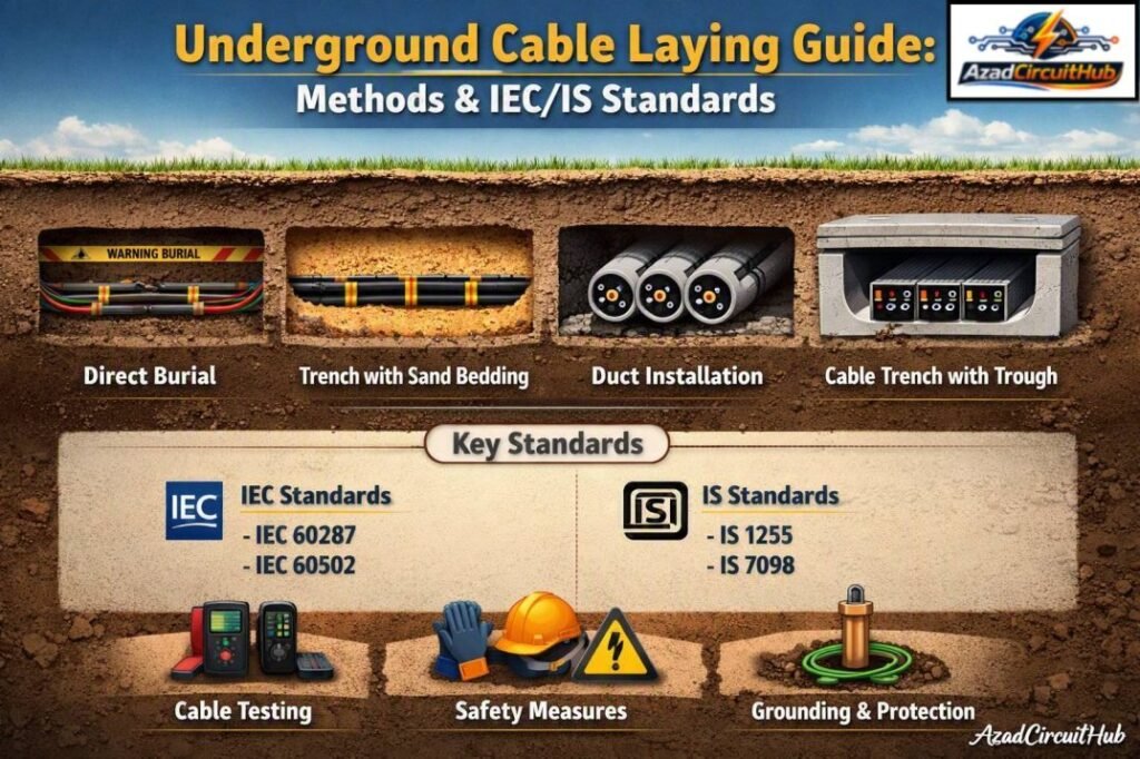
Table of Contents
Table of Contents
Underground Cable Laying: Quick Reference Table
| Item | Typical Requirement | Main Consideration |
|---|---|---|
| Low-voltage cable depth | About 600–750 mm | Site conditions and local rules |
| Medium-voltage cable depth | About 750–1000 mm or more | Utility and project specification |
| Cable bedding | Clean sand or approved fine material | Prevents sharp-point damage |
| Warning tape | Above buried cable | Indicates cable route |
| Cable spacing | Based on cable size and heat dissipation | Ampacity and grouping |
| Minimum bending radius | Manufacturer specified | Depends on cable construction |
| Cable pulling tension | Manufacturer specified | Prevents conductor/sheath damage |
| Cable trench drainage | Required where water may collect | Prevents prolonged water exposure |
| Cable identification | Required at suitable intervals | Easier maintenance |
| Cable testing | Before and after installation | Confirms installation integrity |
The values in this table are practical planning values rather than universal code limits. The applicable standard, cable manufacturer’s instructions, utility requirements, voltage level, soil condition, and project specification should always be checked before construction.
Main Underground Cable Laying Methods
There are several methods for installing underground power cables. The most suitable method depends on voltage level, cable construction, soil conditions, traffic loading, available space, and future maintenance requirements.
| Method | Typical Application | Main Advantage |
|---|---|---|
| Direct burial | Distribution and utility cables | Simple and economical |
| Cable trench | Industrial and commercial sites | Easy inspection and maintenance |
| Duct installation | Roads, buildings, congested areas | Excellent mechanical protection |
| Cable tunnel | Large utility networks | Accessible and expandable |
| HDD installation | Roads, railways and waterways | Minimal surface excavation |
| Concrete-encased duct bank | Heavy traffic areas | High mechanical protection |
| Open cable trench | Substations and industrial plants | Easy access |
Direct burial is suitable when the route is stable and future access is not a major concern. Ducts are often preferred where cables pass under roads or areas that may be excavated later.
Underground Cable Trench Design
Trench design is one of the most important parts of underground cable laying. The trench must provide enough space for cable installation while maintaining suitable thermal conditions.
A typical trench consists of prepared soil, bedding material, cables, protective covering, warning tape, and compacted backfill.
Typical Cable Trench Arrangement
| Layer | Typical Material | Purpose |
|---|---|---|
| Bottom | Compacted soil | Stable foundation |
| Bedding | Clean sand or selected material | Protects cable sheath |
| Cable layer | Power cables | Energy transmission |
| Surrounding layer | Sand or approved fine fill | Mechanical protection |
| Protection | Tiles, slabs or approved cover | Protects against excavation |
| Warning layer | Warning tape | Identifies buried cable |
| Backfill | Selected excavated material | Restores trench |
| Surface | Soil, paving or concrete | Final finish |
The trench width should allow safe cable installation, the required spacing between circuits, and enough room for heat dissipation. It should also account for future cables if the design includes spare capacity.
For projects with several circuits, thermal calculations become particularly important because closely grouped cables can operate at higher temperatures.
If you are designing the excavation and cable fill, use a dedicated Cable Trench Fill Calculator to estimate trench capacity and avoid overcrowding before finalizing the route.
Cable Bedding and Backfilling
The cable should normally be installed on a smooth, stable bedding layer free from stones, metal fragments, construction waste, and other sharp objects.
Sand or another approved fine material is commonly used around buried cables. The selected material should be compatible with the project’s thermal design because soil thermal resistivity can have a direct effect on cable ampacity.
Backfilling should be performed carefully in layers. Heavy compaction equipment should not be used directly over cables unless the installation has been specifically designed for that loading.
| Backfill Issue | Possible Problem |
|---|---|
| Sharp stones | Cable sheath damage |
| Poor compaction | Ground settlement |
| Wet or unsuitable soil | Changed thermal conditions |
| Excessive thermal resistivity | Reduced cable ampacity |
| Construction debris | Mechanical damage |
| Poor drainage | Water accumulation |
| Incorrect cover depth | Increased mechanical risk |
Cable Spacing and Grouping
Cable spacing is not simply a mechanical requirement. It also affects heat dissipation and therefore the permissible current.
When multiple power cables are installed close together, the heat produced by one cable can affect neighboring cables. This may require grouping or thermal derating factors.
| Installation Condition | Design Concern |
|---|---|
| Single cable circuit | Basic thermal calculation |
| Multiple circuits side by side | Grouping factor |
| Cables in ducts | Duct thermal resistance |
| Cables in concrete ducts | Higher thermal resistance |
| Different voltage circuits | Required separation |
| Power and control cables | Electromagnetic interference |
| Communication cables | Noise and induced voltage |
Cable spacing should therefore be based on the manufacturer’s data, applicable installation standard, calculated ampacity, and project requirements rather than a single universal distance.
Underground Cable Laying in Ducts
Duct installation is commonly used beneath roads, parking areas, railway crossings, building entrances, and other locations where direct burial may create maintenance problems.
The duct should have a suitable internal diameter for the cable and pulling operation. Excessive bends should be avoided because they increase pulling tension.
A draw rope or suitable pulling system may be installed in the duct before cable installation.
The duct route should also provide suitable drainage where water accumulation is possible. Sealing systems may be required at building entries and other locations to prevent water, gas, or pests from entering the structure.
Cable Pulling and Installation
Cable pulling must be controlled carefully. Excessive pulling force can damage the conductor, insulation, metallic screen, armour, or outer sheath.
The cable manufacturer’s specified maximum pulling tension and minimum bending radius should always be followed.
| Installation Parameter | Why It Matters |
|---|---|
| Pulling tension | Prevents conductor and sheath damage |
| Sidewall pressure | Important at bends |
| Bending radius | Prevents insulation and sheath stress |
| Pulling speed | Helps maintain installation control |
| Cable rollers | Reduce friction |
| Lubricant | May be needed for duct pulling |
| Drum direction | Prevents cable twisting |
| Cable ends | Must remain sealed |
Cable drums should be inspected before use. Damaged drums, crushed cable sections, or open cable ends should not be accepted without proper inspection and engineering approval.
Separation Between Power and Control Cables
Power cables, control cables, instrumentation cables, and communication cables may need separation to reduce electromagnetic interference and improve system reliability.
The exact arrangement depends on voltage level, cable construction, screening, installation method, and project requirements.
In industrial facilities, segregation is particularly important around variable-frequency drives, large motors, transformers, and switching equipment.
A common approach is to use separate trenches, separate ducts, or physical barriers where required.
Underground Cable Protection
Mechanical protection becomes important where the cable may be exposed to vehicles, excavation, building loads, road crossings, or other external forces.
Common protection methods include:
- Reinforced concrete covers
- Cable protection tiles
- Concrete-encased ducts
- Steel pipes at special crossings
- HDPE or PVC ducts
- Warning tape
- Marker posts
- Protective slabs
Cable markers should identify the route and provide useful information such as circuit identification and voltage where required by the project specification.
Underground Cable Laying Standards: IEC and IS
Several standards may apply to underground cable installations. No single standard covers every part of the installation.
| Standard | Subject | Relevance |
|---|---|---|
| IEC 60364-5-52 | Selection and erection of wiring systems | Cable installation principles |
| IEC 60502-1 | Power cables with extruded insulation up to 1 kV | Cable construction |
| IEC 60502-2 | Power cables with extruded insulation from 6 kV to 30 kV | MV cable systems |
| IEC 60287 series | Electric cables – current rating | Cable ampacity calculations |
| IEC 60840 | Power cables above 30 kV up to 150 kV | HV cable systems |
| IEC 62067 | Power cables above 150 kV up to 500 kV | EHV cable systems |
| IS 1255 | Code of practice for installation and maintenance of power cables | Indian cable installation practice |
| IS 7098 series | Cross-linked polyethylene insulated cables | XLPE power cables |
| IS 1554 series | PVC insulated heavy-duty electric cables | PVC cable systems |
The latest applicable edition and project-specific amendments should be checked before using any standard for construction. Utility specifications can also impose requirements that are more restrictive than general installation guidance. Know more about IEC Standard for Underground Cable Laying
Cable Depth and Cover Requirements
Cable burial depth should be selected according to voltage, cable type, location, mechanical loading, local regulations, and utility requirements.
Road crossings and areas exposed to heavy vehicles generally require additional mechanical protection.
| Location | Typical Design Approach |
|---|---|
| Landscaped area | Standard burial with warning protection |
| Industrial yard | Increased protection where vehicles operate |
| Road crossing | Duct or concrete protection commonly used |
| Railway crossing | Special authority-approved design |
| Building entry | Duct and water-sealing arrangement |
| Agricultural area | Consider future excavation and farming activity |
Depth alone does not guarantee protection. A relatively deep cable can still be damaged by excavation equipment if the route is not marked and documented.
For large projects, cable route drawings should show cable identification, trench dimensions, crossings, joints, ducts, termination points, and warning marker locations.
Earthing and Cable Armour
Armoured cables require appropriate bonding and earthing arrangements. The method depends on the cable construction, voltage level, fault current, installation system, and applicable standard.
For single-core AC cables, special attention is needed because metallic armour, screens, and sheaths can develop induced voltages and circulating currents.
Cable bonding should therefore be designed rather than treated as a simple connection to earth.
The earth continuity and fault-current capability of metallic screens, sheaths, armour, and protective conductors should be verified during design.
Underground Cable Jointing and Termination
Cable joints and terminations are common points of failure if workmanship is poor. They should be installed by trained personnel using approved kits and following the manufacturer’s instructions.
Before jointing, cable ends should be protected from moisture and contamination.
| Activity | Important Check |
|---|---|
| Cable preparation | Correct dimensions |
| Insulation stripping | No conductor damage |
| Screen removal | Correct length |
| Lug installation | Correct crimping |
| Joint assembly | Manufacturer procedure |
| Sealing | Moisture protection |
| Earthing | Correct bonding |
| Identification | Circuit and phase marking |
For medium- and high-voltage cables, additional tests may be required after jointing and termination.
Testing Before Energization
Testing should be carried out before the cable is energized. The exact test sequence depends on cable voltage, insulation system, applicable standards, utility requirements, and manufacturer recommendations.
Typical checks may include:
- Conductor continuity
- Phase identification
- Insulation resistance
- Sheath integrity
- Armour continuity
- Screen continuity
- Conductor resistance
- High-voltage or withstand testing where applicable
- VLF or other diagnostic testing for suitable MV systems
- Visual inspection of terminations and joints
Test results should be recorded and compared with project acceptance criteria.
Common Underground Cable Installation Mistakes
Several installation errors can reduce cable life or create immediate operational problems.
| Mistake | Consequence |
|---|---|
| Incorrect trench depth | Mechanical damage risk |
| Small bending radius | Cable insulation stress |
| Excessive pulling force | Internal cable damage |
| Poor bedding | Sheath damage |
| Overcrowded trench | Cable overheating |
| No route markers | Future excavation damage |
| Poor jointing | Moisture ingress and faults |
| Incorrect cable spacing | Thermal derating |
| Unsealed cable ends | Moisture contamination |
| Poor documentation | Difficult future maintenance |
A thermal check should be completed whenever the installation arrangement changes. Increasing the number of cables in a trench can significantly change the heat dissipation conditions.
For complex installations, a Cable Trench Fill Calculator can also help check available trench space before adding new circuits.
Underground Cable Laying Inspection Checklist
A practical inspection checklist can prevent many installation problems.
| Inspection Point | Status |
|---|---|
| Cable route approved | ☐ |
| Cable type and size verified | ☐ |
| Drum inspected | ☐ |
| Trench depth checked | ☐ |
| Bedding approved | ☐ |
| Cable spacing checked | ☐ |
| Bending radius maintained | ☐ |
| Pulling tension controlled | ☐ |
| Cable identification installed | ☐ |
| Mechanical protection installed | ☐ |
| Warning tape installed | ☐ |
| Backfill approved | ☐ |
| Route markers installed | ☐ |
| Testing completed | ☐ |
| As-built drawings updated | ☐ |
The inspection should be documented before the trench is permanently closed. Photographs, cable route measurements, test reports, and as-built drawings can be valuable during future maintenance.
Final Considerations for Underground Cable Laying
Successful underground cable laying depends on more than simply placing a cable inside a trench. Cable selection, thermal design, burial depth, mechanical protection, spacing, earthing, jointing, testing, and documentation all influence long-term reliability.
IEC standards provide an important technical framework, while IS standards such as IS 1255 are particularly useful for installation practice in India. Local electricity utilities, authorities, and project specifications should also be checked because their requirements can vary.
For projects with multiple cable circuits, verify both the physical trench capacity and thermal loading before construction. A properly planned Cable Trench Fill Calculator check can help identify space constraints early and reduce costly modifications later.
Frequently Asked Questions
What is the standard depth for underground electrical cables?
There is no single universal burial depth for every underground electrical cable. Typical project designs may use around 600–750 mm for lower-voltage installations and greater cover for medium-voltage circuits or areas exposed to traffic. The final depth should follow the applicable standard, utility requirements, cable type, location, and mechanical protection arrangement.
Which standard is used for underground cable installation in India?
IS 1255 is a key Indian standard covering the code of practice for installation and maintenance of power cables. Other standards, such as the IS 7098 series and IS 1554 series, apply to particular cable constructions. IEC standards may also be specified for cable design, installation, testing, and current-rating calculations.
Can underground cables be laid directly in soil?
Yes. Direct burial is a common underground cable laying method when the cable and route are suitable for it. The installation normally requires suitable bedding, adequate cover, warning identification, mechanical protection where necessary, and consideration of soil thermal resistivity. Road crossings and high-risk areas may require ducts or additional protection.
How far apart should underground power cables be?
Cable spacing depends on cable size, voltage, installation method, grouping, thermal resistivity, and the required current-carrying capacity. Multiple circuits installed close together can require derating. Therefore, spacing should be established from the applicable cable manufacturer’s data, thermal calculations, and project requirements rather than relying on one fixed distance.
What tests are required before energizing an underground cable?
Typical tests include conductor continuity, phase identification, insulation resistance, sheath integrity, screen or armour continuity, and conductor resistance. Medium- and high-voltage systems may require additional withstand or diagnostic tests. The exact test procedure should follow the cable manufacturer’s instructions, applicable standards, and project or utility specifications.
Get new guides in your feed. Follow Electrical Insights on LinkedIn for new electrical standards guides, calculators and design tips from Azad Circuit Hub.
#UndergroundCableLaying, #CableInstallation, #ElectricalEngineering, #IECStandards, #ISStandards, #CableTrenching, #PowerCables, #ElectricalCables, #CableTrench, #ElectricalInstallation
