
Minimum Electrical Clearance as per IEC Standards: Best Guide
Electrical insulation safety depends heavily on maintaining the correct air gap between conductive parts. This air gap, known as electrical clearance, prevents flashover, arcing, and insulation breakdown under normal and fault conditions. Understanding the Minimum Electrical Clearance as per IEC is essential for engineers, panel builders, and maintenance professionals working on low-voltage and high-voltage systems.
Whether you are designing switchboards, busbar systems, motor control centers, or industrial panels, proper clearance ensures compliance with international safety standards. It also reduces the risk of equipment failure and improves operational reliability.
Many designers confuse general electrical clearance with phase spacing. While both are connected, they serve different purposes. If your concern is conductor-to-conductor spacing, refer to Phase to Phase Clearance as per IEC for a detailed breakdown.
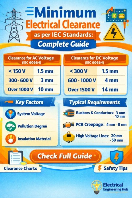
Table of Contents
Table of Contents
This guide explains how IEC standards define clearance, how pollution and altitude affect it, and how to determine the right values for your application.
What Is Electrical Clearance?
Electrical clearance is the shortest distance through air between two conductive parts. These conductive parts may be:
- Phase to phase
- Phase to neutral
- Phase to earth
- Busbar to enclosure
- Live parts to grounded metallic surfaces
The main purpose of clearance is to prevent dielectric breakdown in air.
Know more about Phase to Phase Clearance as per IEC 61439
When voltage increases, the electric field strength between conductors also rises. If the gap is too small, arcing can occur. This may damage insulation, trip protection systems, or cause fire hazards.
Why clearance matters
Proper clearance helps in:
| Factor | Benefit |
|---|---|
| Arc prevention | Avoids flashover between conductors |
| Equipment life | Reduces insulation stress |
| Safety compliance | Meets IEC regulations |
| System reliability | Prevents unplanned shutdowns |
Clearance is not the same as conductor spacing. For example, in switchgear systems, the general air gap follows insulation coordination rules, while Phase to Phase Clearance as per IEC focuses specifically on spacing between live phases.
In practical panel design, both must be checked.
Which IEC Standards Define Minimum Clearance?
Different IEC standards apply depending on the equipment type and voltage level. This is where many engineers make mistakes.
Here are the main standards.
IEC 61439
IEC 61439 applies to low-voltage switchgear and controlgear assemblies.
It covers:
- Distribution boards
- Motor control centers
- Power panels
- Busbar chambers
This standard often refers to insulation coordination based on rated impulse withstand voltage.
Find all about Busbar Clearance as per IEC 61439: Minimum Distance Chart
Typical applications:
| Equipment | Voltage Range |
|---|---|
| LV panels | Up to 1000V AC |
| Busbar trunking | Up to 1000V |
| Industrial enclosures | Up to 690V |
If you are designing busbar layouts, combining this with Phase to Phase Clearance as per IEC gives better design accuracy.
IEC 60664
IEC 60664 is the primary insulation coordination standard for low-voltage systems.
It defines:
- Clearance distances
- Creepage distances
- Pollution degrees
- Overvoltage categories
This standard is often used as the base reference for calculating the Minimum Electrical Clearance as per IEC.
Find all about Phase to Phase Clearance in 132 kV
IEC 61936
IEC 61936 applies to power installations above 1kV.
It is mainly used for:
- Substations
- High-voltage switchyards
- Industrial HV systems
This standard considers:
- Switching surges
- Lightning impulse
- Safety clearances
Quick standard selection guide
| Application | Standard |
|---|---|
| LV switchboard | IEC 61439 |
| PCB and insulation coordination | IEC 60664 |
| HV substation | IEC 61936 |
Choosing the correct standard is the first step before calculating clearance.
Know in detail about 33kV Phase to Phase Clearance
Minimum Clearance by Pollution Degree
Pollution degree has a major effect on insulation performance.
IEC 60664 defines four pollution levels based on environmental contamination.
Pollution degree classification
| Pollution Degree | Environment Type | Example |
|---|---|---|
| PD1 | Clean and dry | Laboratory equipment |
| PD2 | Non-conductive contamination | Indoor control panels |
| PD3 | Conductive pollution possible | Industrial plants |
| PD4 | Persistent conductive pollution | Outdoor exposed systems |
Higher pollution increases leakage paths and weakens insulation.
Use our free tool Phase to Phase Clearance Calculator
Typical minimum clearance multipliers
| Pollution Degree | Multiplier |
|---|---|
| PD1 | 1.0x |
| PD2 | 1.2x |
| PD3 | 1.5x |
| PD4 | 2.0x |
Know more about IEC Standard for Busbar Clearance
Example
For a base clearance of 8 mm:
| Pollution Degree | Adjusted Clearance |
|---|---|
| PD1 | 8 mm |
| PD2 | 9.6 mm |
| PD3 | 12 mm |
| PD4 | 16 mm |
Industrial switchboards usually fall under PD3.
This is why Phase to Phase Clearance as per IEC in dusty factories is often larger than standard indoor panels.
Always identify the operating environment before finalizing the design.
Minimum Clearance by Altitude
Air insulation strength decreases with altitude because air density becomes lower.
IEC standards require correction factors above 2000 meters.
This is critical for:
- Mountain installations
- Mining sites
- Remote substations
Altitude correction factors
| Altitude (m) | Correction Factor |
|---|---|
| 0–2000 | 1.00 |
| 3000 | 1.14 |
| 4000 | 1.29 |
| 5000 | 1.48 |
Formula
Adjusted Clearance = Base Clearance × Altitude Factor
Example
Base clearance = 10 mm
Installation altitude = 4000 m
Adjusted clearance:
10 × 1.29 = 12.9 mm
Explore in detail IEC 61936 Clearance Table
This means a system designed at sea level may fail at high altitude if the gap is not increased.
For conductor spacing calculations, engineers should also review Phase to Phase Clearance as per IEC because altitude affects phase insulation equally.
Ignoring altitude is one of the most common compliance issues.
Minimum Electrical Clearance Chart (Summary Table)
The table below combines voltage, pollution degree, and altitude for quick reference.
Consolidated IEC clearance chart
| Voltage | Base Clearance (PD2) | PD3 Clearance | PD3 at 4000m |
|---|---|---|---|
| 230V | 3 mm | 4.5 mm | 5.8 mm |
| 400V | 5.5 mm | 8.2 mm | 10.5 mm |
| 690V | 8 mm | 12 mm | 15.4 mm |
| 1000V | 14 mm | 21 mm | 27 mm |
This table gives a practical overview of the Minimum Electrical Clearance as per IEC for most industrial applications.
Use it as a reference, but always verify with the latest IEC standard edition.
Key design tips
- Increase spacing for humid environments
- Consider transient overvoltage
- Check enclosure IP rating
- Verify busbar orientation
- Apply altitude correction
These factors improve dielectric reliability.
Know more about IEC Standard for Creepage Distance
Electrical Clearance vs. Creepage Distance
Many people use these terms interchangeably, but they are different.
Electrical clearance
The shortest distance through air.
Example:
Busbar to busbar air gap.
Creepage distance
The shortest distance along the insulation surface.
Example:
Distance along an insulator body.
Know more about IEC Standard for Creepage Distance
Comparison table
| Parameter | Clearance | Creepage |
|---|---|---|
| Path | Through air | Along surface |
| Affected by altitude | Yes | No |
| Affected by pollution | Indirectly | Directly |
| Main risk | Flashover | Surface tracking |
For panel design:
- Clearance prevents arcing
- Creepage prevents leakage current
Both are essential.
In busbar systems, Phase to Phase Clearance as per IEC handles air spacing, while creepage ensures insulation surface integrity.
Ignoring either one can result in non-compliance.
Use our online tool Creepage Distance Calculator
Frequently Asked Questions
What is minimum electrical clearance as per IEC?
The Minimum Electrical Clearance as per IEC is the shortest safe air distance between conductive parts to prevent dielectric breakdown. It depends on voltage, pollution degree, and altitude.
Which IEC standard defines electrical clearance requirements?
IEC 60664 is the primary standard for insulation coordination. IEC 61439 applies it for low-voltage assemblies, while IEC 61936 covers installations above 1kV.
How does altitude affect minimum electrical clearance?
Higher altitude reduces air density, which lowers insulation strength. IEC requires increased clearance above 2000 meters using correction factors.
What is the difference between IEC 61439 and IEC 60664 clearance requirements?
IEC 60664 defines the technical insulation rules. IEC 61439 applies those rules to practical switchgear and panel construction.
Final Thoughts
Correct electrical spacing is one of the most important parts of safe electrical design. Understanding the Minimum Electrical Clearance as per IEC helps reduce flashover risk, improve insulation life, and maintain regulatory compliance.
Always evaluate:
- Operating voltage
- Pollution degree
- Installation altitude
- Equipment type
- Overvoltage category
For complete conductor spacing analysis, especially inside switchboards and busbar chambers, Phase to Phase Clearance as per IEC should be reviewed alongside clearance calculations.
Get new guides in your feed. Follow Electrical Insights on LinkedIn for new electrical standards guides, calculators and design tips from Azad Circuit Hub.
#MinimumElectricalClearance, #IECStandards, #ElectricalSafety, #BusbarClearance, #SwitchgearDesign, #IEC61439, #ElectricalEngineering, #ClearanceDistance, #PowerDistribution, #IndustrialSafety
