
66kV Phase to Phase Clearance: IEC Requirements, Distance Chart and Practical Guide
| Parameter | Typical value for a 66 kV system |
|---|---|
| Nominal system voltage | 66 kV |
| Typical highest voltage for equipment (Um) | 72.5 kV |
| Typical minimum air clearance baseline | 630 mm |
| Clearance type | Phase-to-phase / phase-to-earth |
| Main IEC reference | IEC 61936-1 |
| Insulation coordination reference | IEC 60071 series |
| Application | Outdoor substations, switchyards, AIS equipment |
| Important design factor | Site conditions, insulation level and geometry |
The 66kV Phase to Phase Clearance is a critical design value for substations, switchyards, overhead line equipment and air-insulated switchgear. Adequate spacing prevents flashover between energized conductors and provides sufficient electrical insulation under normal operating and transient conditions.
For a 66 kV network, designers normally consider the equipment’s highest voltage for equipment, which is commonly 72.5 kV. The final air clearance should not be selected from nominal voltage alone. Insulation level, impulse withstand voltage, conductor arrangement, altitude, pollution, switching surges and the type of electrical equipment must also be considered.
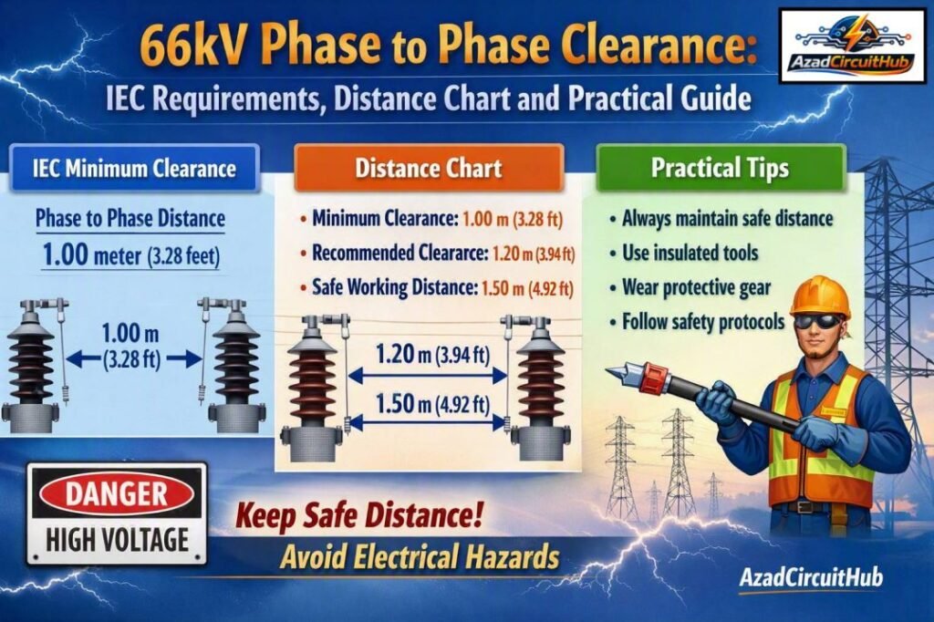
Table of Contents
Table of Contents
66kV Phase to Phase Clearance IEC Distance
For equipment in the 66 kV class, a commonly used IEC design baseline is associated with a 72.5 kV highest voltage for equipment. IEC 61936-1 provides requirements for power installations exceeding 1 kV AC, while IEC 60071 addresses insulation coordination.
| Voltage class | Highest voltage for equipment Um | Typical minimum air clearance* |
|---|---|---|
| 33 kV | 36 kV | Around 320 mm |
| 66 kV | 72.5 kV | Around 630 mm |
| 110 kV | 123 kV | Around 1,100 mm |
| 132 kV | 145 kV | Around 1,300 mm |
| 220 kV | 245 kV | Around 2,100 mm |
| 400 kV | 420 kV | Around 3,600 mm |
*These values should be treated as design reference values rather than a universal construction rule. The applicable IEC edition, insulation coordination study, equipment standards, installation arrangement and site conditions must be checked before finalizing dimensions.
For a 66 kV installation, the commonly referenced minimum air gap is therefore about 630 mm. However, the actual design clearance can be greater where the installation has unusual conductor geometry, higher insulation requirements, high altitude or severe environmental conditions.
Why 66kV Phase to Phase Clearance Matters
The purpose of electrical clearance is to prevent an unintended arc through air. Air provides insulation between energized conductors, but its dielectric strength is affected by several factors.
A substation may operate at a steady 66 kV, yet the insulation system can experience much higher temporary or transient voltages. Lightning impulses and switching surges can create high electrical stress across relatively short distances.
Correct spacing helps prevent:
- Phase-to-phase flashover
- Phase-to-earth flashover
- Equipment damage
- Busbar faults
- Unplanned outages
- Arc-related fire hazards
- Personnel safety risks
Clearance is different from creepage distance. Clearance is the shortest distance through air between two conductive parts. Creepage is the shortest path along an insulating surface. Both must be considered when designing electrical equipment.
66 kV Phase Clearance Table
The following table provides a practical reference for common 66 kV substation components.
| Installation area | Clearance consideration | Typical design approach |
|---|---|---|
| 66 kV busbars | Phase-to-phase air gap | ≥ 630 mm baseline |
| Busbar to earth | Phase-to-earth air gap | Check against insulation coordination |
| Disconnectors | Open contact and phase spacing | Manufacturer and IEC requirements |
| Circuit breakers | Terminal and phase spacing | Manufacturer drawings |
| CTs and VTs | Primary terminal spacing | Equipment-specific |
| Cable termination | Phase spacing | Manufacturer’s certified dimensions |
| Outdoor conductors | Phase-to-phase spacing | IEC plus mechanical design |
| Switchyard structures | Live part to steelwork | Phase-to-earth clearance |
| Busbar supports | Insulation and creepage | Insulator manufacturer’s data |
The 630 mm value should not simply be copied into every substation drawing. Equipment manufacturers may specify larger terminal spacing, and the physical arrangement may require additional margin.
If you are also working on low-voltage assembly clearances, see our guide to phase to phase clearance as per iec 61439 for the appropriate LV switchgear context. Remember that IEC 61439 is a low-voltage assembly standard and is not the primary clearance standard for a 66 kV outdoor substation.
Factors That Affect 66kV Phase to Phase Clearance
1. Highest Voltage for Equipment
The nominal system voltage is only the starting point. A 66 kV system is commonly associated with equipment having a highest voltage for equipment of 72.5 kV.
This value is important when determining insulation requirements and selecting suitable electrical equipment.
2. Lightning Impulse Withstand Voltage
Lightning impulse withstand voltage, often abbreviated LIWV or BIL in some engineering practices, is a major insulation coordination parameter.
Higher withstand requirements can lead to increased required clearances. The selected value should therefore be confirmed from the insulation coordination study and equipment specifications.
3. Switching Surges
Switching operations can produce transient overvoltages. Circuit breakers, disconnectors and long transmission lines can all contribute to switching stresses.
The clearance must provide adequate withstand capability against the expected transient voltage.
4. Altitude
Air insulation becomes less effective as altitude increases because atmospheric pressure decreases. A clearance suitable at sea level may require correction at a high-altitude installation.
For this reason, an elevated site should not use a standard clearance value without checking the applicable altitude correction.
5. Atmospheric Pollution
Dust, salt, industrial contamination and moisture can reduce insulation performance. Pollution is especially important for outdoor substations.
Although pollution primarily affects creepage requirements, the overall insulation design must consider environmental conditions as part of the complete coordination process.
6. Conductor Geometry
The shape and arrangement of conductors influence electric field concentration. Sharp edges and irregular conductive surfaces can produce localized electrical stress.
Smooth busbars, suitable fittings and correct conductor spacing help maintain a reliable insulation system.
Phase-to-Phase vs Phase-to-Earth Clearance
These two dimensions are often confused during substation design.
| Clearance | Meaning | Example |
|---|---|---|
| Phase-to-phase | Distance between two energized phases | R phase to Y phase |
| Phase-to-earth | Distance between an energized part and grounded structure | Busbar to steel support |
| Phase-to-neutral | Distance between phase and neutral conductor | Used where neutral exists |
| Conductor-to-ground | Live conductor to earth potential | Outdoor line conductor to structure |
A design can have sufficient phase-to-phase spacing but still fail to provide adequate phase-to-earth clearance. Both dimensions should therefore appear clearly on engineering drawings.
How to Calculate 66kV Phase to Phase Clearance
There is no simple calculation based only on the number 66 kV. The engineering process normally follows insulation coordination principles.
A simplified workflow is:
- Identify the nominal system voltage.
- Determine the highest voltage for equipment.
- Establish the required insulation level.
- Determine lightning and switching withstand requirements.
- Select the applicable IEC requirements.
- Determine minimum air clearances.
- Apply altitude and environmental considerations.
- Check equipment manufacturer’s dimensions.
- Verify mechanical movement and conductor swing.
- Add appropriate engineering margin where required.
For a typical 66 kV AIS installation, the designer may begin with the applicable 72.5 kV equipment class and a reference clearance around 630 mm, then verify whether the particular installation requires a larger value.
Common 66 kV Substation Clearance Mistakes
Several errors can create problems during design or construction.
Using Nominal Voltage Only
Designing directly from 66 kV without considering the 72.5 kV equipment class can result in an incomplete insulation assessment.
Confusing Clearance With Creepage
A 630 mm air gap does not mean that the required creepage distance is also 630 mm. Creepage depends strongly on pollution severity and insulator design.
Ignoring Equipment Manufacturer Drawings
Switchgear, CTs, VTs, disconnectors and surge arresters may have specific minimum terminal and phase spacing requirements.
Forgetting Mechanical Movement
Outdoor conductors can move because of wind, thermal expansion and short-circuit forces. The minimum spacing must remain adequate under the applicable operating conditions.
Ignoring Altitude
High-altitude substations require special attention because reduced air density decreases dielectric strength.
IEC Standards for 66 kV Clearance
The main standards should be selected according to the installation and equipment type.
| Standard | Main purpose |
|---|---|
| IEC 61936-1 | Power installations exceeding 1 kV AC |
| IEC 60071-1 | Insulation coordination definitions and principles |
| IEC 60071-2 | Application guidance for insulation coordination |
| IEC 62271 series | High-voltage switchgear and controlgear |
| IEC 60840 | Power cables above 30 kV up to 150 kV, depending on scope |
One important point is that IEC 61439 should not be treated as the governing standard for 66 kV air clearance. IEC 61439 concerns low-voltage switchgear and controlgear assemblies. Therefore, a search for phase to phase clearance as per iec 61439 should be interpreted carefully when the actual project voltage is 66 kV.
Practical Design Checklist
Before approving a 66 kV substation layout, check the following:
- Confirm the system’s nominal voltage.
- Confirm the equipment’s Um value.
- Check the insulation coordination study.
- Verify phase-to-phase clearance.
- Verify phase-to-earth clearance.
- Check creepage distances.
- Review lightning impulse withstand level.
- Consider switching overvoltages.
- Apply altitude corrections where necessary.
- Consider pollution and environmental conditions.
- Check conductor movement.
- Verify equipment manufacturer’s drawings.
- Confirm clearances during maintenance and isolation.
- Review the final arrangement against the applicable IEC edition.
For engineers comparing requirements across voltage levels, our phase to phase clearance as per iec 61439 resource can also help explain how LV assembly spacing differs from high-voltage substation design.
Frequently Asked Questions
What is the minimum 66kV Phase to Phase Clearance?
For a typical 66 kV installation using 72.5 kV as the highest voltage for equipment, around 630 mm is commonly used as an IEC-based reference value for minimum air clearance. The final project value must be verified against IEC 61936-1, insulation coordination requirements and equipment-specific data.
Is 630 mm enough for a 66 kV substation?
Not necessarily for every installation. Around 630 mm can serve as a reference baseline, but the required spacing may increase because of altitude, insulation level, conductor arrangement, equipment design, mechanical movement or other project conditions.
Which IEC standard covers 66 kV phase clearance?
IEC 61936-1 is a key standard for electrical power installations exceeding 1 kV AC. IEC 60071 provides the insulation coordination framework. High-voltage switchgear also falls under the relevant IEC 62271 series standards.
Does IEC 61439 apply to 66 kV clearance?
No. IEC 61439 is primarily for low-voltage switchgear and controlgear assemblies. It is not the governing standard for air clearances in a 66 kV substation. For 66 kV installations, IEC 61936-1 and IEC 60071 are much more relevant.
What is the difference between phase-to-phase and phase-to-earth clearance?
Phase-to-phase clearance is the air distance between two energized phases. Phase-to-earth clearance is the air distance between an energized component and grounded equipment or structure. Both are essential for reliable insulation coordination.
Final Takeaway
The 66kV Phase to Phase Clearance should be selected through an insulation coordination process rather than by nominal voltage alone. For a typical 66 kV system with 72.5 kV highest voltage for equipment, approximately 630 mm is a useful IEC-based reference point, but it should never replace a project-specific engineering check.
IEC 61936-1, IEC 60071 and the relevant IEC 62271 equipment standards provide the appropriate framework for high-voltage installations. Always verify the latest applicable standard edition, equipment manufacturer’s requirements, altitude, environmental conditions and the complete substation layout before finalizing the clearance.
Get new guides in your feed. Follow Electrical Insights on LinkedIn for new electrical standards guides, calculators and design tips from Azad Circuit Hub.
#66kVPhaseToPhaseClearance, #66kVClearance, #IECStandards, #ElectricalClearance, #HighVoltageSafety, #PhaseToPhaseClearance, #ElectricalEngineering, #HVSystems, #IEC60071, #SubstationDesign
