
11kV Phase to Phase Clearance as per IEC
11kV electrical systems are widely used in utility substations, industrial plants, commercial facilities, and distribution networks. Correct conductor spacing is essential because an inadequate air gap can lead to flashover, insulation failure, equipment damage, or serious safety hazards.
The required 11kV Phase to Phase Clearance depends on the equipment type, rated insulation level, impulse withstand voltage, installation conditions, and the applicable IEC standard. It should therefore not be selected from voltage alone.
For practical design work, IEC 62271 series standards are important for medium-voltage switchgear and controlgear, while IEC 61936-1 provides requirements for power installations above 1 kV AC. IEC 60071 is also relevant when insulation coordination and withstand levels are being established.
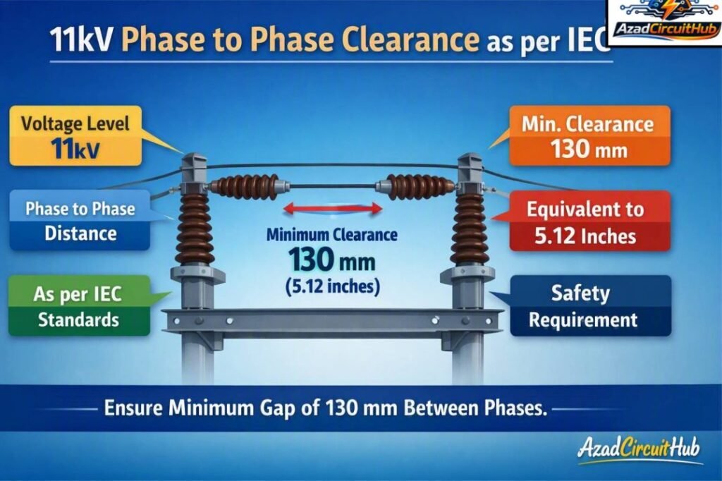
Table of Contents
Table of Contents
11kV Phase to Phase Clearance at a Glance
The following table provides commonly used minimum air-clearance values associated with 12 kV class medium-voltage equipment. The exact value must be verified against the applicable equipment standard and insulation level.
| Parameter | Typical 11 kV / 12 kV Class Value | Applicable Consideration |
|---|---|---|
| Nominal system voltage | 11 kV | Medium-voltage distribution |
| Highest system voltage | 12 kV | Common IEC equipment class |
| Typical power-frequency withstand | 28 kV rms | Equipment insulation level |
| Typical lightning impulse withstand | 75 kV peak | Basic insulation level |
| Typical minimum phase-to-earth air clearance | About 90 mm | Equipment-dependent |
| Typical minimum phase-to-phase air clearance | About 120 mm | Equipment-dependent |
| Recommended design approach | Verify equipment standard | Do not rely on voltage alone |
Quick 11kV Clearance Table
| Clearance Type | Typical Minimum for 12 kV Class Equipment |
|---|---|
| Phase to phase | 120 mm |
| Phase to earth | 90 mm |
| Live conductor to accessible grounded structure | Must be assessed for installation |
| Internal switchgear clearance | Manufacturer and type-test dependent |
| Outdoor substation clearance | Installation, insulation and environmental conditions dependent |
These figures should be treated as design reference values rather than a universal clearance rule for every 11 kV installation. Tested switchgear, compact RMUs, cable terminations, busbar systems, and outdoor substations can have different construction requirements.
What Does 11kV Phase to Phase Clearance Mean?
11kV Phase to Phase Clearance is the shortest air distance between two energized conductors belonging to different phases.
For example, in a three-phase 11 kV system, the spacing between the R, Y, and B phase conductors must be sufficient to prevent electrical breakdown through air under the specified operating and transient conditions.
Clearance is different from creepage distance.
- Clearance is measured through air.
- Creepage distance is measured along the surface of an insulating material.
- Clearance mainly addresses electrical breakdown through air.
- Creepage is particularly important where surface contamination and moisture can cause tracking.
Both parameters must be considered when designing medium-voltage equipment.
Which IEC Standard Applies to 11 kV Clearance?
A common source of confusion is the use of IEC 61439 for medium-voltage equipment. IEC 61439 primarily covers low-voltage switchgear and controlgear assemblies, generally within the low-voltage range.
An 11 kV switchboard is not normally designed solely according to IEC 61439. Medium-voltage switchgear is generally addressed by the IEC 62271 series, while IEC 61936-1 is important for electrical power installations above 1 kV AC.
| IEC Standard | Main Application | Relevance to 11 kV |
|---|---|---|
| IEC 61439 | Low-voltage switchgear and controlgear assemblies | Not the primary 11 kV equipment standard |
| IEC 62271 series | High-voltage switchgear and controlgear | Highly relevant to 11 kV switchgear |
| IEC 61936-1 | Power installations exceeding 1 kV AC | Relevant to 11 kV installations |
| IEC 60071 series | Insulation coordination | Used to establish insulation requirements |
| IEC 60529 | Degrees of protection provided by enclosures | Relevant to equipment enclosure design |
This distinction matters when preparing drawings, equipment specifications, inspection checklists, and electrical safety documentation.
If your project includes both LV and MV assemblies, our phase to phase clearance as per iec 61439 reference can help when checking the low-voltage side and assembly requirements.
Why Is Phase Clearance Important at 11 kV?
At 11 kV, the electric field between conductors can become strong enough to initiate an electrical discharge when spacing, insulation, or environmental conditions are unsuitable.
Insufficient spacing can cause:
- Phase-to-phase flashover.
- Phase-to-earth faults.
- Busbar faults.
- Insulation damage.
- Arc-related equipment failure.
- Unplanned electrical outages.
- Fire and personnel safety hazards.
A proper clearance provides sufficient dielectric strength under normal operating conditions and specified transient stresses.
11kV Phase to Phase Clearance and Insulation Level
The voltage rating alone does not determine the required air gap. Insulation coordination considers the highest system voltage, temporary overvoltages, switching overvoltages, lightning impulses, altitude, pollution, and equipment characteristics.
For a typical 11 kV distribution system, equipment may be rated for the 12 kV class.
A commonly encountered insulation level is:
| Characteristic | Typical 12 kV Class Rating |
|---|---|
| Highest voltage for equipment | 12 kV |
| Power-frequency withstand voltage | 28 kV |
| Lightning impulse withstand voltage | 75 kV |
| Typical phase-to-phase clearance reference | 120 mm |
| Typical phase-to-earth clearance reference | 90 mm |
The 28 kV and 75 kV values describe insulation withstand capability. They should not be interpreted as a simple formula for calculating conductor spacing.
For critical installations, the manufacturer’s tested construction and the applicable IEC type-test requirements take priority.
Indoor 11 kV Switchgear Clearance
Indoor metal-enclosed switchgear often uses carefully controlled internal insulation distances. Busbars, cable compartments, circuit breakers, disconnectors, and earthing switches are arranged to maintain the required dielectric performance.
The enclosure may also use solid insulation, barriers, shutters, and molded insulating components. As a result, the physical distance visible inside one manufacturer’s switchboard may differ from another.
For this reason, engineers should avoid modifying internal busbar spacing without confirming the manufacturer’s design and type-test conditions.
Important checks include:
- Phase-to-phase air distance
- Phase-to-earth distance
- Busbar insulation
- Insulating barriers
- Cable termination spacing
- Clearance around circuit-breaker terminals
- Earthing arrangements
- Internal arc classification
- Rated insulation level
Outdoor 11 kV Substation Clearance
Outdoor substations require additional consideration because the environment can significantly influence insulation performance.
Rain, humidity, dust, salt, industrial pollution, and altitude can affect the electrical behavior of exposed insulation.
Outdoor installations should therefore consider:
- Air clearance between phases
- Phase-to-earth clearance
- Conductor sag
- Wind movement
- Switching equipment dimensions
- Lightning impulse withstand
- Pollution level
- Altitude correction
- Maintenance access
- Safety clearances
- Fence and barrier arrangements
The phase conductor spacing should be checked at the worst mechanical position rather than only at the nominal conductor position.
Clearance vs Creepage Distance
Clearance and creepage are often confused during electrical design.
| Feature | Clearance | Creepage |
|---|---|---|
| Measurement path | Through air | Along insulating surface |
| Main concern | Electrical breakdown through air | Surface tracking |
| Environmental influence | Air pressure, altitude, transient voltage | Pollution, moisture, contamination |
| Typical application | Busbars and exposed conductors | Bushings and insulating supports |
| Design standard | Insulation coordination/equipment standards | Insulation and equipment standards |
For outdoor 11 kV equipment, both requirements can become important, particularly in areas with high pollution or coastal conditions.
Factors That Can Increase Required Clearance
The basic reference distance may need to be increased depending on the installation.
Altitude
Air insulation becomes less effective as altitude increases because air density decreases. Equipment installed at significant elevations may therefore require an appropriate correction or a design specifically qualified for the installation altitude.
Pollution
Dust, salt, chemicals, and moisture can reduce insulation performance. Outdoor equipment in heavily polluted environments needs suitable insulation coordination and creepage performance.
Lightning and Switching Surges
An 11 kV network is exposed to transient overvoltages from lightning and switching operations. The equipment insulation level must withstand the specified impulse stresses.
Mechanical Movement
Outdoor conductors can move because of wind, thermal expansion, short-circuit forces, or conductor sag. The minimum spacing must remain adequate under the applicable worst-case condition.
Equipment Construction
Factory-tested MV switchgear may use solid insulation and internal barriers. Therefore, the physical dimensions should not be compared directly with an open-air substation.
How to Check 11kV Phase to Phase Clearance
A practical engineering check can follow these steps:
- Confirm the nominal system voltage.
- Identify the highest voltage for equipment.
- Identify the applicable IEC standard.
- Determine the required power-frequency withstand voltage.
- Determine the required lightning impulse withstand level.
- Check the specified minimum air clearance.
- Check phase-to-earth clearance separately.
- Consider altitude and environmental conditions.
- Check mechanical conductor movement.
- Confirm the final arrangement against approved equipment drawings or type-tested construction.
For an 11 kV switchgear project, the manufacturer’s certified dimensional drawings should be checked before fabrication or site modification.
Common 11 kV Clearance Values
The following summary is useful for preliminary design reviews.
| Voltage Class | Highest Voltage for Equipment | Typical Phase-to-Phase Reference | Typical Phase-to-Earth Reference |
|---|---|---|---|
| 6.6 kV class | 7.2 kV | Equipment-specific | Equipment-specific |
| 11 kV class | 12 kV | 120 mm reference | 90 mm reference |
| 22 kV class | 24 kV | Equipment-specific | Equipment-specific |
| 33 kV class | 36 kV | Equipment-specific | Equipment-specific |
The table is intended for engineering orientation. It should not replace the applicable IEC standard, utility specification, or manufacturer’s certified design.
11kV Phase to Phase Clearance for Busbars
Busbar spacing is one of the most important areas when checking medium-voltage switchgear.
For a three-phase 11 kV busbar arrangement, engineers normally verify the minimum distance between adjacent phase conductors and between each phase and grounded metallic parts.
The actual construction may use bare copper or aluminum busbars, insulated busbars, epoxy supports, heat-shrink insulation, or fully insulated systems.
A larger physical gap does not automatically make a design compliant. The complete insulation system must satisfy the specified dielectric and type-test requirements.
Common Mistakes When Designing 11 kV Clearance
Several mistakes appear repeatedly in MV electrical projects.
Using the Nominal Voltage Alone
Simply saying “11 kV requires X mm” can be misleading. The highest voltage for equipment and insulation withstand levels must also be considered.
Applying LV Standards to MV Equipment
IEC 61439 is often mentioned in discussions about switchboard clearance, but it is primarily an LV assembly standard. It should not be used as the sole basis for an 11 kV switchgear design.
Ignoring Phase-to-Earth Clearance
Checking only the spacing between phases is incomplete. The distance from live parts to grounded structures is equally important.
Ignoring Altitude
A design suitable at sea level may require additional consideration at high elevation.
Modifying Type-Tested Equipment
Changing busbar positions, barriers, insulation supports, or conductor spacing can affect the tested dielectric and internal arc performance of switchgear.
For a broader low-voltage assembly reference, you can also review our phase to phase clearance as per iec 61439 guide when working on the LV portion of a project.
Practical Design Checklist
Before approving an 11 kV electrical layout, verify the following:
| Check | Status |
|---|---|
| System voltage confirmed | ✓ |
| Highest equipment voltage identified | ✓ |
| Applicable IEC standard identified | ✓ |
| Phase-to-phase clearance checked | ✓ |
| Phase-to-earth clearance checked | ✓ |
| Power-frequency withstand verified | ✓ |
| Lightning impulse withstand verified | ✓ |
| Altitude considered | ✓ |
| Pollution/environment considered | ✓ |
| Conductor movement considered | ✓ |
| Manufacturer drawings checked | ✓ |
| Type-tested construction preserved | ✓ |
11kV Phase to Phase Clearance: Key Takeaway
11kV Phase to Phase Clearance should be selected as part of a complete insulation coordination and equipment design process. For common 12 kV class medium-voltage equipment, 120 mm is a useful reference value for phase-to-phase air clearance, while 90 mm is a commonly encountered phase-to-earth reference.
However, these values are not a universal substitute for the applicable IEC requirements. IEC 62271, IEC 61936-1, IEC 60071, utility specifications, and certified manufacturer designs may all influence the final spacing.
For electrical engineers, the safest approach is to verify the highest voltage for equipment, insulation withstand levels, environmental conditions, and the exact equipment construction before finalizing the clearance.
Frequently Asked Questions
What is the minimum 11 kV phase-to-phase clearance?
For common 12 kV class medium-voltage equipment, 120 mm is a commonly used reference for phase-to-phase air clearance. The final value depends on the applicable IEC standard, insulation level, equipment design, and installation conditions.
Is 120 mm enough for an 11 kV system?
120 mm can be an appropriate reference for certain 12 kV class equipment, but it should not automatically be treated as sufficient for every installation. Outdoor substations, high-altitude locations, unusual insulation levels, and specialized equipment may require different values.
Does IEC 61439 apply to 11 kV switchgear?
IEC 61439 is primarily a standard for low-voltage switchgear and controlgear assemblies. 11 kV medium-voltage switchgear is generally covered by the IEC 62271 series, with IEC 61936-1 relevant to power installations above 1 kV AC.
What is the difference between 11 kV clearance and creepage distance?
Clearance is the shortest distance through air between conductive parts. Creepage distance is the shortest path along the surface of an insulating material. Both can be important for medium-voltage equipment.
What factors affect 11 kV clearance?
Important factors include the highest voltage for equipment, power-frequency withstand voltage, lightning impulse withstand voltage, altitude, pollution, humidity, conductor movement, equipment construction, and the applicable IEC requirements.
Get new guides in your feed. Follow Electrical Insights on LinkedIn for new electrical standards guides, calculators and design tips from Azad Circuit Hub.
#11kVClearance, #PhaseToPhaseClearance, #IECStandards, #ElectricalClearance, #HighVoltageSafety, #11kVElectrical, #ElectricalDesign, #SwitchgearDesign, #ElectricalEngineering, #PowerSystems
