
Creepage and Clearance Calculator: IEC 60664 Spacing Guide
A Creepage and Clearance Calculator helps electrical engineers, PCB designers, panel builders, and equipment manufacturers determine the minimum insulation spacing required between conductive parts. These two distances are important for preventing electrical breakdown, arcing, tracking, and insulation failure.
Although creepage and clearance are often mentioned together, they are not the same measurement. Clearance is the shortest distance through air between two conductive parts, while creepage is the shortest distance along the surface of an insulating material.
The required spacing depends on several factors, including working voltage, rated insulation voltage, pollution degree, overvoltage category, material group, altitude, and the type of insulation required. IEC 60664-1 is one of the key standards used to determine these values.
Creepage and Clearance Calculator
Insulation coordination reference tool
Creepage and Clearance Calculator
Work out minimum air clearance and surface creepage distance for a given supply voltage, overvoltage category, pollution degree, and insulation material, following the IEC 60664-1 method also adopted by BS EN 60664-1 and referenced by UL 840.
How to use this calculator
- Select the reference standard your project follows, then enter the nominal supply voltage the equipment is fed from.
- Choose the overvoltage category that matches where the insulation sits in the installation (service entrance, fixed equipment, or load-connected equipment).
- Enter the actual working voltage across the specific insulation gap you are sizing – this can be lower than the supply voltage for internal barriers.
- Set the pollution degree of the operating environment and the material group (CTI class) of the insulating surface.
- Choose the insulation type – functional, basic, supplementary, or reinforced – and enter the installation altitude.
- Press Calculate to read the minimum clearance and creepage distance, then check the breakdown panel to see which factors were applied.
Supply and insulation coordination
Creepage versus clearance
Clearance is the shortest path measured straight through the surrounding air between two conductive parts. Creepage is the shortest path measured along the surface of the insulating material connecting them. Because contamination, moisture, and surface tracking travel along a surface far more easily than a spark jumps through clean air, the required creepage distance is almost always equal to or larger than the required clearance for the same voltage.
Why pollution degree and material group matter
A sealed, clean enclosure (pollution degree 1) allows the smallest surface spacing because there is nothing on the surface to conduct a stray current. As the environment gets dirtier or more humid, the standard pushes the required creepage distance outward. The material group reflects how resistant the actual insulating surface is to forming a conductive track under contamination and electrical stress – a higher-grade material (Group I) tracks less readily and needs less spacing than a lower-grade one (Group IIIb) at the same voltage and pollution level.
Why altitude changes the clearance figure
Air is the insulating medium for clearance, and thinner air at altitude breaks down at a lower voltage than air at sea level. Above 2000 metres, the standard applies a correction factor that widens the required clearance to compensate for the reduced dielectric strength of the air, even though the creepage distance itself is unaffected by altitude.
Overvoltage category, in plain terms
The overvoltage category describes how exposed a piece of equipment is to transient voltage spikes coming in from the supply, such as those caused by lightning or switching events. Equipment right at the service entrance (Category IV) sees the harshest transients and needs the most spacing. Equipment several stages downstream, protected by upstream devices and cabling, sees progressively smaller transients as you move toward Category I.
Reinforced insulation
Reinforced insulation is a single insulation system that provides the same protection against electric shock as two independent layers of basic insulation used together. Because it has to do the job of two layers on its own, the standard requires noticeably more clearance and creepage distance than basic insulation at the same voltage, which this calculator reflects when you select it.
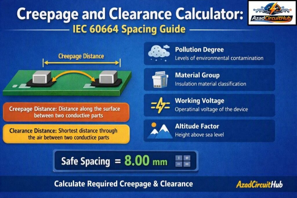
Table of Contents
Table of Contents
Quick Creepage and Clearance Calculator Reference Table
| Parameter | Meaning | Main Concern |
|---|---|---|
| Clearance | Shortest distance through air | Flashover and arcing |
| Creepage | Shortest distance along an insulating surface | Surface tracking |
| Working voltage | Voltage present during normal operation | Insulation stress |
| Rated impulse voltage | Expected transient overvoltage level | Short-duration breakdown |
| Pollution degree | Expected contamination around insulation | Surface leakage |
| Material group | CTI-based insulation classification | Creepage requirement |
| Altitude | Installation height above sea level | Reduced air insulation strength |
| Insulation type | Functional, basic, supplementary, reinforced | Required safety level |
Creepage vs Clearance
The difference between these two measurements is essential when designing electrical equipment.
| Feature | Creepage Distance | Clearance Distance |
|---|---|---|
| Measurement path | Along an insulating surface | Directly through air |
| Main failure mode | Tracking and surface leakage | Arc or flashover |
| Affected by material CTI | Yes | Generally no |
| Affected by pollution | Strongly | Yes, depending on conditions |
| Affected by altitude | Indirectly/depending on application | Strongly |
| Typical application | PCB and terminal insulation | Air gaps between conductors |
| Primary standard reference | IEC 60664-1 | IEC 60664-1 |
For example, if two PCB traces are separated by an insulating board, the clearance is measured directly across the air gap. The creepage distance follows the surface of the PCB between the two conductive traces.
A reliable Creepage and Clearance Calculator must therefore treat the two values separately instead of using one spacing value for both.
What Is a Clearance Distance?
Clearance is the shortest distance between two conductive parts measured through air. It is particularly important when dealing with high voltage because an electrical arc can jump across an air gap when the electric field becomes sufficiently strong.
Clearance requirements are primarily influenced by the voltage stress and transient conditions.
Important factors include:
- Rated impulse voltage
- Working voltage
- Overvoltage category
- Altitude
- Air pressure
- Insulation type
- Equipment application
For example, equipment exposed to higher transient overvoltages may require a greater clearance than equipment operating under relatively controlled electrical conditions.
This is why simply using a general voltage-to-distance rule can produce an unsafe design.
What Is a Creepage Distance?
Creepage is the shortest distance between two conductive parts measured along the surface of an insulating material.
Unlike clearance, creepage is strongly affected by the condition and characteristics of the insulating surface. Dust, moisture, chemicals, salt, and other contaminants can create a conductive path across the insulation.
The Creepage and Clearance Calculator should therefore consider the pollution degree and the comparative tracking index, commonly known as CTI, when determining creepage requirements.
Typical pollution categories include:
| Pollution Degree | General Description |
|---|---|
| PD 1 | No or only dry, non-conductive pollution |
| PD 2 | Normally non-conductive pollution; temporary condensation may occur |
| PD 3 | Conductive pollution or dry pollution becoming conductive due to condensation |
| PD 4 | Persistent conductive pollution, including conductive dust or rain |
The actual classification should be selected according to the installation environment and applicable product standard.
IEC 60664 Creepage and Clearance Factors
IEC 60664-1 does not provide one universal spacing for every voltage. The required distance must be selected based on the applicable design conditions.
A typical calculation process considers:
- Determine the working voltage.
- Identify the insulation system.
- Determine the required rated impulse voltage.
- Establish the overvoltage category.
- Select the pollution degree.
- Determine the insulating material group using CTI.
- Check altitude requirements.
- Select the applicable IEC 60664 tables.
- Compare the calculated spacing with product-specific requirements.
- Apply the greater value where another applicable standard requires it.
For a deeper reference, see our guide to Clearance and Creepage Distance as per IEC 60664 for detailed IEC spacing tables and selection criteria.
Creepage Distance and Material Group
The CTI of an insulating material is important when establishing creepage distance.
The material is commonly classified into groups based on its comparative tracking index:
| Material Group | CTI Range |
|---|---|
| Group I | CTI ≥ 600 |
| Group II | 400 ≤ CTI < 600 |
| Group IIIa | 175 ≤ CTI < 400 |
| Group IIIb | 100 ≤ CTI < 175 |
Materials with better resistance to tracking can generally support smaller creepage distances under the same conditions.
However, CTI alone does not determine the final spacing. Working voltage, pollution degree, insulation type, and the applicable standard tables must also be considered.
Working Voltage and Insulation Type
The required spacing changes according to the purpose of the insulation.
Common insulation categories include:
| Insulation | Purpose |
|---|---|
| Functional insulation | Required only for proper equipment operation |
| Basic insulation | Provides basic protection against electric shock |
| Supplementary insulation | Additional protection if basic insulation fails |
| Double insulation | Combination of basic and supplementary insulation |
| Reinforced insulation | Single insulation system providing equivalent protection to double insulation |
A safety-critical design should never assume that functional insulation provides the same protection as reinforced insulation.
When using a Creepage and Clearance Calculator, identify the insulation level before selecting the final spacing.
Example | Creepage and Clearance Calculator
Consider a 230 V AC control board using an insulating material with Material Group IIIa. Assume the equipment is designed for pollution degree 2, with an overvoltage category of III.
| Parameter | Example Value |
|---|---|
| Working voltage | 230 V AC |
| Rated insulation voltage | 250 V |
| Pollution degree | 2 |
| Overvoltage category | III |
| Material group | IIIa |
| Insulation | Basic insulation |
| Standard | IEC 60664-1 |
1. Clearance Calculation
Clearance is the shortest distance through air between two conductive parts.
For this example, assume the applicable IEC 60664-1 table gives a required clearance of approximately:
Clearance = 3.0 mm
Therefore:
Provided clearance ≥ Required clearance
If the PCB layout provides 3.5 mm:
3.5 mm ≥ 3.0 mm → Pass
2. Creepage Calculation
Creepage is the shortest distance along the surface of the insulating material between two conductive parts.
For 230 V AC, Pollution Degree 2, Material Group IIIa, assume the applicable IEC 60664-1 creepage requirement is:
Required creepage = 2.5 mm
If the PCB provides a surface path of 4.0 mm:
4.0 mm ≥ 2.5 mm → Pass
Creepage vs. Clearance Result
| Check | Required | Provided | Result |
|---|---|---|---|
| Clearance | 3.0 mm | 3.5 mm | Pass |
| Creepage | 2.5 mm | 4.0 mm | Pass |
Key point: Creepage and clearance must be evaluated separately. A PCB can have sufficient air clearance but still fail the creepage requirement if the surface path is too short.
PCB Creepage and Clearance
PCB design is one of the most common applications for insulation spacing calculations.
Designers should check spacing between:
- Line and neutral
- Line and protective earth
- Primary and secondary circuits
- High-voltage traces
- Transformer pins
- Optocoupler pins
- Connector terminals
- Relay contacts
- Heat sinks
- Mounting hardware
Solder mask should not automatically be treated as a substitute for the required insulation distance. The design should follow the applicable standard and product-specific requirements.
For high-voltage PCBs, slots and barriers can sometimes increase creepage distance while maintaining a compact board size.
For more detailed spacing references, use our complete guide to Clearance and Creepage Distance as per IEC 60664 when checking PCB, power supply, and control circuit designs.
Creepage and Clearance for Common Voltage Levels
The following table provides general design context rather than universal minimum values.
| Voltage Level | Typical Design Application | Spacing Must Be Based On |
|---|---|---|
| 12 V DC | Control electronics | Application and insulation requirement |
| 24 V DC | Industrial controls | Working voltage and environment |
| 48 V DC | Telecom and low-voltage power | Working voltage and pollution |
| 120 V AC | Residential electronics | IEC/product standard requirements |
| 230 V AC | Single-phase equipment | Working voltage, transient level, PD and material |
| 400 V AC | Three-phase equipment | Insulation system and applicable IEC tables |
| 600 V AC | Industrial equipment | Rated impulse voltage and environmental conditions |
| 1000 V DC | Solar and power electronics | Application-specific insulation coordination |
These voltage levels should not be used as standalone spacing rules. The applicable standard, equipment category, environment, and insulation system determine the final value.
Altitude and Clearance
Altitude can become important for high-voltage equipment installed at elevated locations.
As altitude increases, air density decreases. This reduces the dielectric strength of air and can increase the risk of electrical breakdown across a given air gap.
Therefore, a clearance suitable at sea level may not provide the same level of protection at a significantly higher elevation.
An engineering design using a Creepage and Clearance Calculator should include altitude whenever the applicable standard requires an altitude correction.
How to Increase Creepage Distance
When a PCB or electrical assembly does not have enough surface distance, designers can consider several layout techniques.
Add a PCB Slot
A properly designed slot can force the electrical path to travel around the opening, increasing creepage distance.
Increase Terminal Spacing
Increasing the physical separation between terminals can improve both creepage and clearance.
Add Insulating Barriers
An insulating barrier can separate primary and secondary circuits and help maintain the required insulation system.
Use Surface Grooves
Grooves or molded features can increase the surface path between conductive parts.
Relocate Conductive Hardware
Screws, brackets, heat sinks, shields, and mounting hardware should be reviewed because they can unintentionally reduce the effective spacing.
Common Mistakes in Creepage and Clearance Design
Several errors repeatedly appear in electrical and PCB designs.
- Treating creepage and clearance as the same measurement
- Using voltage alone to determine spacing
- Ignoring pollution degree
- Selecting the wrong material group
- Forgetting transient overvoltage
- Ignoring altitude
- Assuming solder mask provides unlimited protection
- Measuring around an incorrect physical path
- Ignoring screws and metal mounting hardware
- Using generic spacing charts instead of the applicable product standard
These mistakes can lead to insulation failure, excessive leakage current, tracking, or arcing.
Before finalizing a design, compare the calculated values with the relevant equipment standard because product-specific standards can impose additional or different requirements.
Creepage and Clearance Design Checklist
| Check | Required Action |
|---|---|
| Working voltage | Determine normal operating voltage |
| Transient voltage | Establish rated impulse voltage |
| Overvoltage category | Select the correct category |
| Pollution degree | Assess installation environment |
| CTI | Determine insulating material group |
| Insulation | Identify functional, basic, supplementary, or reinforced |
| Altitude | Apply correction where required |
| PCB layout | Verify actual physical paths |
| Barriers | Check slots, grooves, and insulation barriers |
| Final verification | Compare against applicable product standard |
For engineers working with different IEC voltage systems, our reference on Clearance and Creepage Distance as per IEC 60664 can be used alongside the calculator to verify the applicable design criteria.
Why a Calculator Is Useful
A Creepage and Clearance Calculator makes the insulation coordination process easier by bringing the major input parameters together.
Instead of selecting a spacing from a generic voltage chart, the designer can evaluate the actual application conditions. This is especially useful for switchgear, control panels, power supplies, inverters, EV chargers, industrial automation equipment, solar equipment, and PCBs.
The important point is that a calculator should support engineering judgment rather than replace the applicable standard.
Final Takeaway
A Creepage and Clearance Calculator is a practical design tool for determining electrical insulation spacing, but the result depends on more than voltage alone. Clearance protects against breakdown through air, while creepage controls the risk of surface tracking across an insulating material.
IEC 60664-1 provides the framework for insulation coordination, including working voltage, transient conditions, pollution degree, material characteristics, and altitude.
For safety-critical equipment, always verify the calculated spacing against the latest applicable IEC standard and the product-specific requirements before releasing a design for manufacture.
FAQs
What is the difference between creepage and clearance?
Clearance is the shortest distance through air between two conductive parts. Creepage is the shortest distance along the surface of an insulating material. Both are important for preventing electrical insulation failure.
How is creepage distance calculated?
Creepage is selected using factors such as working voltage, pollution degree, insulating material group, and insulation type. IEC 60664-1 provides the relevant criteria and tables for insulation coordination.
How is clearance distance calculated?
Clearance depends mainly on the required insulation level, rated impulse voltage, transient conditions, overvoltage category, and altitude. The applicable IEC 60664 requirements should be used rather than relying on voltage alone.
Does PCB solder mask count as creepage distance?
Solder mask should not automatically be assumed to provide the same insulation performance as the base insulating material. Whether it can be considered depends on the applicable standard, construction, and product requirements.
Why does pollution degree affect creepage?
Dust, moisture, chemicals, and other contaminants can make an insulating surface partially conductive. Higher pollution levels can therefore require greater creepage distances to reduce the risk of surface tracking.
Related Guides & Tools
- Clearance and Creepage Distance as per IEC 60664
- Phase to Phase Clearance Calculator
- IEC Standard for Creepage Distance
Get new guides in your feed. Follow Electrical Insights on LinkedIn for new electrical standards guides, calculators and design tips from Azad Circuit Hub.
#CreepageAndClearance, #IEC60664, #ClearanceCalculator, #CreepageCalculator, #ElectricalSafety, #PCBDesign, #InsulationCoordination, #ElectricalEngineering, #VoltageClearance, #IECStandards
Creepage and Clearance Calculator: IEC 60664 Spacing Guide
Creepage and Clearance Calculator based on IEC 60664. Calculate electrical spacing requirements for voltage, pollution degree, insulation, and safety.
Price Currency: USD
Operating System: All
Application Category: UtilitiesApplication
