
Ground Fault Protection vs Earth Leakage Protection
Ground fault protection and earth leakage protection are both designed to detect unwanted current flowing to earth, but they are not always used for the same purpose. Understanding the difference is important when selecting protective relays, residual current devices, circuit breakers, and electrical protection settings.
| Feature | Ground Fault Protection | Earth Leakage Protection |
|---|---|---|
| Primary purpose | Protect equipment and systems from ground faults | Detect current leaking to earth |
| Typical fault level | Medium to high | Low to medium |
| Main concern | Equipment damage, fire and fault clearing | Shock protection and insulation leakage |
| Common devices | Ground fault relay, breaker trip unit | RCCB, RCD, earth leakage relay |
| Typical sensitivity | Higher pickup current | Lower pickup current |
| Application | Industrial and commercial systems | Residential, commercial and industrial |
| Detection method | Residual or zero-sequence current | Residual current through a core balance CT |
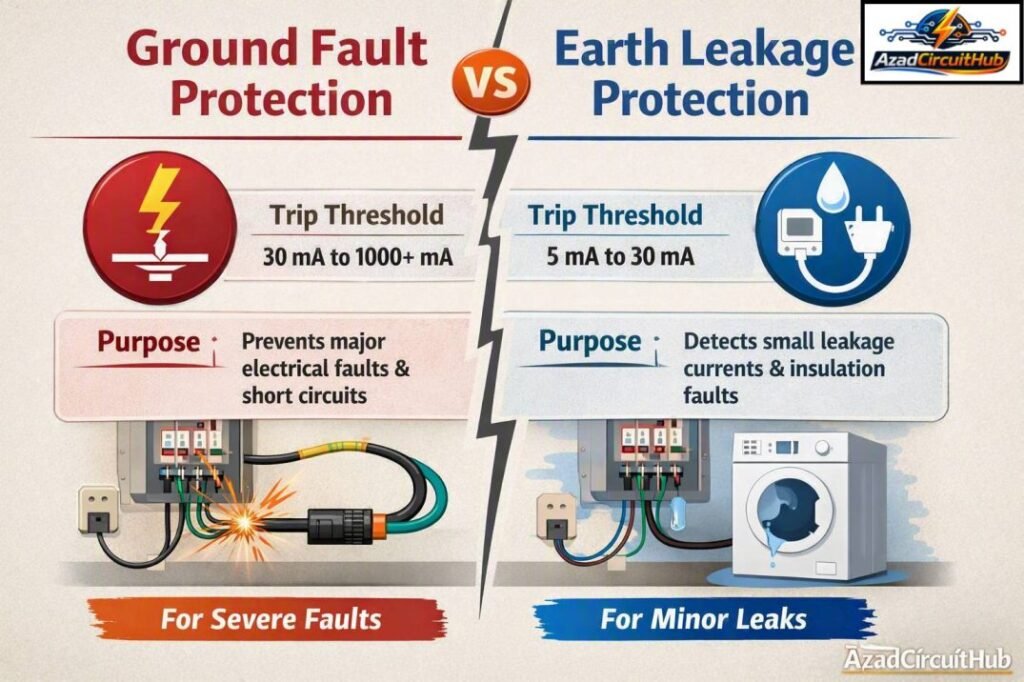
Table of Contents
Table of Contents
What Is Ground Fault Protection?
Ground fault protection is a protective function that detects current flowing from an energized conductor to ground through an unintended path. The fault can occur because of damaged insulation, moisture, contamination, mechanical damage, or equipment failure.
In a three-phase system, a ground fault may involve one phase and earth, while more severe faults can involve two or three phases. The protection system measures the imbalance between phase currents and identifies a residual current that should not normally exist.
A ground fault relay can then send a trip signal to the circuit breaker. The objective is to limit thermal damage, reduce fire risk, protect electrical equipment, and isolate the faulty section quickly.
Ground fault protection is especially important in:
- Industrial distribution systems
- Motor control centers
- Transformers
- Switchgear
- Generators
- Large commercial buildings
- Solar power systems
- Data centers
The protection setting depends on the system design, equipment rating, grounding arrangement, and coordination requirements.
What Is Earth Leakage Protection?
Earth leakage protection monitors unwanted current escaping from an electrical circuit to earth. Unlike a normal load current, leakage current does not return through the intended circuit conductors.
An earth leakage relay normally uses a core balance current transformer, also called a zero-sequence CT. All live conductors pass through the sensing core. Under normal conditions, the vector sum of the currents is close to zero.
When some current flows to earth, the current balance changes. The sensing device detects this residual current and operates when it exceeds the configured threshold.
Earth leakage protection is widely used where relatively small leakage currents must be detected before they become dangerous.
| Protection type | Typical objective | Common application |
|---|---|---|
| Ground fault protection | Clear damaging ground faults | Industrial switchgear |
| Earth leakage protection | Detect insulation leakage | Distribution circuits |
| RCD/RCCB | Protect against residual current | Homes and commercial buildings |
| Earth fault relay | Detect earth faults | Transformers and feeders |
| Ground fault trip | Disconnect faulty circuit | Circuit breakers |
Ground Fault Protection vs Earth Leakage Protection: Main Differences
The key difference between these two functions is usually the level of current they are intended to detect and the protection objective.
Ground fault protection is generally associated with fault currents that can become large enough to damage conductors, transformers, motors, switchgear, or other equipment. Earth leakage protection often operates at lower current levels and is commonly selected for personal protection or early detection of insulation problems.
However, the terms can overlap. In many electrical systems, manufacturers and engineers use ground fault, earth fault, earth leakage, residual current, and ground leakage in slightly different ways.
| Parameter | Ground Fault Protection | Earth Leakage Protection |
|---|---|---|
| Fault current | Usually higher | Usually lower |
| Protection goal | Equipment and system protection | Leakage and shock protection |
| Sensitivity | Relatively lower | Relatively higher |
| CT arrangement | Residual CT or phase CTs | Usually CBCT |
| Trip time | Selected for coordination | Often fast |
| Main standard considerations | NEC, IEEE, IEC | IEC, local wiring regulations |
| Typical device | Protective relay/breaker | RCD/RCCB/ELR |
How Does the Detection Method Work?
Both protection methods can rely on residual current measurement.
For a balanced three-phase system:
Iₐ + Iᵦ + I꜀ = 0
If a portion of current flows through an unintended earth path, the vector sum is no longer zero.
For example, if a feeder has 100 A flowing in each phase under balanced conditions, the residual current is theoretically zero. If 5 A escapes through the equipment grounding path, the sensing system detects approximately 5 A of residual current.
A core balance CT provides a practical method for measuring this current. The CT surrounds all phase conductors and, where applicable, the neutral conductor. The protective relay evaluates the resulting secondary signal.
Ground Fault Protection vs Earth Leakage Protection Settings
Protection settings must be selected carefully. A setting that is too low can cause nuisance tripping, while a setting that is too high may fail to provide adequate protection.
Important settings include pickup current and operating time.
| Setting | Purpose | Effect of incorrect setting |
|---|---|---|
| Pickup current | Defines when protection operates | Nuisance trips or poor fault protection |
| Time delay | Controls operating time | Poor selectivity |
| Instantaneous trip | Clears severe faults rapidly | Unwanted operation if poorly coordinated |
| CT ratio | Scales measured current | Incorrect relay operation |
| Reset mode | Defines relay recovery | Operational issues |
For engineers working with protective relays, an accurate earth fault relay setting calculation helps determine suitable pickup values and time delays while maintaining coordination with upstream and downstream devices.
Why Selectivity Matters
Electrical protection should not simply disconnect the largest possible section of the system. Ideally, the protective device nearest to the fault should operate first.
This principle is known as selectivity or discrimination.
For example, if an earth fault occurs on a motor feeder, the motor feeder breaker should normally trip before the main switchboard breaker. This keeps the rest of the facility energized.
Ground fault relay settings therefore need to consider:
- Downstream protective devices
- Transformer impedance
- Available short-circuit current
- Cable ampacity
- Grounding method
- CT characteristics
- Relay operating time
- Equipment withstand ratings
Ground Fault Protection vs Earth Leakage Protection in Different Systems
The best protection method depends on the application.
| System | Recommended protection approach |
|---|---|
| Residential final circuit | RCD/RCCB or RCBO |
| Industrial motor feeder | Ground/earth fault relay |
| Transformer secondary | Ground fault protection |
| Generator | Ground fault or restricted earth fault protection |
| Solar inverter output | Residual current monitoring and appropriate ground fault protection |
| Large commercial distribution | Ground fault relay and breaker protection |
| Portable equipment | RCD/GFCI-type protection where required |
In a residential circuit, a sensitive residual current device may be appropriate because the primary concern can be protection against electric shock.
In a large industrial feeder, however, protection must also consider conductor heating, equipment damage, fault clearing, and coordination with other relays.
Common Causes of Earth Leakage
Earth leakage does not always indicate a major fault. Some equipment naturally produces small leakage currents because of filters, capacitors, variable frequency drives, power supplies, and long cables.
Common causes include:
- Damaged cable insulation
- Moisture inside equipment
- Contaminated switchgear
- Aging motor insulation
- Variable frequency drives
- EMI filter capacitors
- Long cable runs
- Incorrect wiring
- Damaged appliances
- Poor insulation resistance
This is why protection settings should account for the normal leakage current of the system.
Ground Fault Protection vs Earth Leakage Protection for Equipment Safety
Both methods improve electrical safety, but their roles should not be confused.
Ground fault protection is often coordinated with circuit breakers to clear faults that could produce substantial thermal and mechanical stress. Earth leakage protection can detect smaller current paths that may indicate deteriorating insulation or a dangerous leakage condition.
The correct choice depends on the electrical system and applicable code.
A protection study should evaluate fault current, normal leakage, grounding configuration, equipment ratings, and required clearing time before finalizing settings.
For related relay protection work, use an earth fault relay setting calculation to estimate suitable relay pickup and time parameters before applying settings to an actual protection system.
Testing and Maintenance
Protection devices should be tested regularly according to the manufacturer’s instructions and the applicable electrical safety standard.
A typical inspection may include:
- Visual inspection of wiring
- CT connection verification
- Relay functional testing
- Secondary injection testing
- Trip circuit testing
- Breaker trip verification
- Insulation resistance testing
- Verification of relay settings
- Review of event records
For an earth leakage relay, the test should confirm that the device detects the intended residual current and operates within the specified tolerance.
For ground fault protection, testing should also verify coordination between the relay and circuit breaker.
Ground Fault Protection vs Earth Leakage Protection: Which One Should You Use?
There is no universal answer. The appropriate protection depends on the system voltage, grounding arrangement, fault current, load type, equipment ratings, local regulations, and required protection level.
Use sensitive residual current protection where low-level leakage and personnel safety are key concerns. Use coordinated ground fault protection where larger faults could damage equipment or interrupt an industrial power system.
In many installations, both approaches may be used together. A commercial or industrial facility can have sensitive residual current protection on selected circuits while using coordinated ground fault protection at major distribution levels.
| Requirement | Suitable protection |
|---|---|
| Personnel shock protection | RCD/RCCB/RCBO |
| Small leakage detection | Earth leakage relay |
| Large equipment fault protection | Ground fault relay |
| Feeder protection | Ground/earth fault protection |
| Early insulation fault detection | Sensitive residual current protection |
| System-wide coordination | Protection relay with time grading |
Final Takeaway
Ground fault protection and earth leakage protection serve related but distinct purposes. Ground fault protection generally focuses on clearing damaging faults and protecting electrical equipment, while earth leakage protection is commonly used to detect lower-level residual current and improve electrical safety.
The terms can overlap depending on the manufacturer, electrical code, and application. For this reason, engineers should look beyond the terminology and examine the relay sensitivity, CT arrangement, operating time, grounding system, and intended protection function.
Proper coordination is equally important. A correctly selected pickup value and time delay can prevent nuisance trips while ensuring that dangerous faults are cleared quickly. A reliable earth fault relay setting calculation is therefore an important part of designing and commissioning an effective protection system.
FAQs
Is ground fault protection the same as earth leakage protection?
Not always. Both can detect residual current flowing to earth, but ground fault protection is commonly designed for equipment and system fault protection, while earth leakage protection often focuses on detecting lower-level leakage current.
What is the difference between a ground fault and earth leakage?
A ground fault generally refers to an unintended connection between an energized conductor and earth. Earth leakage refers to current escaping from its intended circuit path to earth. A leakage condition can be an early indication of insulation deterioration.
Does an earth leakage relay use a CT?
Yes. Most earth leakage relays use a core balance current transformer or zero-sequence CT. The live conductors pass through the CT, allowing the device to measure the residual current.
Can ground fault protection prevent electric shock?
It can reduce the risk associated with ground faults, but not every ground fault protection system is designed for personnel protection. Sensitive RCD, RCCB, RCBO, or GFCI-type protection may be required for shock protection depending on the installation and applicable regulations.
How do you set an earth fault relay?
The setting depends on the load current, fault level, grounding method, CT ratio, equipment ratings, normal leakage current, and coordination requirements. Pickup current and time delay should be selected through a protection study rather than using a universal value.
Get new guides in your feed. Follow Electrical Insights on LinkedIn for new electrical standards guides, calculators and design tips from Azad Circuit Hub.
#GroundFaultProtection, #EarthLeakageProtection, #GroundFault, #EarthLeakage, #ElectricalProtection, #GroundFaultRelay, #EarthLeakageRelay, #ElectricalSafety, #FaultProtection, #ElectricalEngineering

Excellent approach to explaining this.