
Medium & High Voltage Cable Bending Radius: 33kV, 66kV, 132kV & EHV Guide
High voltage cable installation requires more care than simply checking whether a cable can physically make a turn. The minimum radius affects the conductor, insulation, metallic screen, sheath, water-blocking layers and overall cable life. This is why the High Voltage Cable Bending Radius should always be checked against the cable manufacturer’s installation data before pulling or terminating a cable.
For medium- and high-voltage systems, the permitted radius depends on cable construction, voltage class, conductor size, insulation type, screen design, sheath and whether the cable is being bent during installation or after it has been installed. A commonly used rule of thumb is around 15 to 20 times the overall cable diameter for some HV cables, but this is not a universal design value.
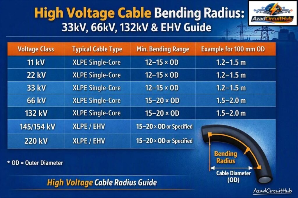
Table of Contents
Table of Contents
High Voltage Cable Bending Radius Chart
The table below provides practical starting values. Always use the manufacturer’s datasheet where it gives a different minimum radius.
| Voltage Class | Typical Cable Type | Common Minimum Bending Range* | Example for 100 mm OD |
|---|---|---|---|
| 11 kV | XLPE single-core | 12–15 × OD | 1.2–1.5 m |
| 22 kV | XLPE single-core | 12–15 × OD | 1.2–1.5 m |
| 33 kV | XLPE single-core | 12–15 × OD | 1.2–1.5 m |
| 66 kV | XLPE single-core | 15–20 × OD | 1.5–2.0 m |
| 132 kV | XLPE single-core | 15–20 × OD | 1.5–2.0 m |
| 145/154 kV | XLPE/EHV | 15–20 × OD or manufacturer value | 1.5–2.0 m |
| 220 kV | XLPE/EHV | 15–20 × OD or manufacturer value | 1.5–2.0 m |
*Indicative engineering ranges only. The cable manufacturer’s specified minimum installation and operating bend radii take precedence.
For example, if a 33 kV cable has an outside diameter of 80 mm and the specified minimum radius is 15 × OD:
Minimum radius = 15 × 80 = 1,200 mm = 1.2 m
The radius is measured from the cable centerline, not from the inside edge of the bend.
For quick and accurate cable routing checks, use our cable bending radius calculator to determine the recommended bend radius for different cable sizes and constructions.
What Is High Voltage Cable Bending Radius?
High Voltage Cable Bending Radius is the smallest radius to which a cable can safely be bent without causing mechanical or electrical damage. A smaller radius produces greater mechanical strain in the cable layers.
The requirement is especially important for XLPE insulated cables because excessive bending can affect the insulation screen, conductor screen, metallic sheath and other components.
Two values should be distinguished:
| Bend condition | Meaning |
|---|---|
| Installation bending radius | Minimum radius allowed while pulling and positioning the cable |
| Final installed radius | Minimum radius permitted after the cable is permanently positioned |
| Temporary bend | Radius used briefly during handling or pulling |
| Termination bend | Radius required near stress cones and cable accessories |
| Manufacturer’s minimum radius | The controlling value for that specific cable |
Never assume that a cable with a large diameter can tolerate the same bending ratio as a smaller cable.
Medium Voltage Cable Bending Radius
Medium voltage cable bending radius requirements vary considerably with cable construction. Typical MV cables from 6.6 kV to 35 kV may use XLPE insulation, copper or aluminium conductors, copper wire screens and PE or PVC outer sheaths.
For a typical single-core XLPE cable, the minimum radius may be specified as a multiple of the overall diameter.
| MV Cable | Typical reference range |
|---|---|
| 6.6 kV | 12–15 × OD |
| 11 kV | 12–15 × OD |
| 22 kV | 12–15 × OD |
| 33 kV | 12–15 × OD |
| Armoured MV cable | Often higher than unarmoured construction |
The actual value should be taken from the manufacturer’s technical specification.
A cable route should therefore be designed with enough space for the specified radius rather than designing the trench or duct first and trying to force the cable into place later.
For a broader explanation of international cable installation requirements, see our guide to cable bending radius iec standard and cable installation practices.
33kV Cable Bending Radius
The 33kv cable bending radius is commonly expressed as a multiple of the cable’s overall diameter. Many 33 kV XLPE cables use values in the range of 12 to 15 times OD, while some constructions require a larger radius.
For example:
| 33 kV Cable OD | 12 × OD | 15 × OD | 20 × OD |
|---|---|---|---|
| 60 mm | 720 mm | 900 mm | 1,200 mm |
| 70 mm | 840 mm | 1,050 mm | 1,400 mm |
| 80 mm | 960 mm | 1,200 mm | 1,600 mm |
| 90 mm | 1,080 mm | 1,350 mm | 1,800 mm |
| 100 mm | 1,200 mm | 1,500 mm | 2,000 mm |
A 33 kV cable should not automatically be bent to 12 × OD simply because another manufacturer’s cable has the same voltage rating. Conductor size, screen arrangement, insulation thickness and sheath construction can change the permitted value.
Planning a cable installation? Our cable bending radius calculator makes it easy to estimate the minimum bending radius before routing power and control cables.
66kV Cable Bend Radius
The 66kv cable bend radius is particularly important during installation because these cables are normally larger, heavier and mechanically more demanding than standard MV cables.
A 66 kV XLPE cable may have a manufacturer’s minimum bending radius around 15 to 20 times its overall diameter. Some cable designs can have different requirements.
Suppose a 66 kV cable has an OD of 110 mm and the specified radius is 20 × OD:
Minimum bend radius = 20 × 110 = 2,200 mm
This means the centerline radius should not be less than 2.2 m.
Cable rollers, bell mouths and pulling equipment should be positioned so the cable never approaches a sharp edge during installation.
Is the 20 × OD Rule Always Correct?
The often-quoted HV cable bend radius rule of thumb 20x OD is useful as a conservative preliminary design reference, but it is not a substitute for the manufacturer’s requirement.
For example, a 20 × OD radius for a 120 mm cable gives:
20 × 120 = 2,400 mm
However, the cable manufacturer may specify 15 × OD, 18 × OD, 20 × OD or another value based on its construction.
The correct hierarchy is:
- Cable manufacturer’s installation specification
- Project specification
- Applicable cable and installation standards
- Engineering practice or preliminary rule of thumb
This distinction is important for tendering, trench design and cable pulling calculations.
Shielded High Voltage Cable Bend Radius
A shielded high voltage cable contains additional metallic layers around the insulation system. Depending on the design, this may include copper wire screens, copper tape screens, concentric conductors, lead sheaths or aluminium metallic barriers.
These layers can influence the mechanical behavior of the cable.
During bending, engineers should consider:
- XLPE insulation
- Conductor screen
- Insulation screen
- Copper wire or tape screen
- Metallic sheath
- Water-blocking components
- Outer sheath
- Armour, where applicable
A sharp bend can place excessive strain on the metallic screen or sheath even when the outer jacket appears undamaged.
Bending Radius of Cables in Trefoil Formation
For three single-core cables installed in trefoil, each cable must satisfy its own minimum bending radius. The complete trefoil arrangement also needs sufficient space to transition around bends.
The cables should not be forced into a common sharp curve simply to maintain trefoil geometry.
| Installation point | Main consideration |
|---|---|
| Straight trefoil run | Maintain designed cable spacing |
| Horizontal bend | Check each cable’s radius |
| Vertical bend | Check support and cable weight |
| Transition to termination | Follow accessory manufacturer’s requirements |
| Cleats | Prevent excessive movement without crushing cables |
At high voltage, trefoil cleating also has to withstand prospective short-circuit forces. Bend radius and cleat spacing should therefore be considered together.
For more cable installation calculations and practical examples, our detailed cable bending radius guide covers the relationship between cable diameter, bend radius and installation conditions.
Bending Radius in Quad Formation
Four single-core cables are often arranged in quad or square formation for certain high-current circuits. The formation itself does not eliminate the minimum radius requirement.
Each individual cable must remain within its permitted bending radius while the group transitions through the bend.
The cable support system should prevent one cable from taking a tighter radius than the others. This is particularly important where cables enter switchgear, transformers, GIS equipment or cable sealing ends.
132kV Cable Bend Radius
A 132kV cable bend radius is normally considerably larger in absolute terms because 132 kV cables have larger overall diameters and more complex insulation systems.
For a 132 kV cable with an OD of 125 mm:
| Bend factor | Radius |
|---|---|
| 15 × OD | 1.875 m |
| 18 × OD | 2.250 m |
| 20 × OD | 2.500 m |
The selected value must match the manufacturer’s data.
132 kV cable systems often involve long underground routes, vertical sections, joints and sealing ends. The route should therefore be checked before procurement so that the cable drum, pulling equipment, trench geometry and joint-bay dimensions are compatible.
145kV, 154kV and 220kV Cable Bend Radius
For 145 kV, 154 kV and 220 kV systems, cable construction becomes increasingly important. These installations may use large single-core XLPE cables with metallic sheaths and sophisticated jointing systems.
A useful preliminary calculation is:
R = K × D
Where:
- R = minimum bend radius
- K = manufacturer’s bend-radius factor
- D = overall cable diameter
For example, for a 220 kV cable with a 150 mm OD and a specified factor of 20:
R = 20 × 150 = 3,000 mm
Therefore, the calculated minimum radius is 3 m.
The same calculation method can be used for 145 kV and 154 kV cables, but the value of K must come from the actual cable design.
Need to verify a cable bend before installation? Check our cable bending radius calculator for a practical way to calculate suitable bending requirements based on cable dimensions.
EHV Cable Bending Radius IEC Standard
There is no single IEC value that can be applied to every EHV cable simply from its voltage rating. IEC cable standards cover cable design, testing and other requirements, while the manufacturer’s installation instructions provide the specific mechanical limitations for a particular cable.
IEC 60840 is commonly associated with power cables and accessories for rated voltages above 30 kV up to and including 150 kV. IEC 62067 covers power cables and accessories above 150 kV up to and including 500 kV.
For EHV cable bending radius IEC standard requirements, the project should therefore consider the applicable IEC product standard together with the manufacturer’s cable data and installation procedure.
How to Calculate Cable Bend Radius
The calculation is straightforward when the cable diameter and manufacturer’s bend factor are known.
Formula:
Minimum bend radius = Bend factor × Overall cable diameter
Example:
Cable OD = 95 mm
Specified factor = 15
R = 15 × 95 = 1,425 mm
Therefore, the centerline radius should be at least 1.425 m.
The corresponding bend diameter is twice the radius:
Bend diameter = 2 × 1.425 = 2.85 m
This distinction is useful when designing cable pits, ducts and pulling routes.
If you are comparing different cable sizes, use the cable bend radius calculation method to check whether the planned trench or duct arrangement provides adequate clearance.
Installation Factors That Can Reduce Cable Life
A cable may pass a visual inspection after installation but still have suffered excessive mechanical stress. Common causes include:
- Pulling around undersized rollers
- Sharp trench corners
- Excessive sidewall pressure
- Incorrect winch setup
- Poor drum orientation
- Bending near joints
- Tight bends at switchgear entries
- Unsupported vertical cable sections
- Pulling multiple cables simultaneously without proper planning
The bending radius of cable should therefore be checked during cable pulling, not only after installation.
Cable Bend Radius Quick Reference
| Calculation | Result |
|---|---|
| 15 × 80 mm | 1.20 m |
| 15 × 100 mm | 1.50 m |
| 18 × 100 mm | 1.80 m |
| 20 × 100 mm | 2.00 m |
| 20 × 125 mm | 2.50 m |
| 20 × 150 mm | 3.00 m |
These figures are calculation examples rather than universal permissible values.
Frequently Asked Questions
What is the minimum bending radius for a high voltage cable?
The minimum radius depends on cable construction and the manufacturer’s specification. A value between 15 and 20 times the overall diameter is commonly encountered for many HV and EHV cables, but the approved cable datasheet should always control.
Is 20 times the cable diameter a safe bending radius?
20 × OD is a useful conservative rule of thumb for preliminary planning, but it is not a universal requirement. Some cables permit smaller radii, while others require larger radii because of their construction.
What is the bending radius of a 33 kV cable?
Many 33 kV XLPE cables have a minimum radius around 12–15 × OD, depending on design. For an 80 mm cable at 15 × OD, the minimum radius would be 1.2 m.
Can high voltage cables be bent after installation?
They can be bent within the limits specified by the manufacturer. However, unnecessary movement should be avoided, especially near joints, terminations and stress-control components.
Does cable diameter affect bending radius?
Yes. When the requirement is expressed as a multiple of OD, a larger cable directly produces a larger minimum radius. Cable construction can also change the multiplier, so diameter alone is not enough to determine the final value.
Final Design Check
High Voltage Cable Bending Radius should be treated as a critical installation parameter rather than a simple rule-of-thumb calculation. For 33 kV and 66 kV systems, the manufacturer’s installation radius should be checked before cable pulling. For 132 kV, 145 kV, 154 kV and 220 kV systems, route geometry, pulling tension, sidewall pressure, trefoil or quad formation, joints and terminations require even closer attention.
Before approving a cable route, confirm the cable OD, minimum installation radius, final installed radius, pulling tension, sidewall pressure and manufacturer’s installation procedure. This approach reduces mechanical damage and helps protect the long-term reliability of the high-voltage cable system.
Related Guides & Tools
- HV cable bending radius calculator
- Cable Bending Radius Chart by Cable Size
- Cable Bending Radius Rule of Thumb
- Cable Bending Radius Calculator
Get new guides in your feed. Follow Electrical Insights on LinkedIn for new electrical standards guides, calculators and design tips from Azad Circuit Hub.
#HighVoltageCable, #CableBendingRadius, #33kVCable, #66kVCable, #132kVCable, #EHVCable, #PowerCables, #CableInstallation, #ElectricalEngineering, #CableSizing
