
Cable Bending Radius Chart by Cable Size (mm² to AWG/kcmil)
A proper Cable Bending Radius Chart by Cable Size helps electricians, cable installers, engineers, and contractors determine how tightly a power or control cable can be routed without damaging its insulation, conductor, screen, sheath, or other internal layers.
Cable bending radius is normally expressed as a multiple of the cable’s overall outside diameter (OD). For example, a requirement of 12 × D means the minimum bending radius is 12 times the finished cable diameter. The required value can change with cable construction, voltage rating, conductor material, insulation, number of cores, armouring, and whether the cable is being bent during installation or after installation.
Cable Bending Radius Chart by Cable Size
The table below provides useful planning values for common cable sizes. These are typical ranges rather than universal limits.
| Cable Size | Approx. Equivalent | Typical Minimum Bend Radius* | Common Application |
|---|---|---|---|
| 20 AWG | 0.52 mm² | 4–8 × OD | Instrumentation/control |
| 26 AWG | 0.13 mm² | 3–6 × OD | Data/control |
| 28 AWG | 0.08 mm² | 3–6 × OD | Signal/data |
| 50 mm² 1C XLPE | 1/0 AWG approx. | 8–12 × OD | LV power |
| 95 mm² | 4/0 AWG approx. | 8–12 × OD | LV power |
| 185 mm² | 350 kcmil approx. | 10–15 × OD | LV/MV power |
| 240 mm² | 500 kcmil approx. | 10–15 × OD | LV/MV power |
| 300 kcmil | 152 mm² approx. | 10–15 × OD | Power distribution |
| 500 kcmil | 253 mm² approx. | 10–15 × OD | Large LV power |
| 600 kcmil | 304 mm² approx. | 10–15 × OD | Large LV power |
| 750 kcmil | 380 mm² approx. | 10–15 × OD | Large LV power |
| 630 mm² | 1267 kcmil approx. | 12–18 × OD | Large power cables |
| 1000 kcmil (1000 MCM) | 507 mm² approx. | 12–18 × OD | Large feeder systems |
*Typical planning ranges only. Manufacturer requirements and the applicable installation standard take priority.
For an exact installation, measure the cable’s actual outside diameter rather than calculating the radius from conductor cross-sectional area alone.
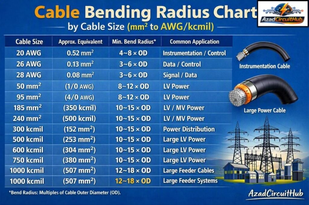
Table of Contents
Table of Contents
How to Calculate Cable Bending Radius
The basic calculation is simple:
Minimum bending radius = Cable outside diameter × Required radius factor
For example, assume a cable has an outside diameter of 32 mm and the manufacturer specifies a minimum radius of 12 × D.
32 × 12 = 384 mm minimum bending radius
This means the centerline of the cable should not be forced into a curve with a radius below 384 mm.
It is important to distinguish radius from diameter. A 384 mm bending radius produces a 768 mm diameter for the curved path. Confusing these two measurements is a common cable installation error.
A Cable Bending Radius Chart by Cable Size is therefore useful for preliminary design, but the final value should be based on the cable’s actual diameter and datasheet.
Cable Bending Radius by mm² Size
Metric conductor sizes are widely used with IEC-based cable systems. However, two cables with the same conductor area can have very different outside diameters.
| Cable Size | Typical Cable Type | Practical Radius Guidance |
|---|---|---|
| 50 mm² | Single-core XLPE | 8–12 × OD |
| 70 mm² | Single-core XLPE | 8–12 × OD |
| 95 mm² | XLPE power | 8–12 × OD |
| 120 mm² | XLPE power | 8–12 × OD |
| 150 mm² | XLPE power | 10–15 × OD |
| 185 mm² | XLPE power | 10–15 × OD |
| 240 mm² | XLPE power | 10–15 × OD |
| 300 mm² | XLPE power | 10–15 × OD |
| 400 mm² | XLPE power | 10–15 × OD |
| 500 mm² | XLPE power | 12–18 × OD |
| 630 mm² | XLPE power | 12–18 × OD |
For example, the bending radius of 240mm2 cable cannot be selected from the 240 mm² conductor area alone. If one manufacturer’s 240 mm² cable is 30 mm in diameter and another is 36 mm, the resulting minimum radii will be different even when the conductor size is identical.
For a broader discussion of installation requirements, see our guide to cable bending radius iec standard, which explains how cable construction and installation conditions affect the selected radius.
Single-Core and Multicore Cable Bend Radius
Single-core cables can behave differently from multicore cables because their construction, diameter, screen arrangement, and installation configuration are different.
A single-core 500 sqmm bending radius chart should therefore not be applied blindly to a three-core 500 mm² cable.
| Cable Construction | Typical Consideration |
|---|---|
| Single-core unarmoured | Often easier to route |
| Single-core XLPE | Check manufacturer’s radius factor |
| Multicore XLPE | Larger overall diameter can increase radius |
| Armoured cable | Armour may limit tight bending |
| Shielded/screened cable | Screen construction must be protected |
| MV cable | Strict attention to manufacturer radius |
| HV cable | Specialized installation requirements |
When installing parallel single-core cables, the individual cable radius and the complete routing arrangement should both be considered. Avoid forcing cables into a sharp turn simply to fit a termination cabinet.
95mm², 185mm² and 630mm² Cable Bend Radius
Large conductors require careful routing because their overall cable diameter can become substantial.
| Cable Size | Approx. AWG/kcmil Equivalent | Typical Radius Factor |
|---|---|---|
| 95 mm² | 4/0 AWG | 8–12 × OD |
| 185 mm² | 350–400 kcmil range | 10–15 × OD |
| 630 mm² | About 1250–1300 kcmil | 12–18 × OD |
The 95mm2 cable bend radius is normally much easier to accommodate than the radius required by a 630 mm² cable. Large cables may require wider trenches, larger bends, suitable rollers, and additional pulling equipment.
Always check whether the manufacturer’s value applies to installation bending radius, fixed bending radius, or another specified condition.
500/600/750 kcmil Bend Radius
American cable specifications commonly use AWG and kcmil. One kcmil represents a conductor area of 1,000 circular mils.
| Conductor Size | Approx. mm² | Typical Planning Radius |
|---|---|---|
| 300 kcmil | 152 mm² | 10–15 × OD |
| 500 kcmil | 253 mm² | 10–15 × OD |
| 600 kcmil | 304 mm² | 10–15 × OD |
| 750 kcmil | 380 mm² | 10–15 × OD |
| 1000 kcmil | 507 mm² | 12–18 × OD |
The bending radius of 300kcmil cable depends on the complete cable diameter, not simply the conductor size. A compact single-conductor design can have a different radius requirement from an armoured or screened construction.
The same principle applies to 500/600/750 kcmil bend radius calculations. Use the manufacturer’s outside diameter and specified radius factor for the particular cable.
Bending Radius of 50 mm² XLPE Cable
A minimum bending radius 1c 50 sq mm XLPE cable can often be estimated using the manufacturer’s stated multiple of cable diameter.
For example, if a particular 50 mm² single-core XLPE cable has a 14 mm outside diameter and its datasheet specifies 8 × D:
14 × 8 = 112 mm minimum radius
If the same cable requires 12 × D, the radius becomes:
14 × 12 = 168 mm
This example shows why conductor size alone is insufficient. Cable insulation thickness, voltage rating, conductor class, sheath, and screen can all change the finished diameter.
Small Cable Bend Radius: 20 AWG, 26 AWG and 28 AWG
Small control and signal cables often have much smaller bend radii than large power cables. However, flexible data cables can have special requirements.
| Size | Approx. Area | Typical Minimum Radius |
|---|---|---|
| 20 AWG | 0.52 mm² | 4–8 × OD |
| 26 AWG | 0.13 mm² | 3–6 × OD |
| 28 AWG | 0.08 mm² | 3–6 × OD |
For 20awg/26awg/28awg min bend radius requirements, the cable type is especially important. A shielded instrumentation cable, Ethernet cable, flexible control cable, and hook-up wire may all use similar conductor sizes but have different mechanical limits.
Avoid sharp kinks in small cables because repeated bending can damage insulation or alter the geometry of twisted-pair and shielded communication cables.
Bending Radius of 1000 MCM Cable
A 1000 MCM cable is approximately 507 mm² in conductor area. Because of its large size and mass, installation planning becomes increasingly important.
The bending radius of 1000mcm cable may commonly fall within a range around 12–18 × the cable outside diameter for preliminary planning, but this should never replace the manufacturer’s published requirement.
For example, if the actual cable diameter is 42 mm and the specified factor is 15 × D:
42 × 15 = 630 mm minimum radius
A cable this large may need properly sized rollers and carefully planned entry points at switchgear, transformers, cable trenches, and termination structures.
For a complete overview of calculation methods and installation factors, use our detailed cable bending radius guide before finalizing a cable route.
Installation Tips for Maintaining Cable Bend Radius
Good cable routing protects the cable and also makes future maintenance easier.
- Check the manufacturer’s datasheet before installation.
- Measure or obtain the actual cable outside diameter.
- Mark minimum-radius curves on drawings before cable pulling.
- Use cable rollers at changes in direction.
- Do not drag large cables around sharp corners.
- Avoid excessive pulling tension.
- Use correctly sized glands and termination accessories.
- Provide adequate space near switchgear and transformers.
- Consider both installation and final fixed-position radius.
- Inspect cables for kinks, sheath damage, or deformation after pulling.
For underground installations, trench geometry should be designed around the cable route rather than forcing a large cable into a small corner.
Cable Bending Radius vs Cable Size
It is tempting to assume that doubling conductor size doubles the required bending radius. In practice, that relationship is not linear.
The finished diameter is influenced by:
- conductor stranding;
- insulation thickness;
- metallic screen;
- armour;
- inner and outer sheaths;
- voltage class;
- number of cores;
- cable manufacturing design.
This is why a professional cable bend radius calculation starts with the actual cable construction instead of relying only on mm² or AWG.
For engineering documentation, record the cable manufacturer’s part number, outside diameter, minimum radius factor, installation condition, and applicable standard. This creates a clear design trail for contractors and inspectors.
What Standards Say About Cable Bending Radius
IEC cable standards and installation standards provide requirements that vary by cable type and application. IEC 60502 series cables, for example, cover important categories of power cables, while other standards address specific cable constructions and installation systems.
There is no single universal radius factor that applies to every cable covered by IEC standards.
Manufacturer data is therefore essential. The cable manufacturer may specify separate values for pulling, installation, fixed installation, or special conditions.
Where BS 7671, IEC requirements, NEC requirements, utility specifications, or project specifications apply, the installation should comply with the applicable requirements rather than using a generic chart.
Common Cable Bending Radius Mistakes
Several mistakes occur repeatedly on cable projects.
Using conductor area instead of outside diameter: A 240 mm² conductor does not automatically have one fixed cable diameter.
Confusing radius with diameter: A 300 mm radius is not the same as a 300 mm bend diameter.
Ignoring cable construction: Armoured, screened, multicore, and single-core cables can have different requirements.
Using the fixed radius during pulling: The allowable installation radius may differ from the final installed radius.
Forcing cables into terminations: Tight bends immediately before glands and lugs can place mechanical stress on the cable.
A reliable Cable Bending Radius Chart by Cable Size should therefore be treated as a planning reference, not a substitute for the cable manufacturer’s technical data.
Frequently Asked Questions
What is the minimum bending radius of a power cable?
The minimum bending radius depends on cable construction and manufacturer requirements. It is commonly expressed as a multiple of the cable’s outside diameter, such as 8 × D, 10 × D, 12 × D, or 15 × D.
How do I calculate cable bending radius?
Multiply the cable’s actual outside diameter by the specified radius factor. For a 30 mm cable with a requirement of 12 × D, the minimum bending radius is 360 mm.
What is the bending radius of 240mm2 cable?
There is no single value for every 240 mm² cable. A practical preliminary range is about 10–15 × the cable outside diameter, but the manufacturer’s published value should be used for final design.
What is the bend radius for 500 kcmil cable?
A 500 kcmil cable may require approximately 10–15 × its outside diameter for preliminary planning. The exact requirement depends on whether it is single-core, multicore, armoured, shielded, or another construction.
What is the bending radius of a 1000 MCM cable?
A 1000 MCM cable is approximately 507 mm². A preliminary planning range can be around 12–18 × the outside diameter, but the actual manufacturer’s requirement must be confirmed before installation.
Final Takeaway
A Cable Bending Radius Chart by Cable Size is useful for cable tray layouts, trenches, switchgear connections, conduit routing, and installation planning. However, mm², AWG, or kcmil size alone cannot establish the exact minimum radius.
For reliable cable installation, identify the cable construction, obtain its outside diameter, apply the manufacturer’s specified radius factor, and confirm the applicable IEC, BS, NEC, utility, or project requirements. This approach helps prevent insulation damage, sheath deformation, excessive pulling stress, and difficult termination work.
When designing or reviewing a cable route, also consider cable pulling tension, sidewall pressure, roller spacing, trench dimensions, gland entry, and the available space inside electrical equipment. These details are just as important as the nominal conductor size.
Get new guides in your feed. Follow Electrical Insights on LinkedIn for new electrical standards guides, calculators and design tips from Azad Circuit Hub.
#CableBendingRadius, #CableSizeChart, #ElectricalCables, #CableInstallation, #MinimumBendRadius, #AWG, #KCMIL, #IECStandards, #NEC, #ElectricalEngineering
