
NEC Conduit Fill for 3+ Conductors: 40% Rule Explained
Understanding the NEC conduit fill for 3+ conductors is important when several wires share the same raceway. When three or more conductors are installed in a conduit, the National Electrical Code generally limits the conductor area to 40% of the raceway’s internal area. This is commonly referred to as the 40% conduit fill rule.
The calculation is not simply a matter of counting wires. The conductor insulation type, wire size, conduit trade size, and actual internal dimensions all affect the result. A proper calculation helps prevent overcrowding and makes wire pulling, maintenance, and future work easier.
The table below provides a quick reference for the main NEC conduit fill limits.
| Number of Conductors | Maximum Conduit Fill | Typical Application |
|---|---|---|
| 1 conductor | 53% | Single conductor installation |
| 2 conductors | 31% | Two conductors |
| 3 or more conductors | 40% | Most multi-conductor installations |
| 3+ conductors with different sizes | 40% | Calculate using total conductor area |
| Grounding conductor | Included under applicable fill calculation | Depends on installation |
For most electrical installations containing three or more conductors, the key value to remember is 40%.
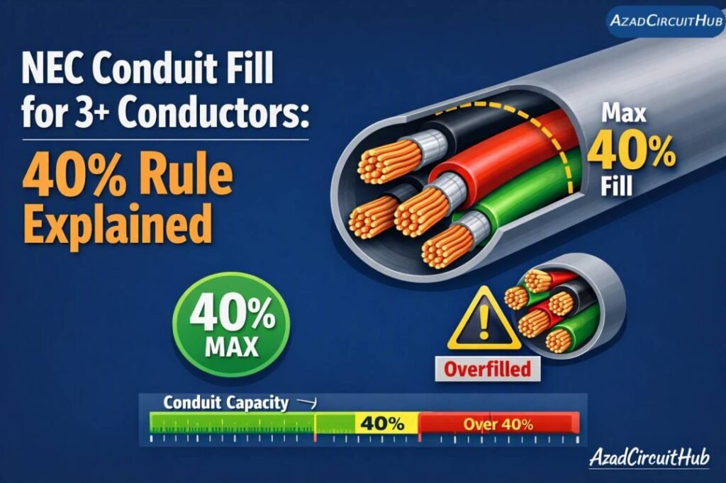
Table of Contents
Table of Contents
What Is the 40% Conduit Fill Rule?
The 40% rule limits the total cross-sectional area occupied by conductors inside a raceway. According to NEC Conduit Fill for 3+ Conductors, the combined conductor area cannot exceed 40% of the raceway’s available internal area.
For example, if a conduit has an internal area of 1.00 square inch, the maximum allowable conductor area for three or more conductors is:
1.00 × 40% = 0.40 square inch
Therefore, all conductors counted for the fill calculation must have a combined area of 0.40 square inch or less.
This is the basic principle behind conduit fill 3 or more conductors 40 percent calculations.
The purpose is not simply to leave empty space. Adequate free space reduces friction during wire pulling and provides room for conductors to move without excessive pressure or damage to insulation.
Conduit Fill Percentage by Number of Conductors
The NEC uses different maximum fill percentages depending on how many conductors are installed in a raceway.
| Number of Conductors | Maximum Fill | Calculation Basis |
|---|---|---|
| 1 | 53% | Internal raceway area × 0.53 |
| 2 | 31% | Internal raceway area × 0.31 |
| NEC Conduit Fill for 3+ Conductors | 40% | Internal raceway area × 0.40 |
The distinction matters because applying the 40% limit to every installation can produce an incorrect result. The number of conductors must first be established.
For three or more conductors, conduit fill 3 or more conductors 40 percent is the standard calculation concept used for raceway sizing.
If you need to check different raceway sizes quickly, use our conduit fill calculator by diameter to compare the available internal area with the conductor area.
How to Calculate Conduit Fill for 3+ Conductors
The calculation can be completed in four basic steps.
Step 1: Identify the Conductors
Record the wire size, insulation type, and number of conductors.
For example, suppose a raceway contains:
- Six 10 AWG copper THHN conductors
- One 10 AWG equipment grounding conductor
The conductor sizes should be verified before calculating the total area.
Step 2: Find the Conductor Area
Conductor dimensions can be obtained from the applicable NEC conductor tables. The area depends on the conductor size and insulation designation.
The physical area of a 10 AWG THHN conductor is not necessarily the same as the area shown for a different insulation type or conductor construction.
Step 3: Add the Areas
Multiply the area of each conductor by the number of conductors.
Total conductor area = conductor area × quantity
Then add the areas when different wire sizes are present.
| Conductor | Quantity | Individual Area | Total Area |
|---|---|---|---|
| 10 AWG THHN | 6 | A | 6A |
| 10 AWG grounding conductor | 1 | A | A |
| Total | 7 | — | 7A |
The actual NEC conductor area should be used instead of estimating from the wire gauge alone.
Step 4: Compare With 40% of Raceway Area
Calculate the permitted conductor area:
Maximum conductor area = internal conduit area × 0.40
The installation complies with the fill limit when the total conductor area is equal to or less than the permitted area.
This is the central calculation for Conduit Fill for 3+ Conductors 40 percent applications.
Example Calculation
Consider a conduit with an internal area of 0.533 square inches.
Because the installation contains three or more conductors, the maximum usable conductor area is:
0.533 × 0.40 = 0.2132 square inches
Therefore, the combined conductor area must not exceed 0.2132 square inches.
| Calculation | Result |
|---|---|
| Raceway internal area | 0.533 in² |
| NEC fill percentage | 40% |
| Maximum conductor area | 0.2132 in² |
| Actual conductor area | Must be ≤ 0.2132 in² |
| Result | Pass if actual area is within limit |
This example demonstrates why conduit size cannot be selected simply by counting conductors. The actual conductor dimensions must be included.
For larger projects, a conduit capacity calculator can simplify the comparison between different conduit sizes and conductor combinations.
How Wire Size Affects Conduit Fill
Larger conductors occupy more physical space. Moving from 12 AWG to 10 AWG, or from 10 AWG to 8 AWG, can significantly increase the total area inside the raceway.
| Wire Size | Relative Space Requirement | Common Uses |
|---|---|---|
| 14 AWG | Low | Lighting and control circuits |
| 12 AWG | Low to moderate | General branch circuits |
| 10 AWG | Moderate | Higher-load branch circuits |
| 8 AWG | Higher | Larger branch circuits and feeders |
| 6 AWG | High | Feeders and larger loads |
| 4 AWG and larger | Very high | Large feeders and equipment |
The conductor insulation also matters because NEC fill tables use the overall dimensions of the conductor, not just the copper or aluminum core.
Does the Ground Wire Count for Conduit Fill?
The equipment grounding conductor is relevant to conduit fill calculations, but the NEC provides specific rules for how grounding and bonding conductors are treated when determining raceway fill.
If multiple grounding conductors are present, their treatment may differ from a simple count of all conductors. Where conductors of different sizes are installed, the largest applicable grounding or bonding conductor can also affect the calculation.
This is one reason it is better to use the applicable NEC tables rather than relying on a simple wire-count shortcut.
For a quick reference to allowable raceway occupancy, check our conduit fill chart before selecting a conduit size.
Conduit Fill Is Different From Ampacity Derating
A common mistake is assuming that passing the conduit fill calculation means the installation is complete.
It does not.
Conduit fill determines how much physical space the conductors occupy. Ampacity adjustment determines whether current-carrying conductors need their allowable ampacity reduced because of heat.
These are separate requirements.
| Requirement | What It Checks |
|---|---|
| Conduit fill | Physical space inside raceway |
| Ampacity | Current-carrying capacity |
| Temperature rating | Maximum conductor operating temperature |
| Voltage drop | Voltage loss along conductor length |
| Raceway protection | Mechanical protection of wiring |
For example, an installation may pass the 40% fill calculation but still require conductor ampacity adjustment because of the number of current-carrying conductors.
Always perform both calculations where applicable.
Maximum Conduit Fill Percentage and Raceway Selection
The maximum permitted fill depends on the number of conductors. For three or more conductors, the 40% limit is the value normally used.
A larger conduit may be required when the conductor area exceeds the permitted percentage.
| Situation | Possible Solution |
|---|---|
| Conductors exceed 40% | Increase conduit size |
| Too many current-carrying conductors | Check ampacity adjustment |
| Long conduit run | Evaluate pulling tension and bends |
| Mixed conductor sizes | Calculate each conductor area |
| Future expansion expected | Consider additional raceway capacity |
Our guide to max conduit fill percentage provides a useful reference when comparing the allowable occupancy of different raceway configurations.
Practical Tips for Avoiding Conduit Fill Problems
A few simple checks can prevent most conduit fill problems during design and installation.
- Confirm the actual conductor insulation type.
- Count the conductors before selecting the conduit.
- Use the conductor dimensions from the applicable NEC tables.
- Calculate total conductor area.
- Determine the allowable raceway area.
- Check the 40% limit for three or more conductors.
- Separately verify ampacity adjustment requirements.
- Consider the number of bends and the length of the raceway.
- Avoid selecting a conduit size that only barely passes when installation conditions are difficult.
- Verify local electrical requirements before installation.
A conduit wire fill chart can also help during field work when you need to compare common wire sizes and raceway options quickly.
Frequently Asked Questions
What is the 40% conduit fill rule?
The 40% rule generally applies when three or more conductors are installed in a raceway. The combined cross-sectional area of the conductors must not exceed 40% of the raceway’s available internal area under the applicable NEC rules.
Does conduit fill include the ground wire?
Grounding conductors are considered under the NEC conduit fill provisions, but their treatment depends on the specific installation. Multiple grounding conductors and different conductor sizes require the applicable NEC calculation rather than simply counting every wire equally.
Is conduit fill always 40%?
No. The permitted fill percentage depends on the number of conductors. One conductor generally uses a 53% limit, two conductors use 31%, and Conduit Fill for 3+ Conductors generally use 40%.
Can I use a conduit fill chart instead of calculating?
A conduit fill chart can be useful for common combinations, but it should match the conductor type, wire size, raceway type, and applicable NEC requirements. For unusual combinations, perform the calculation using the actual conductor dimensions.
Does conduit fill affect wire ampacity?
Conduit fill and ampacity are separate considerations. A raceway can meet the physical fill requirement while the conductors still require ampacity adjustment because of the number of current-carrying conductors. Both requirements should be checked during electrical design.
Final Takeaway
The 40% limit is one of the most important values to remember when working with Conduit Fill for 3+ Conductors. The calculation starts with the actual conductor dimensions, adds the total occupied area, and compares it with 40% of the raceway’s internal area.
For conduit fill 3 or more conductors 40 percent calculations, do not rely only on wire gauge or the number of wires. Conductor insulation, actual dimensions, raceway type, grounding conductors, and other NEC requirements can affect the final selection.
Once the fill calculation is complete, also check ampacity adjustment, voltage drop, temperature limitations, and installation conditions. This approach produces a more reliable conduit selection and reduces problems during wire pulling and inspection.
Get new guides in your feed. Follow Electrical Insights on LinkedIn for new electrical standards guides, calculators and design tips from Azad Circuit Hub.
#NECConduitFill, #ConduitFill, #NECCode, #ElectricalCode, #ElectricalWiring, #ConduitSizing, #Electricians, #ElectricalEngineering, #NEC40PercentRule, #ElectricalInstallation
