
Wire Fill Chart for Conduit: NEC Fill Rules, EMT, PVC and Conduit Sizing
A proper conduit fill calculation ensures that conductors can be installed without excessive crowding, overheating, or damage to the insulation. The Wire Fill Chart for Conduit below provides a practical starting point for electricians, engineers, designers, and DIY electrical projects using common conductor sizes and raceways.
Under NEC Chapter 9, Table 1, the maximum allowable conduit fill depends on the number of conductors. One conductor may occupy up to 53% of the raceway’s internal area, two conductors up to 31%, and more than two conductors up to 40%.
Wire Fill Chart for Conduit
| Conduit Fill Topic | NEC Fill Limit / Quick Reference | Main NEC Reference |
|---|---|---|
| 1 conductor in conduit | 53% of internal area | NEC Chapter 9, Table 1 |
| 2 conductors in conduit | 31% of internal area | NEC Chapter 9, Table 1 |
| 3+ conductors in conduit | 40% of internal area | NEC Chapter 9, Table 1 |
| EMT conduit fill | 40% for 3+ conductors | NEC 358 + Chapter 9 |
| PVC conduit fill | 40% for 3+ conductors | NEC 352 + Chapter 9 |
| Electrical conduit fill | 40% for 3+ conductors | NEC Chapter 9, Table 1 |
| Wire fill chart EMT | Calculate conductor area vs. EMT area | NEC Chapter 9, Tables 4 & 5 |
| EMT fill chart | Raceway area × 40% | NEC Chapter 9, Tables 4 & 5 |
| PVC conduit fill chart | Raceway area × 40% | NEC 352 + Chapter 9 |
| Conduit sizing | Total wire area must stay within permitted fill | NEC Chapter 9 |
| NEC wire fill chart | 53%, 31%, or 40% depending on conductor count | NEC Chapter 9, Table 1 |
| Conduit capacity chart | Based on raceway inside area and conductor size | NEC Chapter 9 |
| Conduit size chart | Select trade size from allowable fill area | NEC Chapter 9, Table 4 |
| Wire conduit chart | Compare conductor area with raceway capacity | NEC Chapter 9, Tables 4 & 5 |
NEC Conduit Fill Percentages
The basic Wire Fill Chart for Conduit rules are straightforward. The number of conductors determines the percentage of the internal raceway area that may be occupied.
| Number of Conductors | Maximum Fill | Calculation |
|---|---|---|
| 1 | 53% | Raceway area × 0.53 |
| 2 | 31% | Raceway area × 0.31 |
| 3 or more | 40% | Raceway area × 0.40 |
| Nipples 24 in. or less | Special rules may apply | Check NEC 358.22, 344.22, 352.22, etc. |
For most feeder, branch-circuit, and control wiring installations containing three or more conductors, the 40% rule is the value most often used.
Need a faster way to check conduit capacity? Use our Conduit Fill Calculator to determine how many wires can safely fit inside EMT, PVC, and other conduit types.
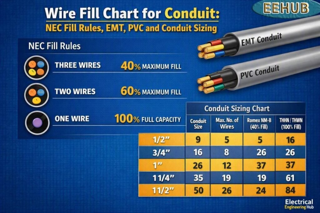
Table of Contents
Table of Contents
EMT Conduit Fill Chart
The following practical Wire Fill Chart for Conduit uses common EMT internal areas from NEC Chapter 9 raceway dimensions. The maximum usable area shown is 40%, which applies when more than two conductors are installed.
| EMT Size | Approx. Internal Area (in²) | 40% Fill Area (in²) |
|---|---|---|
| 1/2 in. | 0.122 | 0.049 |
| 3/4 in. | 0.213 | 0.085 |
| 1 in. | 0.346 | 0.138 |
| 1-1/4 in. | 0.598 | 0.239 |
| 1-1/2 in. | 0.832 | 0.333 |
| 2 in. | 1.363 | 0.545 |
| 2-1/2 in. | 2.258 | 0.903 |
| 3 in. | 3.538 | 1.415 |
| 3-1/2 in. | 4.618 | 1.847 |
| 4 in. | 5.902 | 2.361 |
These figures are useful for preliminary conduit sizing. Always verify the exact raceway type, dimensions, conductor insulation, and applicable NEC table before final installation.
Wire Fill Chart for Common THHN/THWN Conductors
Conductor dimensions matter just as much as conduit diameter. Two wires with the same ampacity can have different outside diameters because of insulation type and construction.
The approximate conductor areas below are commonly used for conduit-fill calculations.
| Conductor Size | Approx. Area (in²) |
|---|---|
| 14 AWG | 0.0097 |
| 12 AWG | 0.0133 |
| 10 AWG | 0.0211 |
| 8 AWG | 0.0366 |
| 6 AWG | 0.0507 |
| 4 AWG | 0.0824 |
| 3 AWG | 0.0973 |
| 2 AWG | 0.1158 |
| 1 AWG | 0.1562 |
| 1/0 AWG | 0.1855 |
| 2/0 AWG | 0.2223 |
| 3/0 AWG | 0.2679 |
| 4/0 AWG | 0.3237 |
| 250 kcmil | 0.3970 |
| 300 kcmil | 0.4608 |
| 350 kcmil | 0.5242 |
| 400 kcmil | 0.5885 |
| 500 kcmil | 0.7073 |
Conductor areas should be checked against the applicable NEC Chapter 9, Table 5 conductor dimensions for the specific insulation and conductor type being installed.
Conduit Capacity Chart for Common Wire Sizes
This conduit capacity chart gives a useful quick reference for common copper THHN/THWN conductors in EMT. Values are based on the 40% fill limit and should be treated as planning values rather than a substitute for a final NEC calculation.
| EMT Size | 12 AWG | 10 AWG | 8 AWG | 6 AWG | 4 AWG | 2 AWG |
|---|---|---|---|---|---|---|
| 1/2 in. | 3 | 2 | 1 | 0 | 0 | 0 |
| 3/4 in. | 6 | 4 | 2 | 1 | 1 | 0 |
| 1 in. | 10 | 6 | 3 | 2 | 1 | 1 |
| 1-1/4 in. | 17 | 11 | 6 | 4 | 2 | 2 |
| 1-1/2 in. | 25 | 15 | 9 | 6 | 4 | 2 |
| 2 in. | 41 | 25 | 14 | 10 | 6 | 4 |
| 2-1/2 in. | 67 | 42 | 24 | 17 | 10 | 7 |
| 3 in. | 106 | 67 | 38 | 27 | 17 | 12 |
| 4 in. | 177 | 111 | 64 | 46 | 28 | 20 |
The table is rounded down to whole conductors and does not account for every installation-specific adjustment.
For a quick NEC-based conduit sizing check, try our Conduit Fill Calculator. It helps you calculate conductor fill and select an appropriate conduit size with less guesswork.
PVC Conduit Fill Chart
PVC raceways are also widely used for underground feeders, outdoor electrical systems, and locations where corrosion resistance is important. A PVC conduit fill chart follows the same basic NEC fill percentages, but the internal area changes with the raceway trade size and schedule.
| PVC Schedule 40 Size | Approx. Internal Area (in²) | 40% Fill Area (in²) |
|---|---|---|
| 1/2 in. | 0.285 | 0.114 |
| 3/4 in. | 0.533 | 0.213 |
| 1 in. | 0.832 | 0.333 |
| 1-1/4 in. | 1.453 | 0.581 |
| 1-1/2 in. | 2.036 | 0.814 |
| 2 in. | 3.356 | 1.342 |
| 2-1/2 in. | 5.858 | 2.343 |
| 3 in. | 8.700 | 3.480 |
| 3-1/2 in. | 11.698 | 4.679 |
| 4 in. | 14.753 | 5.901 |
PVC Schedule 80 has thicker walls and therefore a smaller internal diameter than Schedule 40 of the same trade size. The correct table must therefore be used for the actual raceway. For more detailed charts visit our guide on pvc conduit fill chart here.
How to Calculate Conduit Fill
The basic Wire Fill Chart for Conduit calculation uses the total cross-sectional area of all conductors.
The formula is:
Conduit Fill % = Total Conductor Area ÷ Internal Conduit Area × 100
For example, suppose a 1-inch EMT contains six 12 AWG THHN conductors.
Approximate area of one 12 AWG conductor = 0.0133 in²
Total conductor area:
6 × 0.0133 = 0.0798 in²
A 1-inch EMT has an approximate internal area of 0.346 in².
Fill percentage:
0.0798 ÷ 0.346 × 100 = 23.1%
Because the installation has more than two conductors, the maximum permitted fill is generally 40%. Therefore, the calculated 23.1% is below the normal maximum.
Conduit Fill Table: Quick Selection Guide
| Application | Common Raceway Choice | Main Consideration |
|---|---|---|
| Residential branch circuits | 1/2–1 in. EMT/PVC | Conductor count |
| Small feeders | 1–2 in. EMT/PVC | Wire size and bend space |
| Large feeders | 2–4 in. EMT/PVC | Conductor diameter |
| Underground feeders | PVC Schedule 40/80 | Burial and physical protection |
| Industrial control wiring | EMT | High conductor count |
| Solar DC circuits | EMT/PVC | Conductor insulation and grouping |
| Service conductors | EMT/PVC/RMC | NEC service requirements |
Flexible Conduit Fill Chart
Flexible conduit needs careful sizing because its usable interior space varies by trade size and installation type. A Flexible Conduit Fill Chart helps determine how many conductors can be installed while staying within NEC fill limits.
| Conduit Size | Typical 40% Fill Area | Common Use |
|---|---|---|
| 1/2 in. | Limited | Small control wiring |
| 3/4 in. | Moderate | Branch circuits |
| 1 in. | Larger | Multiple conductors |
| 1-1/4 in. | High | Larger cable groups |
For exact conductor capacity, compare the cable’s actual area with the permitted fill area and account for the number of conductors. See the complete Flexible Conduit Fill Chart for detailed sizing guidance, conductor limits, and practical examples.
Liquidtight Flexible Nonmetallic Conduit Fill Chart
Liquidtight flexible nonmetallic conduit (LFNC) must be sized according to NEC conduit-fill limits, conductor dimensions, and the number of wires installed. The following quick reference helps when selecting LFNC for branch circuits and equipment connections.
| LFNC Trade Size | Typical Maximum Fill | Common Use |
|---|---|---|
| 1/2 in. | 40% | Small branch circuits |
| 3/4 in. | 40% | Multiple conductors |
| 1 in. | 40% | Larger branch circuits |
| 1-1/4 in. | 40% | Feeder applications |
For conductor-specific calculations, see the complete liquidtight flexible nonmetallic conduit fill chart for allowable wire combinations, conductor sizes, and NEC fill requirements.
Romex Conduit Fill Chart
Romex (NM-B) cable can be installed in conduit only where permitted by the NEC, and its overall cable dimensions must be used when calculating conduit fill. A romex conduit fill chart helps estimate how many cables can fit while staying within NEC fill limits.
| NM-B Cable | Typical Conduit Starting Point |
|---|---|
| 14/2 | 1/2 in. |
| 12/2 | 1/2 in. |
| 10/2 | 3/4 in. |
| 12/3 | 3/4 in. |
For exact conductor and cable combinations, see our detailed Romex conduit fill chart with NEC-based calculations, cable dimensions, and conduit sizing guidance.
Conduit Fill Chart for Cat6 Cable
For a quick NEC-style planning reference, Cat6 cable is generally treated as a communications cable, and conduit capacity depends on the cable’s actual outside diameter. The table below uses an example 0.25-inch Cat6 cable diameter.
| Conduit Size | Approx. Cat6 Cables at 40% Fill* | Typical Use |
|---|---|---|
| 1/2 in. | 5 | Small data runs |
| 3/4 in. | 9 | Small office/network runs |
| 1 in. | 15 | Medium cable bundles |
| 1-1/4 in. | 24 | Larger network runs |
| 1-1/2 in. | 33 | High-density cabling |
| 2 in. | 53 | Large cable bundles |
| 2-1/2 in. | 79 | Large commercial installations |
| 3 in. | 120 | High-density pathways |
*Approximate values based on a 0.25-inch cable OD and 40% conduit fill. Actual capacity changes with the Cat6 cable’s manufacturer-specified diameter.
Formula:
Number of Cat6 cables = 40% usable conduit area ÷ Cat6 cable area
For example, a 0.25-inch Cat6 cable has an approximate area of:
π × (0.25 ÷ 2)² = 0.0491 in²
For an accurate installation, use the actual Cat6 outside diameter and applicable NEC requirements, particularly NEC Chapter 8 for communications circuits and Chapter 9 where applicable to raceway fill.\
Fire Alarm Conduit Fill Chart
For fire alarm wiring, conduit fill is determined by the actual outside diameter of the conductors/cables and the applicable code requirements. The following is a quick planning chart based on 0.20-inch OD fire alarm cable and a 40% fill limit.
| Conduit Size | Approx. Fire Alarm Cables* | Typical Application |
|---|---|---|
| 1/2 in. | 8 | Small device circuits |
| 3/4 in. | 14 | Short fire alarm runs |
| 1 in. | 24 | Multiple initiating/notification circuits |
| 1-1/4 in. | 40 | Larger cable bundles |
| 1-1/2 in. | 54 | Commercial fire alarm installations |
| 2 in. | 87 | Large cable groups |
| 2-1/2 in. | 128 | High-density installations |
| 3 in. | 190 | Large fire alarm pathways |
*Approximate values assuming 0.20-inch cable outside diameter. Actual capacity varies significantly by cable diameter.
Conduit Fill Formula:
Number of cables = Allowable conduit area ÷ Area of one cable
For a fire alarm cable with a 0.20-inch OD:
Cable area = π × (0.20 ÷ 2)² = 0.0314 in²
Code note: Fire alarm circuits are generally governed by NEC Article 760, while raceway fill calculations are addressed by NEC Chapter 9 where applicable. Always use the actual cable dimensions and the applicable code requirements rather than relying on a generic cable-count chart.
Factors That Affect Conduit Sizing
Conduit sizing is not determined by conductor ampacity alone. The following factors should be checked before selecting the raceway:
- Conductor insulation type and outside diameter
- Number of current-carrying conductors
- Raceway material and trade size
- Ambient temperature
- Conductor ampacity and adjustment factors
- Raceway length
- Number and severity of bends
- Pulling tension
- Conductor grouping
- Grounding and bonding requirements
- Cable manufacturer’s dimensions
A raceway that technically meets the fill percentage may still be difficult to pull. For long runs or systems with several bends, selecting a slightly larger raceway can make installation easier and reduce the risk of conductor insulation damage.
Wire Fill Chart for Conduit: Important NEC Rules
The 40% rule is only one part of conduit design. NEC Article 300 and the applicable raceway article also contain requirements affecting conductor installation.
For EMT, NEC Article 358 is the primary reference. Rigid metal conduit is covered by Article 344, while PVC conduit is addressed under Article 352. Flexible raceways have their own requirements.
For conductor dimensions and raceway dimensions, NEC Chapter 9 tables are especially important. Table 1 establishes general conduit-fill percentages, Table 4 provides raceway dimensions and available areas, and Table 5 provides conductor dimensions.
Conduit Fill vs. Ampacity
Conduit fill and ampacity are separate calculations.
A conductor may have enough ampacity for a circuit while the selected conduit is too small for the number of conductors. Conversely, a large conduit does not increase the allowable ampacity of an undersized conductor.
A complete electrical design should therefore check:
- Load current
- Conductor ampacity
- Voltage drop
- Conductor adjustment and correction
- Grounding conductor requirements
- Raceway fill
- Raceway support
- Pulling and bending requirements
This approach prevents conduit sizing from being based only on a simple wire-count chart.
Planning a new electrical installation? Our Conduit Fill Calculator makes it easy to check wire capacity, compare conduit sizes, and avoid common fill calculation errors.
Frequently Asked Questions
How much conduit fill is allowed by NEC?
NEC Chapter 9, Table 1 generally permits 53% fill for one conductor, 31% for two conductors, and 40% for more than two conductors. Other specific raceway or installation conditions can affect the calculation.
How many wires can fit in 1/2-inch EMT?
The answer depends on conductor size and insulation. For example, a 1/2-inch EMT has an approximate internal area of 0.122 in², giving about 0.049 in² at 40% fill. The actual number of conductors must be calculated from their individual areas.
What is the difference between EMT fill and PVC conduit fill?
The same basic NEC fill percentages apply, but EMT and PVC have different internal dimensions. Therefore, the available fill area for the same trade size can be significantly different.
Where can I find the NEC wire fill chart?
NEC Chapter 9 contains the primary tables used for conduit-fill calculations. Table 1 covers fill percentages, Table 4 provides raceway dimensions, and Table 5 provides conductor dimensions.
Can I use a cable in conduit instead of individual wires?
Yes, where the cable type is permitted for the installation. However, cable assemblies must be evaluated using their actual overall dimensions and the applicable NEC rules. Do not treat a multi-conductor cable as several individual wires when the code requires the cable assembly to be considered as a single cable for fill purposes.
Final Takeaway
A reliable Wire Fill Chart for Conduit makes raceway selection faster, but the final design should always use the actual conductor and raceway dimensions. For most installations with three or more conductors, the 40% fill limit is the key starting point. EMT, PVC, RMC, and other raceways can have different internal areas even when their trade sizes are identical.
For professional electrical work, verify the latest NEC requirements, manufacturer dimensions, conductor insulation type, and local electrical code before installation. Proper conduit sizing improves pulling performance, protects conductor insulation, and provides a cleaner and safer electrical installation.
Get new guides in your feed. Follow Electrical Insights on LinkedIn for new electrical standards guides, calculators and design tips from Azad Circuit Hub.
WireFillChart, #ConduitFill, #ConduitSizing, #NEC, #EMTConduit, #PVCConduit, #ElectricalWiring, #WireSizing, #ElectricalEngineering, #ConduitFillCalculator

This is really interesting, You’re a very skilled blogger. I’ve joined your feed and look forward to seeking more of your magnificent post. Also, I’ve shared your site in my social networks!
Good post! We will be linking to this particularly great post on our site. Keep up the great writing
Very well presented. Every quote was awesome and thanks for sharing the content. Keep sharing and keep motivating others.
Pretty! This has been a really wonderful post. Many thanks for providing these details.