
NEC Chapter 9 Table 1: Conduit Fill Percentages Explained
NEC Chapter 9 Table 1 is one of the most important references for determining how much conductor area can be placed inside a raceway. It establishes the maximum allowable conduit fill based on the number of conductors installed. These limits help prevent overcrowding, make wire installation easier, and leave enough room for conductors to dissipate heat.
For most standard conduit sizing calculations, the key percentages are 53%, 31%, and 40%. The applicable percentage depends on whether the raceway contains one conductor, two conductors, or more than two conductors.
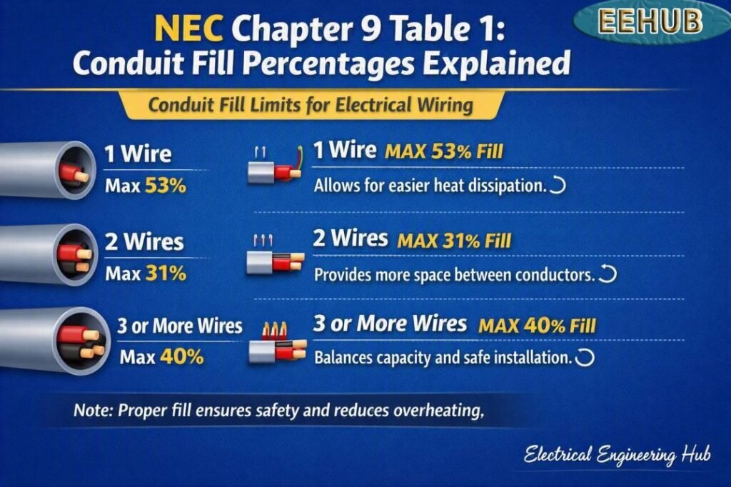
Table of Contents
Table of Contents
Quick NEC Conduit Fill Percentages
| Number of Conductors | Maximum Fill | Typical Application |
|---|---|---|
| 1 conductor | 53% | Single large conductor |
| 2 conductors | 31% | Two conductors in a raceway |
| More than 2 conductors | 40% | Most multi-conductor installations |
| More than 2 conductors with same overall area | 40% | General raceway applications |
These percentages are based on the internal area of the raceway, not simply its nominal trade size. The conductor dimensions and the raceway’s usable internal area must therefore be considered when checking conduit capacity.
For a quick sizing check, a Conduit Fill Calculator can help compare conductor dimensions with the permitted raceway area before selecting a conduit size.
What Is NEC Chapter 9 Table 1?
NEC Chapter 9 Table 1 provides the general percentage limits for conductor fill in raceways. It works together with the other tables in NEC Chapter 9, including tables that provide conductor dimensions, raceway dimensions, and allowable areas.
The basic rule is straightforward:
- One conductor can occupy up to 53% of the raceway’s internal area.
- Two conductors can occupy up to 31%.
- More than two conductors can occupy up to 40%.
The reason the percentage changes is that multiple conductors need sufficient free space for installation and practical wire pulling. A raceway that is technically large enough by area may still be difficult to work with if it is packed too tightly.
Understanding the 53%, 31%, and 40% Rules
The three principal values in NEC Chapter 9 Table 1 are easy to remember, but applying them correctly requires identifying the number of conductors.
53% Fill for One Conductor
A single conductor may occupy up to 53% of the raceway’s internal cross-sectional area. This higher allowance applies because there is only one conductor and therefore more open space around it.
For example, if a raceway has an internal area of 1.00 square inch, the maximum conductor area under the 53% rule would be:
1.00 × 0.53 = 0.53 square inch
This does not mean the conductor’s insulation can be ignored. The outside diameter and corresponding conductor area must be used for conduit fill calculations.
31% Fill for Two Conductors
When two conductors are installed, the maximum allowable fill is 31%.
For a raceway with 1.00 square inch of internal area:
1.00 × 0.31 = 0.31 square inch
The combined cross-sectional area of both conductors must not exceed this value.
This lower percentage provides more free space around the conductors than the single-conductor rule.
40% Fill for More Than Two Conductors
For more than two conductors, the general maximum fill is 40%.
For example, a raceway with 1.50 square inches of internal area has a maximum conductor area of:
1.50 × 0.40 = 0.60 square inch
The total area of all conductors must remain at or below the permitted value.
This 40% rule is especially important in common electrical installations containing phase conductors, neutral conductors, grounding conductors, and control wiring.
How to Calculate Conduit Fill
A basic conduit fill calculation follows three steps.
- Determine the internal area of the selected raceway.
- Determine the total outside area of the conductors.
- Apply the appropriate fill percentage.
The basic equation is:
Maximum allowable conductor area = Raceway internal area × Fill percentage
For example, suppose a conduit has an internal area of 0.75 square inch and contains four conductors.
Because there are more than two conductors, the 40% limit applies:
0.75 × 0.40 = 0.30 square inch
Therefore, the combined conductor area should not exceed 0.30 square inch.
For a detailed calculation involving different wire sizes, conduit types, and conductor dimensions, a Conduit Fill Calculator can reduce manual calculations and make comparison between raceway sizes easier.
Conductor Area Matters More Than Wire Gauge Alone
A common mistake is to calculate conduit fill using only the AWG size printed on the conductor. The actual outside dimensions can vary depending on conductor insulation type and construction.
For example, two conductors with the same copper size may have different overall diameters because one has thicker insulation or a different jacket.
For accurate raceway sizing, check:
- Conductor insulation type
- Conductor size
- Overall outside diameter
- Number of conductors
- Raceway internal diameter
- Raceway type
NEC Chapter 9 tables provide the dimensional information needed for many of these calculations.
Example: Four Conductors in EMT
Consider four conductors installed in an EMT raceway. Assume the combined outside cross-sectional area of the conductors is 0.28 square inch.
Because there are more than two conductors, the maximum fill is 40%.
The minimum required internal raceway area would be:
0.28 ÷ 0.40 = 0.70 square inch
The selected EMT must therefore provide at least 0.70 square inch of usable internal area, subject to the applicable NEC requirements and the actual conductor dimensions.
This calculation demonstrates why selecting conduit based only on nominal trade size can lead to errors.
NEC Chapter 9 Table 1 and Raceway Sizing
NEC Chapter 9 Table 1 does not tell you the exact conduit size by itself. Instead, it establishes the percentage limit that must be applied to the raceway’s internal area.
Other Chapter 9 tables provide important supporting information. For example, raceway dimension tables can be used to determine the internal area of different raceway types, while conductor tables provide dimensions for various wire sizes and insulation types.
The final conduit size is selected by comparing the total conductor area against the permitted fill area.
Practical Conduit Fill Reference
| Conductors in Raceway | Fill Limit | Calculation |
|---|---|---|
| 1 | 53% | Raceway area × 0.53 |
| 2 | 31% | Raceway area × 0.31 |
| 3 or more | 40% | Raceway area × 0.40 |
These values are the core of NEC Chapter 9 Table 1 and are widely used in conduit sizing work.
Why Conduit Fill Limits Matter
Conduit fill is not simply a paperwork requirement. Excessive conductor crowding can make wire pulling difficult and increase the chance of damaging insulation during installation.
Proper fill also provides practical working space for conductors and helps electricians install or replace wiring more safely.
Other factors still need to be checked. Conduit fill does not replace ampacity calculations, conductor adjustment requirements, voltage-drop calculations, grounding requirements, or raceway installation rules.
For projects involving several wire sizes, parallel conductors, or multiple raceway systems, using a Conduit Fill Calculator alongside the applicable NEC tables can provide a faster preliminary sizing check.
Common Mistakes When Applying the Fill Rules
Several errors appear frequently during conduit sizing.
Using 40% for Every Installation
The 40% rule is common, but it is not the universal fill percentage. One and two conductors have different limits.
Ignoring Insulation Dimensions
The copper or aluminum conductor size alone does not establish its occupied area. Overall conductor dimensions matter.
Using Nominal Conduit Area
Trade size is not the same as usable internal area. The actual raceway dimensions should be checked.
Forgetting Other NEC Requirements
A conduit can pass the fill calculation and still require a larger raceway because of other installation considerations.
Frequently Asked Questions
What are the three main conduit fill percentages?
The primary percentages are 53% for one conductor, 31% for two conductors, and 40% for more than two conductors.
Does the 40% rule apply to three conductors?
Yes. Three or more conductors generally fall under the 40% maximum fill requirement in NEC Chapter 9 Table 1.
Is conduit fill based on wire gauge?
Not directly. The calculation uses the conductor’s actual outside dimensions or cross-sectional area, along with the internal area of the raceway.
Can conduit be filled to 100%?
No. Standard raceway fill limits do not permit conductors to occupy the entire internal area. The applicable percentage depends on the number of conductors.
Does conduit fill determine wire ampacity?
No. Conduit fill and conductor ampacity are separate calculations. Ampacity, adjustment factors, temperature limitations, and other NEC requirements must be evaluated separately.
Final Takeaway
NEC Chapter 9 Table 1 provides a simple foundation for raceway fill calculations: 53% for one conductor, 31% for two conductors, and 40% for more than two conductors. The challenge is applying those percentages with the correct conductor dimensions and actual raceway internal area.
For practical electrical design, always combine the fill calculation with the relevant NEC raceway, conductor, ampacity, grounding, and installation requirements. When several conductors or conduit sizes are involved, a Conduit Fill Calculator can make the initial sizing process faster and help identify a suitable raceway before final code verification.
Get new guides in your feed. Follow Electrical Insights on LinkedIn for new electrical standards guides, calculators and design tips from Azad Circuit Hub.
NECChapter9, #ConduitFill, #NECStandards, #ConduitSizing, #ElectricalCode, #NECTable1, #ElectricalEngineering, #WireFill, #ConduitDesign, #Electricians
