How to Calculate Conduit Fill: Step-by-Step Guide
Knowing how to calculate conduit fill is important when installing electrical wiring in PVC, EMT, IMC, RMC, or other raceway systems. Proper conduit fill leaves enough space for conductors, makes pulling wires easier, and helps ensure the installation meets the applicable electrical code.
Conduit fill is based on the total cross-sectional area of the conductors compared with the usable internal area of the raceway. The permitted percentage depends mainly on the number of conductors installed.
Conduit Fill Quick Reference
| Number of Conductors | Maximum Fill | Typical Use |
|---|---|---|
| 1 | 53% | Single conductor |
| 2 | 31% | Two conductors |
| 3 or more | 40% | Three or more conductors |
| 4 or more | 40% | Common multi-conductor installation |
These percentages are commonly associated with NEC Chapter 9, Table 1. Local requirements and the applicable edition of the electrical code should always be checked before installation.
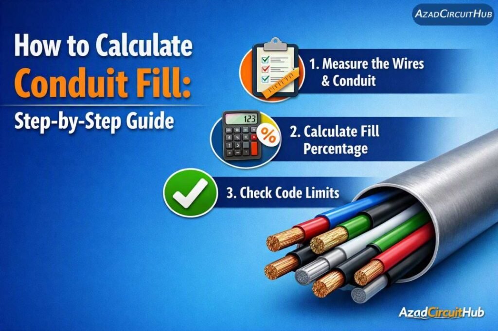
Table of Contents
Table of Contents
How to Calculate Conduit Fill
The basic calculation requires three pieces of information: the number of conductors, the conductor dimensions or area, and the internal area of the conduit.
The general formula is:
Conduit Fill % = Total conductor area ÷ Internal conduit area × 100
For three or more conductors, the total conductor area must normally remain at or below 40% of the raceway’s available internal area under NEC conduit-fill rules.
For example, suppose a conduit contains four conductors, each with an approximate cross-sectional area of 10 mm². The total conductor area is:
4 × 10 = 40 mm²
If the conduit has an internal area of 150 mm²:
Fill = 40 ÷ 150 × 100 = 26.7%
Since 26.7% is below the 40% limit used for three or more conductors, the calculated fill is within that limit.
For faster sizing work, you can use an electrical conduit size calculator to compare conductor quantity, conductor size, and raceway dimensions without repeating the calculation manually.
Step 1: Count the Conductors
Start by counting every conductor that will occupy the raceway. Include power conductors, neutral conductors, grounding conductors, and other wires when the applicable code requires them to be included in the fill calculation.
The number of conductors affects the permitted fill percentage.
| Conductors in Raceway | Maximum Percentage |
|---|---|
| 1 | 53% |
| 2 | 31% |
| 3 or more | 40% |
Do not assume that the number of circuits alone determines the fill. The actual conductors installed inside the raceway must be considered.
Step 2: Determine Conductor Area
Next, find the conductor area from the manufacturer’s data or the applicable wire specification.
For conductors listed by AWG size, NEC Chapter 9 tables can provide conductor dimensions and approximate areas. For metric cables, use the manufacturer’s stated dimensions and construction details.
| Wire Size | Approx. Conductor Area |
|---|---|
| 14 AWG | 2.08 mm² |
| 12 AWG | 3.31 mm² |
| 10 AWG | 5.26 mm² |
| 8 AWG | 8.37 mm² |
| 6 AWG | 13.3 mm² |
| 4 AWG | 21.2 mm² |
| 2 AWG | 33.6 mm² |
For stranded conductors, the overall cable diameter can be more useful than simply using the nominal copper area, particularly when insulation thickness affects the occupied space.
Step 3: Calculate Total Conductor Area
Multiply the area of each conductor by the number of conductors of that size.
For example:
| Conductor | Quantity | Area Each | Total Area |
|---|---|---|---|
| 12 AWG | 4 | 3.31 mm² | 13.24 mm² |
| 10 AWG | 2 | 5.26 mm² | 10.52 mm² |
| Ground | 1 | Manufacturer data | Included as applicable |
Add the relevant conductor areas together to obtain the total occupied area.
This is particularly important when a raceway contains mixed conductor sizes. You cannot simply multiply the largest conductor size by the total number of wires.
Step 4: Find the Conduit Internal Area
The next step is finding the usable internal area of the conduit.
For a circular conduit, the basic geometric formula is:
A = πD² ÷ 4
Where:
- A = internal cross-sectional area
- D = internal diameter
- π = approximately 3.1416
However, the actual internal diameter should come from the conduit manufacturer’s specifications or the applicable code tables where available.
For example, if a raceway has an internal diameter of 20 mm:
A = 3.1416 × 20² ÷ 4
A ≈ 314.16 mm²
For a three-or-more-conductor installation using a 40% fill limit:
314.16 × 0.40 = 125.66 mm²
Therefore, approximately 125.66 mm² is the maximum conductor area allowed under that assumed calculation.
Step 5: Compare the Areas
Once the total conductor area and permitted conduit area are known, compare the two values.
| Calculation | Result |
|---|---|
| Internal conduit area | 314.16 mm² |
| Maximum fill percentage | 40% |
| Usable fill area | 125.66 mm² |
| Total conductor area | 23.76 mm² |
| Calculated fill | 7.56% |
The installation is below the assumed 40% fill limit.
If you work with Australian electrical installations, a dedicated conduit size calculator australia can also help when checking metric cable sizes and local installation requirements. Always verify the final result against the applicable Australian Standard and installation method.
Step 6: Check the Actual Installation Conditions
A conduit-fill calculation is only one part of raceway design. You should also check conductor ampacity, derating, voltage drop, temperature, bending space, and the maximum number of wires permitted by the relevant standard.
Pay attention to:
- Conductor insulation type
- Ambient temperature
- Number of current-carrying conductors
- Conduit material
- Raceway length
- Cable pulling distance
- Bends and offsets
- Junction and pull-box dimensions
- Equipment terminal space
A raceway can satisfy its fill limit while the conductor ampacity still requires a larger wire or different installation arrangement.
Common Conduit Fill Mistakes
One common error is calculating fill from the copper area alone when the applicable table requires the overall conductor dimensions. Another mistake is using the 40% limit for every installation without checking the number of conductors.
Mixed conductor sizes also need separate calculations. For example, six small control wires and two large power cables should not be treated as eight identical conductors.
If you regularly size raceways for panels, motors, controls, or industrial installations, a conduit size calculator can speed up the comparison between available conduit sizes.
Frequently Asked Questions
What is the 40% conduit fill rule?
For many installations with three or more conductors, NEC conduit-fill rules permit conductors to occupy up to 40% of the raceway’s internal area. Other conductor counts have different limits.
How do you calculate conduit fill percentage?
Add the applicable cross-sectional areas of all conductors, divide the result by the conduit’s internal cross-sectional area, and multiply by 100.
Can different wire sizes be installed in the same conduit?
Yes, provided the installation complies with applicable conduit-fill, ampacity, derating, voltage-drop, and other code requirements. Each conductor size should be included using its applicable dimensions.
Does the ground wire count for conduit fill?
The grounding conductor can affect conduit fill, but the treatment depends on the applicable code provisions and conductor arrangement. Check the relevant electrical standard rather than assuming it can always be ignored.
What conduit fill percentage is allowed?
The permitted percentage depends on the number of conductors. Under common NEC rules, the limits are 53% for one conductor, 31% for two conductors, and 40% for three or more conductors. Always verify the applicable code and edition for the installation.
Final Conduit Fill Check
Learning how to calculate conduit fill gives electricians and engineers a practical way to check whether a raceway can accommodate the planned conductors. The process is straightforward: identify the conductors, determine their applicable areas, calculate the conduit’s internal area, apply the permitted fill percentage, and compare the results.
Remember that conduit fill is not the same as complete cable sizing. Ampacity, voltage drop, conductor derating, bending space, and local electrical requirements must also be reviewed before final installation.
Get new guides in your feed. Follow Electrical Insights on LinkedIn for new electrical standards guides, calculators and design tips from Azad Circuit Hub.
#ConduitFill, #HowToCalculateConduitFill, #NECConduitFill, #ConduitSizing, #ElectricalWiring, #NECCode, #ElectricalEngineering, #ConduitFillCalculation, #WireSizing, #ElectricianGuide