Busbar Sizing Chart in Inches: Best Overview
A proper busbar design starts with current, material, temperature rise, fault duty, and installation conditions. Physical dimensions matter because a wider or thicker bar can carry more current.
This Busbar Sizing Chart in Inches provides a practical imperial reference for common copper and aluminum busbar dimensions. It is useful for panelboards, switchboards, distribution panels, MCCs, and industrial control assemblies. Final sizing should still be verified against the equipment standard, manufacturer data, temperature-rise requirements, and available short-circuit current.
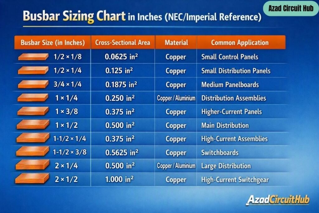
Table of Contents
Table of Contents
Busbar Sizing Chart in Inches
The following table gives commonly used starting dimensions. Actual ampacity can vary significantly with enclosure design, ventilation, orientation, spacing, insulation, and allowable temperature rise.
| Busbar Size in Inches | Cross-Sectional Area | Typical Material | Common Application |
|---|---|---|---|
| 1/2 × 1/8 in | 0.0625 in² | Copper | Small control panels |
| 1/2 × 1/4 in | 0.125 in² | Copper | Small distribution panels |
| 3/4 × 1/4 in | 0.1875 in² | Copper | Medium panelboards |
| 1 × 1/4 in | 0.250 in² | Copper/Aluminum | Distribution assemblies |
| 1 × 3/8 in | 0.375 in² | Copper | Higher-current panels |
| 1 × 1/2 in | 0.500 in² | Copper | Main distribution |
| 1-1/2 × 1/4 in | 0.375 in² | Copper | High-current assemblies |
| 1-1/2 × 3/8 in | 0.5625 in² | Copper | Switchboards |
| 2 × 1/4 in | 0.500 in² | Copper/Aluminum | Large distribution |
| 2 × 1/2 in | 1.000 in² | Copper | High-current switchgear |
The table is a dimensional reference, not an NEC ampacity table. Two busbars with the same cross-sectional area can have different thermal performance because surface area, mounting arrangement, spacing, and cooling conditions are different.
For a complete design, a bus bar size calculator can help establish the required cross-sectional area before selecting the nearest practical imperial dimension.
How Busbar Dimensions Affect Ampacity
Busbar ampacity is closely related to its cross-sectional area and ability to dissipate heat. Increasing the width or thickness increases the available conductor area, but the increase does not translate into a simple universal ampacity value.
For example, a 1 × 1/4 inch bar has a cross-sectional area of 0.25 in²:
Area = Width × Thickness
Area = 1 × 0.25 = 0.25 in²
A 1 × 1/2 inch busbar has twice the cross-sectional area, at 0.50 in². However, the final allowable current cannot simply be assumed to double.
| Design Factor | Effect on Busbar |
|---|---|
| Cross-sectional area | Influences current-carrying capacity |
| Busbar width | Affects surface area and heat dissipation |
| Bar thickness | Increases cross-sectional area and mechanical strength |
| Copper vs aluminum | Changes resistance, weight, and thermal performance |
| Ambient temperature | Higher temperature reduces thermal margin |
| Enclosure size | Affects heat dissipation |
| Bar spacing | Influences cooling and dielectric clearance |
| Joint resistance | Can create local hot spots |
| Short-circuit current | Determines mechanical and thermal fault stress |
This is why a Busbar Sizing Chart in Inches should be used as a design reference rather than as a substitute for equipment testing or manufacturer ratings.
Copper and Aluminum Busbar Sizing
Copper and aluminum are the two most common busbar materials. Copper generally has lower electrical resistance and higher conductivity, while aluminum offers lower weight and can be economical for large installations.
| Property | Copper Busbar | Aluminum Busbar |
|---|---|---|
| Electrical conductivity | Higher | Lower |
| Weight | Higher | Lower |
| Typical connection care | Moderate | Higher |
| Thermal expansion | Lower | Higher |
| Cost | Usually higher | Usually lower |
| Common use | Panels, switchgear, MCCs | Large distribution systems |
When changing from copper to aluminum, the same physical dimensions should not automatically be assumed to provide the same current rating.
NEC Requirements for Busbar Design
The NEC provides installation and equipment requirements, but it does not function as a universal busbar dimension chart.
For example, NEC Article 408 covers switchboards, switchgear, and panelboards. Section 408.3 addresses equipment arrangement and construction requirements, while 408.20 addresses switchboard or switchgear overcurrent protection considerations. NEC requirements must be considered together with the listing and product standard applicable to the assembly.
UL standards are also important. UL 67 applies to panelboards, while UL 891 covers switchboards. These product standards address construction, temperature rise, dielectric performance, short-circuit performance, and other assembly requirements.
This distinction is important when using an imperial busbar dimension table. A bar that appears large enough based only on its cross-sectional area may still fail a temperature-rise or short-circuit requirement.
Busbar Size Calculation Example
Suppose a copper busbar is being considered for a 400 A distribution assembly. The designer first determines the required ampacity based on the assembly’s operating conditions.
The next steps normally include:
- Establish the continuous and noncontinuous load.
- Determine the required current rating.
- Select copper or aluminum.
- Calculate or verify the required cross-sectional area.
- Select a practical width and thickness.
- Check temperature rise.
- Check short-circuit withstand capability.
- Verify clearances and creepage distances.
- Check joints, supports, and connection hardware.
- Confirm the final assembly rating.
For detailed design work, busbar size calculation should account for the installation conditions rather than relying only on a generic ampacity-per-square-inch assumption.
Busbar Thickness and Width Selection
Width is often increased when the designer needs greater surface area or a particular connection arrangement. Thickness can provide additional cross-sectional area and mechanical strength.
For example:
| Dimension | Area |
|---|---|
| 1/2 × 1/4 in | 0.125 in² |
| 3/4 × 1/4 in | 0.1875 in² |
| 1 × 1/4 in | 0.250 in² |
| 1 × 3/8 in | 0.375 in² |
| 1 × 1/2 in | 0.500 in² |
| 1-1/2 × 1/2 in | 0.750 in² |
| 2 × 1/2 in | 1.000 in² |
The required dimension also depends on how the busbar is supported. A large bar carrying high fault current can experience significant electrodynamic forces during a short circuit. Proper supports and spacing are therefore part of busbar design.
If you are comparing metric and imperial dimensions, how to calculate busbar size can also help convert the required cross-sectional area into a practical bar dimension.
Busbar Spacing and Clearance
Current capacity is only one part of a safe busbar arrangement. The designer must also maintain suitable electrical clearance and insulation coordination.
Spacing becomes especially important in low-voltage switchboards and panel assemblies where several phase bars are installed close together.
| Item to Check | Why It Matters |
|---|---|
| Phase-to-phase clearance | Reduces flashover risk |
| Phase-to-ground clearance | Provides insulation distance |
| Bar support spacing | Controls mechanical movement |
| Joint overlap | Reduces connection resistance |
| Hardware torque | Prevents loose connections |
| Insulation barriers | Improves protection against contact |
| Enclosure ventilation | Helps control temperature |
Actual minimum distances should be taken from the applicable equipment standard, listing requirements, insulation system, and manufacturer instructions rather than applying one universal spacing value.
Frequently Asked Questions
What size busbar do I need for 100 amps?
There is no universal busbar dimension for 100 A. Copper or aluminum material, enclosure temperature, mounting arrangement, allowable temperature rise, and assembly construction all affect the required size.
Does the NEC provide a busbar sizing chart?
The NEC provides requirements for electrical equipment and installations, but it does not provide a universal chart assigning a specific copper or aluminum busbar dimension to every current rating. Product standards and manufacturer data are also important.
Is a thicker busbar better than a wider busbar?
Neither is automatically better. Both increase cross-sectional area, but width can improve surface area and connection arrangements, while thickness can improve mechanical strength. The complete thermal and mechanical design determines the suitable dimension.
Can aluminum and copper busbars use the same dimensions?
They should not automatically be treated as equivalent. Copper and aluminum have different electrical and thermal properties, so the required dimensions and connection methods may differ.
How do I calculate busbar cross-sectional area?
For a rectangular bar, multiply width by thickness using the same units. For example, a 1 × 1/2 inch bar has an area of 0.50 in². This calculation establishes area, but it does not by itself establish the final allowable ampacity.
Final Considerations
A Busbar Sizing Chart in Inches is useful when selecting practical bar dimensions for electrical panels and distribution equipment, but dimensional selection should always follow the complete design process. Current rating, conductor material, temperature rise, fault current, enclosure conditions, spacing, supports, and applicable standards all influence the final choice.
For new panel or switchboard designs, use the dimensional chart as a starting point and then verify the selected busbar against the manufacturer’s tested assembly and applicable NEC and UL requirements.
Get new guides in your feed. Follow Electrical Insights on LinkedIn for new electrical standards guides, calculators and design tips from Azad Circuit Hub.
#BusbarSizing, #BusbarSizingChart, #ElectricalEngineering, #NECStandards, #CopperBusbar, #AluminumBusbar, #ElectricalPanel, #BusbarAmpacity, #Switchgear, #PowerDistribution