
CT Sizing for Busbar Protection Schemes: Complete Calculation Guide
Current transformers (CTs) are a critical part of a busbar protection system. Their accuracy, saturation performance, burden, and ratio directly affect how quickly and reliably the protection relay can detect a busbar fault. Incorrect CT selection can cause relay maloperation, delayed tripping, or even failure to clear a severe fault.
CT Sizing for Busbar Protection requires more than selecting a CT ratio based on the normal load current. The protection engineer must consider fault current, CT saturation, secondary burden, knee-point voltage, relay characteristics, and the type of busbar differential scheme being used.
This guide explains the main CT sizing requirements, calculation methods, selection criteria, and practical checks used for busbar protection applications.
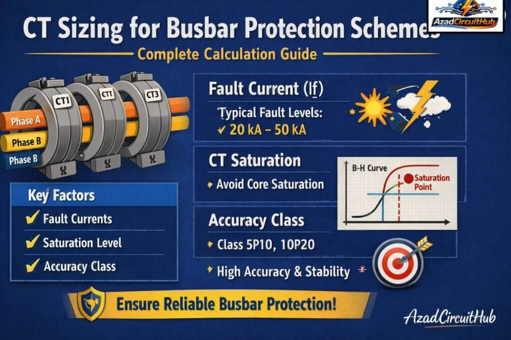
Table of Contents
Table of Contents
Quick CT Sizing Reference
| Parameter | Typical consideration |
|---|---|
| CT primary rating | Above maximum continuous current |
| CT secondary | Commonly 1 A or 5 A |
| Protection class | PX, PS, or suitable differential class |
| CT knee-point voltage | Must exceed calculated protection requirement |
| CT secondary resistance | Used in saturation and stability calculations |
| Relay burden | Included in total secondary circuit burden |
| Lead resistance | Must be included in CT circuit calculations |
| Fault current | Used to assess CT saturation performance |
| CT ratio matching | Important for differential protection |
| Application | Busbar differential, high impedance, low impedance, etc. |
Why CT Sizing Matters in Busbar Protection
Busbar differential protection compares the current entering a busbar with the current leaving it. Under normal operating conditions and external faults, the currents should balance after accounting for CT ratios and relay compensation.
For an internal busbar fault, however, the differential current becomes significant. The protection relay detects this difference and sends a trip command to the associated circuit breakers.
The CTs must reproduce primary current accurately during this process. If one or more CTs saturate heavily during an external fault, a false differential current can appear. This can result in unwanted busbar tripping.
Therefore, CT Sizing for Busbar Protection must focus on both sensitivity for internal faults and stability during heavy external faults.
A properly designed CT circuit should maintain protection security even when the through-fault current is close to the maximum available short-circuit current.
Basic CT Ratio Selection
The first step is to determine the maximum continuous current of the busbar or connected circuit.
For a three-phase system:
Where:
- = full-load current in amperes
- = apparent power in VA
- = line-to-line voltage in volts
For example, consider a 33 kV feeder rated at 20 MVA:
A suitable standard CT ratio could therefore be 400/1 A or 400/5 A, depending on the protection and metering requirements.
However, CT ratio selection should not be based only on normal load current. The protection system must also meet the required fault and saturation conditions.
CT Ratio Selection Example
| System parameter | Example value |
|---|---|
| System voltage | 33 kV |
| Transformer/feed capacity | 20 MVA |
| Calculated current | 350 A |
| Possible CT ratio | 400/1 A |
| Secondary current at rated load | 0.875 A |
| Application | Protection |
For busbar differential protection, CT ratios across different feeders may need to be matched or compensated by the relay, depending on the protection design.
If you are working on the complete busbar protection calculation, use the Busbar Protection Calculator to simplify the key protection calculations and checks.
CT Accuracy and Protection Class
CT accuracy is particularly important in differential protection.
For conventional protection applications, CTs may be specified using classes such as 5P or 10P. For high-impedance differential protection, PX or PS class CTs are commonly specified because the knee-point voltage and excitation characteristics are more important than the standard composite error specification.
Typical CT specifications may include:
| CT characteristic | Purpose |
|---|---|
| Ratio | Converts primary current to secondary current |
| Class | Defines protection accuracy |
| ALF | Indicates accuracy limit performance |
| Knee-point voltage | Indicates onset of magnetic saturation |
| Excitation current | Helps assess CT performance |
| Secondary resistance | Important for stability calculations |
| Rated burden | Defines allowable connected burden |
A protection CT should have sufficient performance at the maximum through-fault current. This is one of the most important principles in CT Sizing for Busbar Protection.
Knee-Point Voltage Requirement
Knee-point voltage is a major consideration for high-impedance busbar differential protection.
The knee point is generally defined as the voltage at which a small increase in voltage produces a large increase in excitation current. Beyond this region, the CT core begins to saturate significantly.
A simplified stability requirement can be expressed as:
Where:
- = CT knee-point voltage
- = maximum secondary through-fault current
- = CT secondary winding resistance
- = resistance of the connected secondary leads
In a practical design, relay resistance, stabilizing resistor effects, and other circuit characteristics may also need to be considered.
Example Knee-Point Calculation
Assume:
- Maximum secondary fault current = 40 A
- CT resistance = 2 Ω
- Lead resistance = 1 Ω
Then:
The selected CT should therefore have a knee-point voltage comfortably above this calculated value, subject to the actual protection scheme and manufacturer’s recommendations.
CT Saturation and Busbar Differential Protection
CT saturation is one of the biggest concerns during external faults.
Consider a fault outside the protected busbar zone. A very high current may flow through one or more feeders. Ideally, the CTs reproduce the current accurately so that the relay sees balanced currents.
If one CT saturates before another, the secondary currents become unequal. The differential relay may then detect a false operating current.
The CT design must therefore provide sufficient excitation capability and knee-point voltage to maintain stability during the worst credible external fault.
Important saturation factors include:
- Maximum through-fault current
- CT secondary resistance
- Lead resistance
- Relay burden
- CT core characteristics
- DC offset in the fault current
- X/R ratio of the system
- Residual flux in the CT core
This is why CT Sizing for Busbar Protection should always include a stability assessment rather than relying only on the CT ratio.
High-Impedance vs Low-Impedance Busbar Protection
The required CT characteristics depend strongly on the differential protection scheme.
| Feature | High-impedance scheme | Low-impedance scheme |
|---|---|---|
| CT requirements | Highly matched characteristics | Relay compensates CT differences |
| CT class | Often PX/PS | Often suitable 5P/TP class depending on relay |
| Stability | Strongly dependent on CT knee point | Managed by relay algorithm |
| Wiring | Conventional CT summation circuits | Individual CT inputs |
| Flexibility | Lower | Higher |
| CT saturation tolerance | Requires careful design | Generally better managed |
| Application | Traditional busbar schemes | Modern numerical relays |
Modern numerical busbar relays can provide sophisticated bias and saturation detection functions. Even so, CT selection remains essential for dependable protection.
CT Burden Calculation
CT burden is the total impedance connected to the CT secondary circuit.
A simplified calculation is:
The associated voltage requirement is:
Where is the secondary current.
Typical Burden Components
| Component | Example |
|---|---|
| Relay input burden | 0.2 Ω |
| CT secondary resistance | 2.0 Ω |
| Lead resistance | 1.0 Ω |
| Total circuit resistance | 3.2 Ω |
| Secondary fault current | 40 A |
| Approximate voltage | 128 V |
The actual manufacturer’s data should always be used for the relay input burden and CT characteristics.
Reducing secondary lead length and resistance can improve CT performance, particularly in high-impedance differential applications.
Practical CT Selection Checklist
Before finalizing a busbar CT, check the following:
- Calculate the maximum continuous current.
- Select an appropriate CT ratio.
- Determine the maximum through-fault current.
- Calculate the maximum secondary fault current.
- Determine CT secondary winding resistance.
- Calculate the complete secondary circuit burden.
- Check the required knee-point voltage.
- Verify the CT protection class.
- Check CT ratio matching between circuits.
- Confirm the relay manufacturer’s requirements.
- Assess CT saturation under external faults.
- Verify the stability and sensitivity of the complete scheme.
A detailed Busbar Protection Calculator can also help engineers organize these calculations before final CT selection.
Example CT Sizing Calculation
Suppose a 132 kV busbar uses CTs with a 1200/1 A ratio. The maximum external fault current is 31 kA.
The secondary fault current is:
If the CT resistance is 3 Ω and the lead resistance is 1.5 Ω:
A practical CT specification would normally provide an adequate margin above this calculated value rather than selecting a CT exactly at the minimum requirement.
This example shows why the short-circuit level can have a major effect on CT selection even when the normal busbar current is relatively stable.
Common CT Sizing Mistakes
Several mistakes can reduce busbar protection reliability.
Selecting CTs Only From Load Current
A CT that works well for normal load may saturate during a high external fault. Fault current must always be considered.
Ignoring Lead Resistance
Long secondary cables can add significant resistance. This increases the required CT voltage and can worsen saturation.
Using Inappropriate CT Classes
Metering CTs are not automatically suitable for protection. Differential protection needs CTs with characteristics appropriate for the selected scheme.
Neglecting CT Ratio Differences
Different feeder ratings can result in different CT ratios. The relay must be capable of handling these ratios or suitable matching arrangements must be provided.
Selecting the Minimum Knee-Point Voltage
A calculated minimum should not normally be treated as the final specification. Engineering margin and manufacturer recommendations should be considered.
Final CT Sizing Checklist
| Check | Required |
|---|---|
| Maximum load current | Yes |
| CT ratio | Yes |
| Maximum fault current | Yes |
| Secondary fault current | Yes |
| CT resistance | Yes |
| Lead resistance | Yes |
| Relay burden | Yes |
| Knee-point voltage | Yes |
| CT protection class | Yes |
| External fault stability | Yes |
| Internal fault sensitivity | Yes |
| Relay compatibility | Yes |
For a broader calculation workflow covering busbar differential protection settings and related parameters, the Busbar Protection Calculator is a useful starting point.
Frequently Asked Questions
What CT ratio is used for busbar protection?
There is no single CT ratio suitable for every busbar. The ratio depends on the maximum continuous current, fault level, protection scheme, relay input requirements, and CT secondary rating. Common secondary ratings are 1 A and 5 A.
Why is knee-point voltage important for busbar differential protection?
Knee-point voltage indicates the CT’s ability to reproduce high secondary voltages without severe saturation. A sufficient knee-point voltage helps maintain stability during high external faults.
Can a metering CT be used for busbar protection?
A metering CT should not be assumed suitable for protection. Protection applications require appropriate accuracy and saturation characteristics. The CT class and excitation performance must match the protection scheme.
How does CT saturation affect busbar protection?
During an external fault, CT saturation can cause unequal secondary currents. This can create false differential current and potentially cause unwanted tripping. Proper CT selection and stability calculations reduce this risk.
Is 1 A or 5 A CT better for busbar protection?
Both can be used. A 1 A secondary generally produces lower secondary cable losses and voltage drop over long wiring distances, while 5 A systems are also widely used. The choice should match the relay, existing protection system, wiring design, and project standards.
Related Tools
Conclusion
CT Sizing for Busbar Protection is a key part of designing a secure and dependable differential protection system. The correct CT cannot be selected from the normal load current alone. Engineers must evaluate the CT ratio, maximum through-fault current, secondary resistance, lead resistance, relay burden, knee-point voltage, CT class, and saturation behavior.
High-impedance schemes require particular attention to CT matching and knee-point voltage, while modern low-impedance numerical schemes provide greater flexibility but still require suitable CT performance.
A complete engineering design should verify both stability during external faults and sensitivity during internal busbar faults. Following these checks helps prevent nuisance tripping while ensuring that genuine busbar faults are cleared rapidly.
Get new guides in your feed. Follow Electrical Insights on LinkedIn for new electrical standards guides, calculators and design tips from Azad Circuit Hub.
#CTSizing, #BusbarProtection, #CurrentTransformer, #DifferentialProtection, #PowerSystemProtection, #ProtectionRelays, #CTCalculation, #ElectricalEngineering, #BusbarDifferential, #SubstationProtection
