
Busbar Differential Protection Setting Calculation Guide
Busbar protection is one of the most important parts of a substation protection system. A busbar fault can involve very high fault current and may affect several feeders, transformers, generators, or transmission lines at the same time. For this reason, fast and selective protection is essential.
The busbar differential relay works by comparing the currents entering and leaving the protected bus zone. Under normal conditions, the current balance is close to zero. During an internal busbar fault, the balance changes sharply and the relay issues a trip command.
Correct busbar differential protection setting is therefore critical for both security and sensitivity. The setting must be high enough to avoid unwanted operation during external faults, CT saturation, or measurement errors, while remaining sensitive enough to detect genuine internal faults.
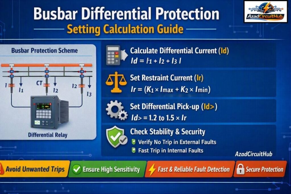
Table of Contents
Table of Contents
| Parameter | Typical consideration |
|---|---|
| Protection principle | Current differential |
| Main measurement | CT secondary currents |
| Protected zone | Busbar section |
| Main concern | Internal vs external fault discrimination |
| Important factor | CT saturation |
| Common relay type | Low-impedance or high-impedance differential |
| Trip speed | Typically very fast |
| Setting basis | Maximum through-fault current and CT performance |
What Is Busbar Differential Protection?
Busbar differential protection uses Kirchhoff’s Current Law as its basic operating principle. The sum of currents entering an electrical node should equal the sum of currents leaving it under normal operating conditions.
For a simplified busbar:
I₁ + I₂ + I₃ − I₄ = 0
When the bus is healthy, the differential current remains low. If a fault occurs inside the protected zone, the incoming and outgoing currents no longer balance, producing differential current that operates the relay.
A practical busbar differential system normally includes current transformers on each connected circuit. The CT secondary circuits are connected to the protection relay so that the relay can calculate the operating and restraint quantities.
The key objective of the busbar differential protection setting is to establish a stable operating point that separates internal faults from external faults.
Basic Busbar Differential Protection Setting Calculation
The calculation depends on the protection scheme and relay manufacturer, but the fundamental process is similar.
For a simple differential element, the differential current can be represented as:
Idiff = |ΣIin − ΣIout|
where:
- Idiff = differential or spill current
- Iin = currents entering the bus
- Iout = currents leaving the bus
For an ideal system during normal operation:
Idiff ≈ 0
In practice, CT ratio errors, relay measurement errors, wiring differences, and CT saturation produce some residual current. Therefore, the relay cannot normally be set to operate at an extremely small differential current.
A typical calculation starts by determining the maximum through-fault current. This is especially important for schemes that must remain stable when one or more CTs saturate during an external fault.
For a broader understanding of protection settings, check our guide on differential protection relay setting calculation to learn how relay parameters are determined and applied.
Example Busbar Differential Protection Setting Calculation
Consider a busbar with three connected feeders. Assume the CTs have a common secondary rating of 1 A and the maximum expected external fault current is 20 kA.
Suppose the maximum CT error and other uncertainties result in a calculated spill current of 0.12 A at the relay during the worst external fault.
A simplified security margin can then be applied.
| Calculation item | Value |
|---|---|
| Maximum external fault current | 20 kA |
| Calculated spill current | 0.12 A |
| Security factor | 1.5 |
| Minimum stable pickup | 0.18 A |
| Selected relay pickup | 0.20 A |
The final value must not be selected solely from this simplified example. The actual relay manual, CT characteristics, wiring resistance, maximum fault level, and protection philosophy must be considered.
This illustrates why busbar differential protection setting should be based on the complete protection system rather than a single relay parameter.
For faster preliminary checks, engineers can also use a Busbar Protection Calculator to organize CT ratios, fault current, relay pickup, and stability calculations before final relay coordination.
CT Ratio and Its Effect on Differential Protection
Current transformer selection has a direct effect on busbar differential protection performance.
If different CT ratios are installed on the circuits connected to the busbar, the relay must compensate for these ratios or the secondary currents must be matched through suitable protection arrangements.
For example:
| Circuit | Primary CT ratio | Secondary current at rated primary |
|---|---|---|
| Incomer | 2000/1 A | 1 A |
| Feeder 1 | 1000/1 A | 1 A |
| Feeder 2 | 1000/1 A | 1 A |
| Transformer | 1500/1 A | 1 A |
Modern numerical differential relays can generally compensate for CT ratio differences digitally. However, the engineer still needs to enter the correct CT data into the relay configuration.
Incorrect CT ratio settings can create a false differential current even when the busbar is healthy.
Low-Impedance vs High-Impedance Busbar Protection
Two common approaches are low-impedance and high-impedance differential protection.
| Feature | Low-impedance differential | High-impedance differential |
|---|---|---|
| CT arrangement | Flexible | Usually matched CTs preferred |
| CT saturation handling | Uses restraint and algorithms | Stability depends strongly on CT performance |
| Numerical relay use | Very common | Also available |
| Setting complexity | Moderate | Requires detailed CT calculations |
| Multiple bus sections | Well suited | More restrictive |
| Configuration flexibility | High | Lower |
Low-impedance schemes generally use percentage bias or restraint characteristics. The relay compares differential current against a restraint current.
A simplified operating condition can be expressed as:
Idiff > Ipickup + S × Irestraint
where S represents the selected bias slope.
The actual equation varies between relay manufacturers.
Need to verify relay protection settings? Explore our detailed differential protection relay setting calculation guide for practical calculations and setting considerations.
Percentage Bias and Restraint Setting
Percentage restraint is used to improve relay stability during heavy external faults.
During an external fault, CT saturation can cause the relay to see unequal currents. This creates spill current even though the fault is outside the protected bus zone.
A biased differential relay increases its operating threshold as restraint current increases.
| Setting | Purpose |
|---|---|
| Pickup current | Minimum differential current for operation |
| Bias slope | Improves security during through-faults |
| High-set element | Provides rapid operation for severe internal faults |
| Restraint current | Represents through-current magnitude |
| Stabilizing characteristic | Prevents unwanted trips |
A common engineering approach is to determine the maximum false differential current expected during the worst external fault and then select the slope and pickup with an appropriate safety margin.
The actual values should always follow the relay manufacturer’s application guide.
CT Saturation and Stability Calculation
CT saturation is one of the most important considerations when calculating busbar differential settings.
During a high-current external fault, the CT carrying the fault current may saturate. Its secondary current can then become lower or distorted compared with the actual primary current.
This creates an artificial differential current.
The worst-case condition should therefore be considered when checking stability.
Important CT parameters include:
- CT ratio
- Accuracy class
- Knee-point voltage
- Secondary winding resistance
- Lead resistance
- Burden
- Maximum through-fault current
- CT remanence
- X/R ratio of the fault
For high-impedance protection, the stabilizing resistor and CT knee-point voltage are particularly important.
A simplified high-impedance stability relationship is often assessed using the maximum through-fault current and the resistance of the CT and secondary circuit.
The exact calculation should follow the selected relay and protection scheme manufacturer’s recommended method.
High-Set Differential Element
Many numerical busbar relays provide a high-set differential element in addition to the normal biased differential characteristic.
The high-set element can provide extremely fast operation for severe internal faults. However, it must remain secure for the maximum external fault and CT transient conditions.
| Element | Main function |
|---|---|
| Low-set differential | Sensitive internal fault detection |
| Biased differential | Stability during high through-current |
| High-set differential | Fast operation for severe internal faults |
| Check zone | Helps verify genuine busbar faults |
The high-set value should be checked against the maximum possible external fault current referred to the relay secondary.
This is another area where a Busbar Protection Calculator can help organize the fault current and CT ratio calculations before entering values into the protection relay.
Check Zone Protection
Modern busbar protection systems may use a check zone as an additional security measure.
The main protection divides the switchyard into individual protection zones. The check zone provides an independent confirmation that a fault is associated with the busbar system.
This arrangement can reduce the risk of incorrect tripping caused by CT wiring problems, isolator status errors, or incorrect zone selection.
A typical busbar scheme may include:
- Main differential protection
- Check zone differential protection
- CT supervision
- Breaker failure protection
- Isolator position logic
- Trip circuit supervision
These functions work together to provide dependable busbar fault clearing.
Worked Setting Example
Assume a numerical relay has the following preliminary requirements:
| Parameter | Example value |
|---|---|
| CT secondary | 1 A |
| Maximum external fault | 25 kA |
| Maximum calculated spill current | 0.15 A |
| Security multiplier | 1.5 |
| Preliminary pickup | 0.225 A |
| Selected pickup | 0.25 A |
| Bias slope | Relay-specific |
| High-set element | Based on external-fault stability |
The preliminary pickup can be estimated as:
Ipickup = Spill Current × Security Factor
Ipickup = 0.15 × 1.5 = 0.225 A
A practical relay setting could therefore be selected above this value, such as 0.25 A, provided it satisfies the relay manufacturer’s recommended setting range and the overall protection coordination study.
This is only an illustrative calculation. A real project requires complete CT saturation and fault-level analysis before the setting is approved.
Factors That Affect the Final Setting
Several factors influence the final busbar differential protection setting.
| Factor | Effect on setting |
|---|---|
| Maximum fault current | Determines through-fault stress |
| CT ratio | Changes relay secondary current |
| CT knee-point voltage | Affects saturation performance |
| CT secondary resistance | Influences stability |
| Cable lead resistance | Adds CT circuit burden |
| Relay accuracy | Contributes to measurement error |
| Bias slope | Improves external fault stability |
| Bus configuration | Changes protection zones |
| Fault level | Determines required stability |
| Earthing arrangement | Influences fault current |
The maximum internal fault current should also be considered when checking protection sensitivity. A setting that is unnecessarily high can reduce the relay’s ability to detect lower-current internal faults.
Busbar Protection Testing and Commissioning
After calculating the settings, the protection system should be tested before being placed into service.
Typical commissioning checks include:
- CT ratio verification
- CT polarity testing
- Secondary injection testing
- Relay pickup verification
- Differential characteristic testing
- Bias slope verification
- Trip output testing
- Zone selection verification
- Breaker trip circuit testing
- Check zone testing
- Isolator logic testing
CT polarity is particularly important. A reversed CT can produce a differential current under normal load and may cause unwanted operation.
The commissioning team should also verify the relay configuration against the approved protection setting sheet.
Common Mistakes in Differential Protection Settings
Several errors can compromise busbar protection performance.
Using only the nominal fault current
The maximum prospective fault current should be determined from the latest short-circuit study. Using an outdated fault level can lead to inadequate stability.
Ignoring CT saturation
CT saturation is a major source of false differential current during external faults. It should be included in the stability assessment.
Entering incorrect CT ratios
The relay configuration must match the actual installed CT ratios and wiring arrangement.
Selecting excessive pickup
A very high pickup improves security but can reduce sensitivity to lower-current internal faults.
Forgetting zone selection logic
Busbar schemes depend heavily on correct circuit-breaker and disconnector status information. Incorrect zone logic can result in overtripping or failure to trip.
Final Busbar Differential Protection Setting Checklist
Before approving a setting calculation, verify the following:
| Check | Status |
|---|---|
| Latest short-circuit study available | ✓ |
| CT ratios verified | ✓ |
| CT polarity confirmed | ✓ |
| CT saturation checked | ✓ |
| Maximum external fault assessed | ✓ |
| Differential pickup calculated | ✓ |
| Bias slope selected | ✓ |
| High-set element checked | ✓ |
| Check zone logic verified | ✓ |
| Relay settings independently reviewed | ✓ |
| Secondary injection completed | ✓ |
For a quick preliminary assessment, engineers can use a Busbar Protection Calculator to simplify current, CT ratio, differential pickup, and related protection calculations.
FAQs About Busbar Differential Protection
What is the main purpose of busbar differential protection?
Its main purpose is to detect faults within a defined busbar zone and disconnect the affected section as quickly as possible. It also needs to remain stable during external faults.
How is differential current calculated?
Differential current is generally obtained from the vector sum of the CT currents connected to the protected zone. In an ideal healthy condition, the sum is close to zero.
Why is CT saturation important?
CT saturation can cause unequal secondary currents during an external fault. The resulting spill current can appear like an internal fault, so CT performance must be included in the stability calculation.
What is percentage bias in a differential relay?
Percentage bias increases the relay operating threshold as current through the protected zone increases. This improves stability during heavy external faults while maintaining sensitivity to internal faults.
Can busbar differential protection settings be calculated manually?
Yes. Preliminary calculations can be performed manually using CT ratios, maximum fault current, CT characteristics, spill current, and relay characteristics. However, final settings should be checked against the relay manufacturer’s application requirements and the complete protection study.
Conclusion
A properly designed busbar differential scheme must balance sensitivity, speed, and security. The calculation begins with the maximum through-fault current and CT characteristics, followed by an assessment of CT errors, saturation, relay pickup, restraint slope, and high-set operation.
The correct busbar differential protection setting cannot be selected from a generic value because every installation has different CTs, fault levels, bus configurations, and relay characteristics. Engineers should therefore verify the final values through a detailed protection coordination and stability study.
When used correctly, differential protection provides fast and selective fault clearance while minimizing unnecessary interruption to healthy parts of the electrical system.
Get new guides in your feed. Follow Electrical Insights on LinkedIn for new electrical standards guides, calculators and design tips from Azad Circuit Hub.
#BusbarDifferentialProtection, #DifferentialProtection, #BusbarProtection, #ProtectionRelay, #RelaySettings, #CTRatio, #ElectricalProtection, #PowerSystemProtection, #SubstationProtection, #ProtectionEngineering
