Busbar Zone Protection: Check Zone vs Discriminating Zone
Busbar Zone Protection is designed to detect faults on a switchboard or busbar and disconnect the affected section as quickly as possible. A busbar fault can involve very high fault current because several incoming and outgoing circuits may feed the same fault. Fast and selective protection is therefore important for limiting equipment damage and maintaining system stability.
Modern busbar protection schemes commonly use two measuring zones: the discriminating zone and the check zone. Both use current transformer signals, but they perform different functions. Understanding how these zones work helps engineers review protection logic, CT arrangements, relay settings, and circuit breaker trip commands.
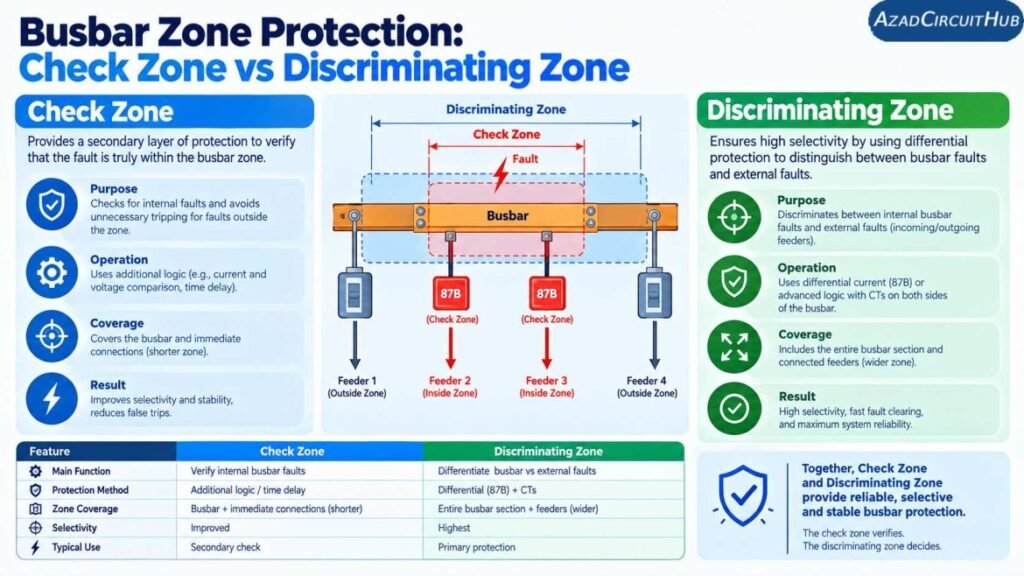
Table of Contents
Table of Contents
Check Zone vs Discriminating Zone
The basic difference is that the discriminating zone identifies which bus section contains the fault, while the check zone provides an additional security check before a busbar trip is issued.
| Feature | Discriminating Zone | Check Zone |
|---|---|---|
| Main purpose | Identifies the faulty bus section | Confirms that a busbar fault exists |
| Coverage | Individual bus sections | Usually covers a wider bus area |
| Selectivity | High | Lower |
| Primary role | Fault discrimination | Security and supervision |
| Typical input | Selected CTs associated with a bus section | Wider set of CT inputs |
| Trip decision | Determines the affected zone | Supervises the trip |
| Main benefit | Selective isolation | Prevents unwanted bus trips |
This arrangement allows the protection system to combine sensitivity with security. The discriminating zone provides fault location, while the check zone helps prevent an incorrect trip caused by CT errors, wiring problems, isolator status errors, or other abnormal conditions.
What Is a Discriminating Zone?
A discriminating zone is the part of the busbar protection scheme used to determine which specific bus section contains the fault.
For example, consider a switchboard divided into Bus Section A and Bus Section B. Each section may have several feeders, an incomer, and a bus coupler. The protection relay receives current signals from the CTs connected to these circuits.
When a fault occurs within one section, the relay compares the currents entering and leaving that particular zone. Under normal load or an external fault, the current balance should remain approximately correct. During an internal busbar fault, the balance changes significantly.
A simplified differential relationship is:
I_diff = |ΣI_in − ΣI_out|
Where:
- I_diff = differential current
- ΣI_in = sum of currents entering the protected zone
- ΣI_out = sum of currents leaving the protected zone
If the differential current exceeds the protection threshold and the zone logic confirms the fault, the relay can issue a trip command to the relevant circuit breakers.
For engineers working on protection settings, a Busbar Protection Calculator can also be useful for checking key busbar protection and fault-current parameters.
What Is a Check Zone?
The check zone is an additional protection zone that normally covers a wider portion of the busbar arrangement. Its main purpose is security.
A check zone does not usually determine the exact bus section that must be disconnected. Instead, it confirms that the overall current balance indicates a genuine busbar fault.
The concept can be simplified as:
Trip = Discriminating Zone Fault + Check Zone Fault
This logic means that a trip requires both the local zone protection and the wider check-zone protection to indicate a fault, depending on the specific relay manufacturer’s scheme.
The check zone is particularly useful where incorrect isolator status, CT circuit problems, or switching operations could otherwise cause an unwanted busbar trip.
Why Two Zones Are Used
Busbar protection must balance two important requirements:
- High sensitivity to internal faults.
- High security against unwanted operation.
A very sensitive differential scheme can detect low-level faults quickly, but the protection system must also tolerate external faults and measurement errors.
CT saturation is an important consideration. During a high-current external fault, one CT may saturate before another. This can create an apparent differential current even though the fault is outside the protected bus zone.
The check zone provides another layer of supervision against this type of incorrect operation.
| Protection Concern | Discriminating Zone | Check Zone |
|---|---|---|
| Fault location | Primary function | Secondary confirmation |
| Internal bus fault | Detects it | Confirms it |
| External fault | Should remain stable | Helps maintain security |
| CT saturation | Must be considered | Adds security |
| Isolator position | Can affect zone selection | Provides wider supervision |
| Selective tripping | Essential | Supervisory role |
Busbar Zone Protection and CT Arrangement
Current transformers are central to any differential busbar protection scheme. The protection relay relies on accurate CT signals to calculate the current balance within each zone.
Incorrect CT polarity, ratio mismatch, wiring errors, or CT saturation can affect differential protection performance.
For example, if an incomer CT is connected with incorrect polarity, the relay may see current in the wrong direction. This can produce an unwanted differential quantity during normal operating conditions or an external fault.
Before commissioning, engineers normally verify:
- CT ratio
- CT polarity
- CT secondary wiring
- CT class and burden
- Phase identification
- Relay input configuration
- Isolator status inputs
- Trip circuit wiring
- Circuit breaker feedback
- Zone selection logic
A Busbar Protection Calculator can complement these checks when reviewing current values, differential settings, and related protection calculations.
Check Zone Logic During Busbar Faults
Consider a double-bus switchboard with several feeders and two bus sections.
If a fault occurs inside Bus Section A, the discriminating zone associated with Section A should detect the differential current. The check zone should also confirm that the overall bus arrangement has an internal fault.
The protection system can then trip only the breakers required to isolate Section A.
| Fault Location | Discriminating Zone | Check Zone | Typical Action |
|---|---|---|---|
| Bus Section A internal fault | Operates | Operates | Trip Section A |
| Bus Section B internal fault | Operates | Operates | Trip Section B |
| Feeder external fault | Stable | Stable | Feeder protection trips |
| Transformer external fault | Stable | Stable | Transformer protection operates |
| CT circuit abnormality | May be affected | Provides security depending on scheme | Alarm/blocking logic may apply |
The exact logic varies between manufacturers and switchgear configurations, so the relay application manual and approved protection design should always be followed.
Importance of Isolator Status
In many busbar protection systems, disconnectors or isolators determine which physical bus section a feeder belongs to.
The relay uses auxiliary contacts from these devices to establish the protection zone associated with each circuit.
If an isolator changes position, the protection logic may automatically change the CT contribution assigned to a particular zone.
This is one reason busbar protection commissioning requires more than checking relay settings. The physical switching arrangement and protection logic must agree.
For larger substations, reviewing the complete protection arrangement with a Busbar Protection Calculator can help organize the electrical values used during design and verification.
Check Zone and Discriminating Zone in Practical Protection Design
The two-zone concept is particularly useful in complex substations where several circuits share common busbars.
A well-designed scheme should provide:
- Fast internal fault detection
- Selective circuit breaker tripping
- Security during external faults
- Reliable CT inputs
- Correct bus section identification
- Suitable CT saturation performance
- Secure trip logic
- Clear alarm and blocking functions
High-speed busbar protection is often applied because a bus fault can expose several connected circuits to high fault current at the same time.
The actual operating time depends on the relay, CT performance, breaker operating time, communication architecture, and protection scheme.
Common Busbar Protection Mistakes
Several issues can reduce the reliability of a busbar differential scheme.
Incorrect CT polarity
A polarity error can produce a false differential current. CT polarity should be checked during commissioning rather than assumed from drawings alone.
Incorrect zone assignment
In double-bus or transfer-bus arrangements, incorrect isolator status signals can assign a circuit to the wrong protection zone.
Poor CT performance
CT saturation during external faults can create unwanted differential current. CT selection must therefore match the protection application.
Incomplete trip logic testing
Testing the relay pickup alone is not enough. The complete chain from CT input to relay logic, breaker trip coil, breaker auxiliary contacts, and alarm indication should be verified.
Frequently Asked Questions
What is Busbar Zone Protection?
Busbar Zone Protection is a protection arrangement that detects electrical faults within defined busbar sections and trips the appropriate circuit breakers to isolate the fault rapidly.
What is the difference between a check zone and a discriminating zone?
The discriminating zone identifies the specific bus section where the fault has occurred. The check zone provides wider supervision and confirms that the conditions are consistent with an internal busbar fault.
Why is a check zone used in differential protection?
A check zone improves security. It can help prevent unwanted busbar tripping caused by CT saturation, incorrect zone selection, switching information errors, or other abnormal conditions.
What causes busbar differential protection to trip incorrectly?
Possible causes include incorrect CT polarity, CT saturation, wiring errors, incorrect CT ratios, faulty isolator status signals, relay configuration errors, and commissioning problems.
Is busbar differential protection faster than feeder protection?
Busbar differential protection is specifically designed for rapid detection of faults within its protected zone. Its actual operating time depends on the relay, CTs, logic, breaker, and overall protection scheme. Coordination with feeder and transformer protection remains necessary.
Final Takeaway
Busbar Zone Protection relies on accurate current measurement, correct zone definition, and secure trip logic. The discriminating zone provides the selective fault location, while the check zone adds an important layer of security.
For simple bus arrangements, the protection logic may be relatively straightforward. For double-bus, sectionalized, or transfer-bus systems, CT selection, isolator status, zone assignment, and relay logic require careful engineering and commissioning.
The key is to treat the check zone and discriminating zone as complementary parts of the same protection philosophy rather than competing protection methods. When correctly designed and tested, the arrangement can provide fast internal fault clearing while reducing the risk of unnecessary busbar outages.
Get new guides in your feed. Follow Electrical Insights on LinkedIn for new electrical standards guides, calculators and design tips from Azad Circuit Hub.
#BusbarZoneProtection, #CheckZone, #DiscriminatingZone, #BusbarProtection, #ElectricalProtection, #ProtectionRelay, #DifferentialProtection, #PowerSystemProtection, #SwitchgearProtection, #ElectricalEngineering