Common Busbar Sizing Mistakes to Avoid
Common Busbar Sizing Mistakes can lead to excessive heating, voltage drop, nuisance trips, insulation damage, and even serious electrical faults inside switchboards and distribution panels. A busbar may look simple, but its size depends on more than the connected load.
In industrial panels, busbar selection should consider continuous current, short-circuit withstand, material, temperature rise, enclosure conditions, installation arrangement, and applicable standards. A correct calculation also helps maintain safe clearances and reliable connections.
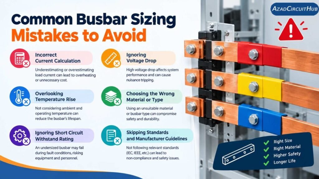
Table of Contents
Table of Contents
The table below summarizes some frequent errors and their practical consequences.
| Busbar Sizing Mistake | Possible Result | Better Practice |
|---|---|---|
| Selecting only from load current | Overheating | Check continuous current and temperature rise |
| Ignoring short-circuit current | Mechanical or thermal damage | Verify short-circuit withstand |
| Using only width and thickness | Incorrect capacity | Consider material, orientation, and installation |
| Ignoring ambient temperature | Excessive temperature | Apply appropriate derating |
| Poor joint design | Hot spots | Check joints, torque, and contact area |
| No allowance for future load | Early replacement | Include a suitable design margin |
| Ignoring enclosure ventilation | Higher operating temperature | Review heat dissipation |
| Using unsuitable material | Higher losses or corrosion | Select appropriate copper or aluminium |
1. Sizing the Busbar Only From Load Current
One of the most common busbar sizing mistakes is selecting a bar simply because its calculated ampacity is slightly above the load current.
For example, a panel with a calculated current of 420 A should not automatically receive a busbar rated for exactly 420 A. Actual operating conditions can be different from the assumptions used during the initial calculation.
Continuous loading, ambient temperature, enclosure temperature, bar arrangement, and ventilation can all affect the final temperature.
A practical design should verify the required current rating under the actual installation conditions rather than relying on a single ampacity value.
2. Ignoring Short-Circuit Withstand
Normal operating current is only part of busbar design. During a short circuit, the busbar can experience extremely high current for a short period.
This produces both thermal and electrodynamic forces. Closely spaced parallel bars can experience strong mechanical forces that may bend supports, loosen connections, or damage insulation.
| Parameter | What It Checks |
|---|---|
| Normal current | Continuous operating capacity |
| Short-time withstand current | Thermal stress during a fault |
| Peak withstand current | Electrodynamic forces |
| Fault duration | Energy deposited during the fault |
| Support spacing | Mechanical resistance |
A busbar system should therefore be checked against the prospective short-circuit current and the protection clearing time.
3. Treating Copper and Aluminium as the Same
Copper and aluminium have different electrical and physical properties. A copper busbar and an aluminium busbar with identical dimensions will not have the same electrical performance.
Aluminium generally has higher electrical resistivity than copper, so a larger cross-sectional area may be required for an equivalent current-carrying requirement.
Material also affects weight, cost, joint design, oxidation behavior, and termination requirements.
When comparing busbar materials, consider:
- Electrical conductivity
- Cross-sectional area
- Temperature rise
- Mechanical strength
- Weight
- Joint construction
- Surface treatment
- Installation environment
For practical panel design, material selection should be made before finalizing the busbar dimensions.
4. Ignoring Ambient Temperature and Enclosure Heating
Another important issue is assuming that the busbar operates at the same temperature as the surrounding room.
A metal enclosure containing breakers, contactors, transformers, drives, and cables can become significantly warmer than ambient air. Heat generated by the busbar itself adds to this temperature.
This becomes particularly important in compact switchboards where natural ventilation is limited.
Before selecting the busbar, consider the panel’s:
- Ambient temperature
- Internal heat generation
- Ventilation
- Enclosure size
- Number of current-carrying conductors
- Busbar arrangement
- Duty cycle
These factors can change the allowable continuous current.
5. Using a Generic Busbar Table Without Checking the Installation
Busbar tables are useful for preliminary design, but they should not be treated as universal values.
A copper bar measuring 50 × 10 mm has a cross-sectional area of 500 mm², but its actual current capacity depends on how it is installed and cooled.
The same cross-sectional area can have different performance depending on whether the bar is installed edge-on, flat, enclosed, ventilated, or arranged beside other bars.
Before using a published table, check what conditions were used to establish the rating.
A quick preliminary calculation can be made with our busbar size calculator before verifying the result against the applicable standard and manufacturer’s data.
6. Forgetting Busbar Joints and Connection Points
The busbar itself may have adequate capacity while the connection becomes the hottest part of the assembly.
Loose bolts, poor surface preparation, inadequate contact pressure, undersized lugs, and contamination can increase contact resistance. Even a small resistance at a high-current joint can produce substantial localized heating.
| Joint Problem | Typical Effect |
|---|---|
| Loose connection | Increased contact resistance |
| Small contact area | Localized heating |
| Incorrect torque | Unreliable connection |
| Oxidized surface | Poor electrical contact |
| Uneven clamping | Hot spots |
| Undersized hardware | Mechanical and thermal problems |
Proper torque, suitable hardware, adequate contact area, and appropriate surface preparation are essential for reliable busbar joints.
7. Not Considering Future Load Growth
Panel loads often increase after commissioning. Additional motors, pumps, drives, feeders, or process equipment may be added later.
Sizing a busbar exactly for today’s calculated load can make future modifications difficult.
However, adding a large arbitrary margin is also not good engineering practice because it can increase cost and physical size without a clear benefit.
The design margin should reflect the expected operating conditions, project requirements, and future expansion plans.
8. Incorrect Phase and Neutral Busbar Selection
Another area often overlooked is the neutral conductor or neutral busbar.
In a balanced three-phase linear load, neutral current can be relatively low. However, nonlinear loads such as variable frequency drives, switched-mode power supplies, computers, LED drivers, and other electronic equipment can produce harmonic currents.
Triplen harmonics can accumulate in the neutral system.
Therefore, neutral busbar sizing should consider the actual load characteristics rather than automatically assuming that the neutral can always be smaller than the phase busbars.
9. Poor Busbar Layout and Clearance
Correct cross-sectional area does not guarantee a safe busbar system.
The physical layout must provide adequate phase-to-phase and phase-to-earth clearance according to the applicable standard and system voltage. Insulating supports must also withstand the mechanical forces generated during faults.
Good layout practice includes:
- Short and direct current paths
- Secure supports
- Adequate electrical clearances
- Appropriate creepage distances
- Protected connections
- Easy inspection access
- Proper phase identification
The arrangement should also allow maintenance technicians to inspect and tighten connections safely.
For an initial conductor-area check before detailed layout work, the busbar size calculator can help establish a suitable starting point.
10. Failing to Check Voltage Drop and Power Loss
Voltage drop is often more important in long busbar systems and high-current distribution arrangements.
Resistance causes power loss according to:
P = I²R
As current increases, losses increase rapidly. A small increase in resistance can therefore produce additional heat.
For most short panel busbars, voltage drop may be small. However, longer busduct sections and high-current distribution systems require a more detailed evaluation.
How to Avoid Common Busbar Sizing Mistakes
A reliable busbar design should follow a structured process rather than selecting dimensions from habit.
| Design Step | Check |
|---|---|
| 1 | Determine maximum continuous current |
| 2 | Select copper or aluminium |
| 3 | Establish preliminary cross-sectional area |
| 4 | Check temperature rise |
| 5 | Apply installation and ambient conditions |
| 6 | Verify short-circuit withstand |
| 7 | Check mechanical supports |
| 8 | Design reliable joints |
| 9 | Verify clearances and creepage |
| 10 | Confirm applicable standards |
Using this sequence reduces the risk of missing an important design parameter. The busbar size calculator is useful for the initial sizing stage, while final design verification should use project specifications, manufacturer data, and the governing electrical standard.
Frequently Asked Questions
What is the most common busbar sizing mistake?
Selecting a busbar based only on the calculated load current is one of the most common errors. Temperature rise, installation conditions, short-circuit forces, joints, and enclosure heating also need to be considered.
How do I calculate busbar size?
Start with the required continuous current and select the conductor material. Then determine a suitable cross-sectional area and verify temperature rise, installation conditions, short-circuit withstand, mechanical support, and applicable standards.
Does busbar size depend on short-circuit current?
Yes. Short-circuit current can create severe thermal and mechanical stress. The busbar and its supports must be capable of withstanding the expected fault current for the required clearing time.
Is a larger busbar always better?
Not necessarily. A larger busbar can reduce resistance and heating, but it may increase cost, weight, enclosure size, and connection requirements. The design should be based on the actual electrical and mechanical requirements.
Should the neutral busbar be the same size as the phase busbars?
It depends on the load. Harmonic currents from nonlinear loads can significantly affect neutral current. The neutral busbar should therefore be sized according to the actual system characteristics and applicable design requirements.
Final Checks Before Selecting a Busbar
Avoiding Common Busbar Sizing Mistakes requires more than matching a current value to a bar dimension. The complete design should consider current capacity, conductor material, temperature rise, short-circuit withstand, mechanical forces, joints, clearances, ventilation, harmonics, and future expansion.
A good workflow starts with a preliminary busbar calculation and then verifies the result using the relevant electrical standard and manufacturer information. This approach provides a stronger basis for designing reliable switchboards, MCC panels, distribution boards, and industrial power systems.
Get new guides in your feed. Follow Electrical Insights on LinkedIn for new electrical standards guides, calculators and design tips from Azad Circuit Hub.
#BusbarSizing, #BusbarDesign, #CommonBusbarSizingMistakes, #ElectricalEngineering, #ElectricalDesign, #BusbarAmpacity, #Switchgear, #PowerDistribution, #ShortCircuitRating, #ElectricalSafety