
How to Size a Neutral Busbar: Formula, Chart and Practical Examples
Neutral busbar sizing is an important step in designing distribution boards, switchgear, and industrial electrical panels. The neutral carries the return current from single-phase loads and may carry significant harmonic current in three-phase systems. Choosing the correct size helps prevent overheating, insulation damage, and equipment failure.
How to Size a Neutral Busbar: Quick Checks
| Design Parameter | What to Check |
|---|---|
| Neutral current | Maximum expected continuous current |
| Busbar material | Copper or aluminum |
| Cross-sectional area | Width × thickness |
| Harmonic current | Third-harmonic and other triplen components |
| Temperature rise | Ambient temperature and enclosure conditions |
| Short-circuit withstand | Fault current and clearing time |
| Applicable standard | IEC 61439, NEC, and local requirements |
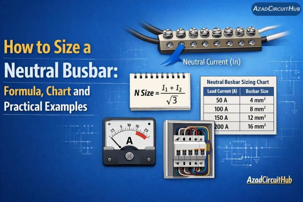
Table of Contents
Table of Contents
What Is a Neutral Busbar?
A neutral busbar is a conductive bar that provides a common connection point for neutral conductors in an electrical panel. It connects to the source neutral as required by the system design and distributes neutral connections to outgoing circuits.
In a three-phase, four-wire system, neutral current depends on phase-load imbalance and harmonic content. Therefore, the neutral busbar should not automatically be rated at half the phase busbar capacity.
How to Size a Neutral Busbar: Step by Step
To size a neutral busbar, calculate the maximum expected neutral current, estimate the required cross-sectional area, and verify the thermal and short-circuit ratings.
Step 1: Calculate the Neutral Current
For a three-phase system, the fundamental-frequency neutral current is the vector sum of the three phase currents.
Formula for WordPress:
I_N = |I_A + I_B + I_C|
Where:
I_N= neutral current in amperesI_A= phase A current phasorI_B= phase B current phasorI_C= phase C current phasor
The currents must be treated as phasors, including their phase angles. Adding the three current magnitudes directly will not give the correct result.
Balanced linear loads may produce very little fundamental neutral current. However, computers, LED drivers, and other nonlinear loads can generate third-harmonic currents that add in the neutral.
When assessing feeder loads, also check your 3 phase cable size calculator to compare conductor sizing requirements with the panel’s expected load.
Step 2: Calculate the Required Busbar Area
A preliminary cross-sectional area can be estimated using current density.
Formula:
A = I_N / J
Where:
A= busbar cross-sectional area in mm²I_N= design neutral current in amperesJ= selected current density in A/mm²
For example, assume a design neutral current of 200 A and a preliminary current density of 1.2 A/mm².
A = 200 / 1.2
A = 166.7 mm²
A copper busbar measuring 30 mm × 6 mm provides:
A = 30 × 6 = 180 mm²
This meets the preliminary area estimate. However, it does not automatically establish a safe 200 A continuous rating. The final selection must be verified against temperature-rise limits, enclosure conditions, mounting arrangements, and manufacturer data.
Use the bus bar size calculator for preliminary dimensional comparisons.
Neutral Busbar Size Chart
The following chart uses an illustrative current density of 1.2 A/mm². These are preliminary area estimates, not certified ampacity ratings.
| Neutral Current | Calculated Area | Example Copper Busbar | Actual Area |
|---|---|---|---|
| 50 A | 41.7 mm² | 25 × 2 mm | 50 mm² |
| 100 A | 83.3 mm² | 25 × 4 mm | 100 mm² |
| 150 A | 125 mm² | 25 × 6 mm | 150 mm² |
| 200 A | 166.7 mm² | 30 × 6 mm | 180 mm² |
| 250 A | 208.3 mm² | 40 × 6 mm | 240 mm² |
| 300 A | 250 mm² | 50 × 5 mm | 250 mm² |
| 400 A | 333.3 mm² | 50 × 8 mm | 400 mm² |
Actual capacity varies with ventilation, bar orientation, spacing, joint resistance, and enclosure temperature. Always use validated manufacturer data for the final rating.
Should the Neutral Busbar Match the Phase Busbar?
The answer depends on the load profile and applicable electrical requirements. A reduced neutral may be permitted in some installations, but a full-size neutral is often a sensible starting point when nonlinear loads are present or their harmonic content is unknown.
| Load Type | Neutral Sizing Consideration |
|---|---|
| Balanced linear loads | Fundamental neutral current may be low |
| Unbalanced single-phase loads | Calculate the neutral current |
| Computer equipment | Assess triplen harmonics |
| LED lighting | Check harmonic distortion |
| Variable-frequency drives | Review the system configuration |
| Mixed commercial loads | Assess imbalance and harmonics |
Never reduce the neutral solely because the three phase currents appear balanced. Harmonic currents can still produce substantial neutral loading.
For a related conductor selection check, consult your cable size calculator and verify that the neutral and phase conductors meet the applicable design requirements.
Copper vs. Aluminum Neutral Busbars
Copper has higher electrical conductivity than aluminum for the same cross-sectional area. Aluminum is lighter and may cost less, but a larger area is generally needed to achieve comparable resistance.
| Property | Copper | Aluminum |
|---|---|---|
| Conductivity | Higher | Lower |
| Weight | Higher | Lower |
| Area for comparable resistance | Generally smaller | Generally larger |
| Joint requirements | Correct torque and clean contact surfaces | Compatible hardware and oxidation control |
| Final current rating | Verify manufacturer data | Verify manufacturer data |
Do not apply the same current-density assumption to both materials without checking the design basis.
Temperature Rise and Short-Circuit Checks
A busbar can have sufficient area for normal current yet overheat under poor ventilation or high fault current. Before approving the design, check:
- Ambient temperature inside the panel.
- Busbar spacing and mounting orientation.
- Joint resistance and terminal torque.
- Insulation and support temperature ratings.
- Prospective short-circuit current and clearing time.
- Mechanical forces during a fault.
IEC 61439 is relevant to many low-voltage switchgear and controlgear assemblies. The applicable requirements depend on the assembly and installation. Where a fault may involve earth leakage, review the appropriate earth fault relay setting calculation guide as part of the protection design. An earth fault relay does not replace short-circuit withstand verification.
For another preliminary sizing reference, use the busbar size calculator alongside verified manufacturer ratings.
Expert Note: Practical Busbar Design
In practical panel design and troubleshooting, neutral busbar problems often trace back to underestimated harmonic loads, loose joints, or poor heat dissipation. I check the expected load profile, termination quality, and enclosure conditions before approving a neutral rating.
Common Neutral Busbar Sizing Mistakes
Avoid these errors when designing an electrical panel:
- Assuming the neutral always carries zero current.
- Selecting the busbar using current density alone.
- Ignoring third-harmonic currents.
- Applying copper ratings directly to aluminum.
- Overlooking short-circuit forces and support spacing.
- Treating a preliminary chart as a certified ampacity table.
For additional design checks, the busbar size calculation reference can help compare busbar dimensions before the final thermal and fault verification.
Frequently Asked Questions
1. Should a neutral busbar be the same size as the phase busbar?
Not always. Its size depends on the expected neutral current, harmonic content, applicable code, and verified assembly rating. A full-size neutral is a useful starting point when the load profile is uncertain.
2. How do you calculate neutral busbar size?
Calculate the maximum expected neutral current, estimate the cross-sectional area using A = I_N / J, and verify continuous current capacity, temperature rise, and short-circuit withstand using manufacturer data or assembly verification.
3. Can a neutral busbar be smaller than the phase busbar?
It may be permitted in some designs, but only when the applicable requirements allow it and the calculated neutral current supports the reduction. Harmonics must be considered.
4. Why does a neutral busbar overheat?
Common causes include excessive neutral current, triplen harmonics, loose connections, poor contact surfaces, inadequate ventilation, and undersized busbars. Inspect and test the panel safely before selecting corrective action.
5. Which standard applies to neutral busbar sizing?
IEC 61439 applies to many low-voltage switchgear and controlgear assemblies. In the United States, applicable NEC provisions and product standards may also govern the installation. Requirements depend on the equipment and jurisdiction.
Conclusion
Correct neutral busbar sizing begins with the expected neutral current, not an arbitrary percentage of the phase busbar rating. Calculate the load, assess harmonic content, select the material and cross-sectional area, and verify temperature rise and short-circuit performance.
Use preliminary calculations together with manufacturer data, applicable standards, and verified assembly ratings to support safe and reliable electrical distribution.
Get new guides in your feed. Follow Electrical Insights on LinkedIn for new electrical standards guides, calculators and design tips from Azad Circuit Hub.
#NeutralBusbarSizing, #NeutralBusbar, #BusbarSizing, #ElectricalEngineering, #ElectricalPanelDesign, #NeutralWireSizing, #LoadCalculation, #PowerDistribution, #ElectricalDesign, #BusbarCalculation
