
Busbar Ampacity Chart by Cross-Sectional Area: Sizing, Shapes and Current Capacity
Choosing the right busbar is important for safe and reliable power distribution. A busbar that is too small can overheat, while an oversized conductor increases material cost and takes up more panel space. The correct selection depends on cross-sectional area, conductor material, allowable temperature rise, installation conditions, and busbar shape.
The following busbar ampacity chart provides practical reference values for copper and aluminum busbars under typical electrical panel conditions. Actual ratings should always be verified against the applicable IEC, NEC, manufacturer, or project standard.
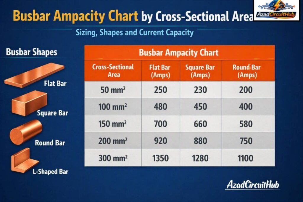
Table of Contents
Table of Contents
Busbar Ampacity Chart by Cross-Sectional Area
The table below gives approximate continuous current capacities for common copper and aluminum busbar sizes. These values are reference figures rather than universal ratings because heat dissipation varies with enclosure design, orientation, spacing, and ambient temperature.
| Cross-Sectional Area | Typical Copper Ampacity | Typical Aluminum Ampacity | Common Application |
|---|---|---|---|
| 10 mm² | 45–55 A | 35–45 A | Small distribution circuits |
| 20 mm² | 75–90 A | 55–70 A | Control and distribution panels |
| 30 mm² | 105–125 A | 80–95 A | Small switchboards |
| 40 mm² | 135–155 A | 100–120 A | Distribution boards |
| 50 mm² | 165–190 A | 125–145 A | Panel busbars |
| 75 mm² | 235–270 A | 175–205 A | Main distribution |
| 100 mm² | 300–340 A | 225–260 A | Switchgear |
| 150 mm² | 420–475 A | 315–365 A | Main bus systems |
| 200 mm² | 530–600 A | 395–460 A | Industrial switchboards |
| 300 mm² | 700–790 A | 525–610 A | High-current distribution |
| 400 mm² | 850–950 A | 640–735 A | Large switchgear |
These ranges can change considerably with installation conditions. For example, a 50 mm² copper busbar installed in free air may carry more current than the same cross-sectional area enclosed inside a compact switchboard.
For a project-specific calculation, a bus bar ampacity calculator can help estimate current capacity from material, dimensions, temperature rise, and installation conditions before selecting the final busbar.
What Determines Busbar Ampacity?
Ampacity is the maximum current a conductor can carry continuously without exceeding its permitted temperature. Cross-sectional area is important, but it is only one part of the calculation.
The main factors affecting busbar current capacity include:
- Copper or aluminum material
- Width and thickness
- Surface area
- Ambient temperature
- Permitted temperature rise
- Busbar orientation
- Enclosure ventilation
- Number of adjacent bars
- Phase spacing
- AC or DC operation
- Frequency and skin effect
- Connection and joint temperature
- Short-circuit withstand requirements
A busbar with a larger exposed surface can transfer heat to the surrounding air more effectively. This is one reason flat bars can provide useful thermal performance compared with conductors having the same metal cross-sectional area but different geometry.
Busbar Shapes Sizing and Current Capacity
Busbar shapes sizing involves more than simply calculating width multiplied by thickness. The physical shape affects heat dissipation, mechanical strength, installation space, and electrical performance.
The most common busbar profiles are flat, tubular, and rectangular.
| Busbar Shape | Typical Advantage | Typical Use |
|---|---|---|
| Flat bar | Simple installation and good surface area | Distribution panels |
| Rectangular bar | High current capacity and compact arrangement | Switchboards |
| Tubular bar | Good mechanical strength and cooling | High-current systems |
| Laminated bar | Low impedance and compact construction | Power electronics |
| Flexible busbar | Easy routing and vibration tolerance | Industrial equipment |
Rectangular copper busbars are widely used because they offer a practical combination of current capacity, mechanical strength, and installation flexibility.
When comparing busbar shapes sizing options, engineers should consider the actual dimensions rather than relying only on nominal cross-sectional area. A 50 mm² bar may have very different thermal behavior depending on whether it is a thin, wide flat section or another profile.
Copper vs Aluminum Busbar Ampacity
Copper generally carries more current than aluminum for the same cross-sectional area. Copper also has higher electrical conductivity and is commonly selected where space is limited.
Aluminum has a lower material cost and lighter weight, making it attractive for larger installations.
| Property | Copper | Aluminum |
|---|---|---|
| Electrical conductivity | Higher | Lower |
| Weight | Higher | Lower |
| Size for same current | Usually smaller | Usually larger |
| Material cost | Higher | Lower |
| Mechanical strength | Higher | Lower |
| Common use | Compact switchgear | Large distribution systems |
Because aluminum normally requires a larger cross-sectional area for the same current, designers should not replace a copper busbar with an aluminum bar of identical dimensions without checking the current rating.
How to Calculate Busbar Cross-Sectional Area
For a simple rectangular busbar, cross-sectional area is calculated using:
Area = Width × Thickness
For example, consider a copper bar measuring 50 mm wide and 5 mm thick:
50 × 5 = 250 mm²
The conductor therefore has a 250 mm² metal cross-sectional area.
However, 250 mm² does not automatically mean the busbar can safely carry a specific current. The final rating depends on temperature rise, mounting arrangement, enclosure conditions, and the applicable standard.
For larger switchboards, engineers should also check voltage drop, short-circuit forces, thermal stresses, and connection temperatures.
Busbar Ampacity Chart: Why Temperature Matters
Temperature is one of the most important considerations when selecting a busbar. As current flows through the conductor, resistance produces heat according to the relationship:
P = I²R
As current increases, heat generation rises rapidly. Doubling current can produce approximately four times the resistive heating if resistance remains constant.
A busbar installed in a poorly ventilated enclosure may therefore require a larger cross-sectional area than one installed with good airflow.
Typical design considerations include:
| Condition | Effect on Current Rating |
|---|---|
| Higher ambient temperature | Reduces allowable current |
| Poor ventilation | Reduces allowable current |
| Greater spacing | Usually improves heat dissipation |
| Larger exposed surface | Improves cooling |
| Higher permissible temperature | Can increase rating within limits |
| Multiple closely spaced bars | Can increase heating |
| Enclosed installation | Often requires derating |
These factors explain why published ampacity tables should be treated as design references rather than guaranteed ratings for every installation.
Flat vs Rectangular vs Tubular Busbars
Flat and rectangular busbars are common in low-voltage switchgear because they are easy to manufacture and mount. Tubular designs can offer excellent mechanical strength and a favorable surface-to-area relationship for certain high-current applications.
For indoor distribution boards, rectangular copper bars are often a practical choice. In specialized systems, however, laminated or tubular busbars may provide better performance.
The correct profile depends on the required current, available space, mechanical forces, cooling arrangement, and fault level.
If you are selecting a busbar for a specific load, use a bus bar ampacity calculator to compare conductor size and estimated current capacity before choosing the final dimensions.
Busbar Sizing for Continuous Loads
Continuous loads deserve particular attention because the busbar must dissipate heat continuously rather than only during short periods.
Start by determining the maximum expected operating current. Then consider the required design margin and applicable electrical code or engineering standard.
For example, a system carrying approximately 250 A continuously should not be designed around a busbar whose theoretical rating is exactly 250 A under ideal conditions. Ambient temperature, enclosure heating, phase arrangement, and future loading should be considered.
A practical sizing workflow is:
- Determine the maximum continuous load current.
- Select copper or aluminum.
- Choose a preliminary cross-sectional area.
- Select the busbar profile.
- Check temperature rise.
- Consider enclosure and ventilation.
- Verify short-circuit withstand.
- Check joints, supports, and clearances.
- Confirm compliance with the applicable standard.
- Finalize the busbar dimensions.
Short-Circuit Rating and Mechanical Strength
Ampacity is not the only rating that matters. A busbar must also withstand the mechanical and thermal stresses produced by short-circuit current.
During a fault, extremely high current can produce strong electromagnetic forces between adjacent conductors. Busbars therefore need adequate supports and spacing.
The design should consider:
- Prospective short-circuit current
- Fault duration
- Busbar material
- Support spacing
- Phase-to-phase spacing
- Short-time withstand current
- Peak withstand current
- Joint construction
A busbar that is thermally adequate during normal operation may still require stronger supports to survive a high fault current.
Busbar Sizing Example
Suppose a distribution panel requires a continuous current of 400 A. The engineer may initially compare several copper bar configurations.
| Configuration | Cross-Sectional Area | Initial Assessment |
|---|---|---|
| 40 × 5 mm | 200 mm² | May be undersized depending on conditions |
| 50 × 5 mm | 250 mm² | Requires thermal verification |
| 60 × 5 mm | 300 mm² | Higher capacity potential |
| 50 × 6 mm | 300 mm² | Higher capacity potential |
| 60 × 8 mm | 480 mm² | Substantial thermal and mechanical margin |
The final choice cannot be made from area alone. Installation conditions and the required temperature rise must be checked before approving the design.
Common Busbar Sizing Mistakes
Several mistakes can lead to overheating or unnecessary material costs.
- Using cross-sectional area alone: Two bars with the same area can have different cooling characteristics.
- Ignoring ambient temperature: High surrounding temperatures reduce the available thermal margin.
- Overlooking enclosure conditions: Heat trapped inside a panel can significantly affect busbar temperature.
- Using cable ampacity directly: Cable ratings and busbar ratings are not interchangeable.
- Ignoring short-circuit forces: Normal operating current is only one part of busbar design.
- Undersizing connections: Loose or poorly designed joints can become hotter than the busbar itself.
For accurate engineering work, use manufacturer-tested assemblies and the applicable IEC, NEC, UL, or project-specific requirements.
Frequently Asked Questions
What is the purpose of a busbar ampacity chart?
A busbar ampacity chart provides estimated current-carrying capacities for different conductor sizes. It helps engineers and electricians make an initial selection, but the final rating must consider material, temperature rise, installation method, enclosure design, and applicable standards.
How much current can a 50 mm² copper busbar carry?
A 50 mm² copper busbar may carry roughly 165–190 A under typical reference conditions. The actual rating can be higher or lower depending on dimensions, orientation, ventilation, ambient temperature, and permitted temperature rise.
Does busbar shape affect ampacity?
Yes. Busbar geometry affects heat dissipation, surface area, mechanical strength, and the way conductors are arranged. Therefore, busbar shapes sizing should consider width, thickness, profile, spacing, and installation conditions rather than area alone.
Is aluminum busbar better than copper?
Neither material is universally better. Copper offers higher conductivity and allows more compact designs, while aluminum is lighter and generally less expensive. Aluminum usually needs a larger cross-sectional area to carry the same current.
How do I choose the correct busbar size?
Start with maximum continuous current, then select the conductor material and preliminary dimensions. Check temperature rise, ambient conditions, enclosure ventilation, phase spacing, short-circuit withstand, joints, supports, and applicable electrical standards before final selection.
Final Thoughts
A reliable busbar design requires more than matching a current value to a single table. Cross-sectional area, conductor material, profile, temperature rise, ventilation, spacing, and fault withstand all influence the final rating.
The busbar ampacity chart above is useful for preliminary selection, while detailed switchboard design should be verified using the relevant standard and manufacturer data. Understanding busbar shapes sizing also helps engineers select a profile that balances thermal performance, mechanical strength, available space, and project cost.
For faster preliminary sizing and current-capacity checks, a bus bar ampacity calculator can be used alongside the chart to compare different busbar dimensions and materials.
Get new guides in your feed. Follow Electrical Insights on LinkedIn for new electrical standards guides, calculators and design tips from Azad Circuit Hub.
#BusbarAmpacityChart, #BusbarSizing, #BusbarCurrentCapacity, #BusbarSize, #BusbarShapes, #ElectricalEngineering, #CopperBusbar, #AluminumBusbar, #ElectricalDesign, #PowerDistribution
