How to Calculate Temperature Rise in a Busbar
Calculating busbar temperature rise is important when designing electrical panels, switchboards, distribution boards, and high-current power systems. A busbar carries current continuously, and its electrical resistance produces heat. If this heat is not dissipated effectively, the conductor temperature can rise beyond its safe operating limit.
To Calculate Temperature Rise in a Busbar, you need to consider current, resistance, conductor dimensions, material, surface area, installation method, ambient temperature, and heat dissipation. Copper and aluminum busbars behave differently because their electrical resistivity and thermal properties are not the same.
The basic principle is simple: current creates heat, while the busbar and surrounding air remove that heat. A reliable busbar temperature rise calculation determines whether the conductor can operate continuously without exceeding its permissible temperature.
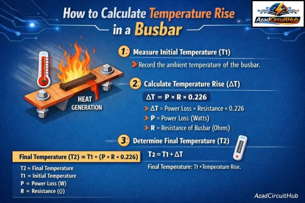
Table of Contents
Table of Contents
Quick Busbar Temperature Rise Calculation Guide
| Parameter | Typical consideration |
|---|---|
| Busbar material | Copper or aluminum |
| Current | Continuous operating current |
| Ambient temperature | Often 25°C to 40°C |
| Busbar resistance | Depends on material and dimensions |
| Heat generation | I²R losses |
| Heat dissipation | Convection + radiation |
| Surface area | Larger area improves cooling |
| Temperature rise | Busbar temperature − ambient temperature |
| Main concern | Maximum permissible conductor temperature |
The simplest definition is:
Temperature Rise = Busbar Temperature − Ambient Temperature
For example, if a busbar reaches 85°C in a 35°C ambient environment:
Temperature Rise = 85 − 35 = 50°C
This value is different from the actual busbar temperature. A 50°C temperature rise at a 35°C ambient temperature means the conductor operates at 85°C.
What Causes Busbar Temperature Rise?
The main source of heat in a busbar is resistive loss. When current passes through the conductor, electrical resistance converts some of the electrical energy into heat.
The fundamental equation is:
P = I²R
Where:
- P = heat generated in watts
- I = current in amperes
- R = busbar resistance in ohms
This equation shows why high-current applications require careful thermal design. If current doubles while resistance remains constant, heat generation increases by four times.
For example, a busbar carrying 500 A with a resistance of 0.0002 Ω produces:
P = 500² × 0.0002 = 50 W
Those 50 W must be transferred from the busbar to the surrounding environment.
How to Calculate Temperature Rise in a Busbar
A practical calculation starts by determining the busbar’s electrical losses and then estimating how effectively those losses can be dissipated.
Step 1: Determine Busbar Resistance
For a straight conductor, resistance can be estimated using:
R = ρL/A
Where:
- R = resistance in ohms
- ρ = electrical resistivity of the material
- L = conductor length in meters
- A = cross-sectional area in square meters
Copper has lower resistivity than aluminum, so a copper busbar of the same dimensions generally produces lower I²R losses.
Approximate resistivity values at 20°C are:
| Material | Resistivity at 20°C |
|---|---|
| Copper | 1.72 × 10⁻⁸ Ω·m |
| Aluminum | 2.82 × 10⁻⁸ Ω·m |
Actual resistance increases as conductor temperature increases. Therefore, using only the resistance at 20°C can underestimate operating losses.
Step 2: Calculate Heat Loss
Once resistance is known, calculate heat generation using:
P = I²R
Consider a copper busbar carrying 800 A with a resistance of 0.00015 Ω:
P = 800² × 0.00015
P = 96 W
The busbar must dissipate approximately 96 W under these conditions.
Step 3: Determine the Ambient Temperature
Ambient temperature has a direct effect on the final conductor temperature.
If the calculated temperature rise is 45°C and the surrounding air is 40°C:
Busbar Temperature = 40 + 45 = 85°C
Therefore, the same busbar operating at a 25°C ambient temperature would reach approximately 70°C under otherwise similar conditions.
Step 4: Estimate Thermal Dissipation
The heat generated by the busbar leaves through several mechanisms:
- Natural convection
- Forced-air convection
- Thermal radiation
- Heat conduction through supports and connections
The exposed surface area is especially important. A busbar with greater surface area can transfer more heat to the surrounding environment.
This is why busbar shape and orientation matter in addition to cross-sectional area.
Busbar Size and Temperature Rise
Busbar dimensions have a major effect on both electrical and thermal performance. Increasing the cross-sectional area reduces resistance, which lowers I²R losses. However, simply making a busbar thicker does not always provide the same thermal benefit as increasing its exposed surface area.
| Busbar size | Cross-sectional area | General thermal effect |
|---|---|---|
| 25 × 3 mm | 75 mm² | Higher resistance and heating |
| 25 × 5 mm | 125 mm² | Lower resistance |
| 40 × 5 mm | 200 mm² | Better current capacity |
| 50 × 5 mm | 250 mm² | Lower current density |
| 60 × 10 mm | 600 mm² | Suitable for high-current applications |
The actual allowable current cannot be determined from area alone. Enclosure size, ventilation, spacing between phases, mounting arrangement, ambient temperature, and applicable standards must also be considered.
For a broader conductor sizing check, you can use a Bus Bar Heat Capacity Calculator to compare current loading and thermal capacity before selecting a practical busbar size.
Effect of Busbar Material
Copper and aluminum are the two most common busbar materials.
Copper provides excellent electrical conductivity and generally requires less cross-sectional area for the same current. Aluminum has lower density and is often selected when weight and material cost are important.
| Property | Copper | Aluminum |
|---|---|---|
| Electrical conductivity | Higher | Lower |
| Density | Higher | Lower |
| Resistivity | Lower | Higher |
| Weight | Higher | Lower |
| Thermal conductivity | Excellent | Good |
| Typical application | Switchgear, panels, high-current systems | Distribution and large conductors |
When you Calculate Temperature Rise in a Busbar, always use material-specific electrical and thermal properties rather than applying the same assumptions to copper and aluminum.
Effect of Ambient Temperature
Ambient temperature is one of the most important factors in thermal design.
Suppose a busbar has a calculated temperature rise of 40°C.
| Ambient temperature | Temperature rise | Estimated busbar temperature |
|---|---|---|
| 20°C | 40°C | 60°C |
| 25°C | 40°C | 65°C |
| 30°C | 40°C | 70°C |
| 35°C | 40°C | 75°C |
| 40°C | 40°C | 80°C |
| 45°C | 40°C | 85°C |
The same electrical load can therefore produce different conductor temperatures in different environments.
This is particularly important for outdoor switchboards, rooftop electrical equipment, industrial plants, and poorly ventilated enclosures.
Busbar Temperature Rise Calculation Example
Consider a copper busbar with these characteristics:
| Parameter | Value |
|---|---|
| Material | Copper |
| Length | 2 m |
| Cross-sectional area | 500 mm² |
| Current | 600 A |
| Resistance | 0.00007 Ω |
| Ambient temperature | 35°C |
| Estimated heat loss | 25.2 W |
First calculate the heat generated:
P = I²R
P = 600² × 0.00007
P = 25.2 W
The next stage is estimating the temperature rise from the available heat-dissipation area. This normally requires a thermal model, manufacturer data, testing, or an applicable standard rather than a single universal formula.
If the thermal design establishes a 35°C rise:
Final busbar temperature = 35 + 35 = 70°C
This illustrates why busbar temperature rise calculation involves both electrical losses and thermal conditions.
A Useful Thermal Approximation
For preliminary engineering work, temperature rise can be represented conceptually as:
ΔT = P × Rθ
Where:
- ΔT = temperature rise in °C
- P = heat generated in watts
- Rθ = thermal resistance in °C/W
For example, if losses are 25.2 W and the effective thermal resistance is 1.4°C/W:
ΔT = 25.2 × 1.4 = 35.28°C
At a 35°C ambient temperature:
Busbar temperature ≈ 70.3°C
This approach is useful for understanding the relationship between electrical losses and thermal performance, but the actual thermal resistance must represent the installation conditions.
Factors That Increase Busbar Temperature
Several conditions can increase conductor temperature even when the nominal current remains unchanged.
| Factor | Effect on temperature |
|---|---|
| Higher current | Strong increase due to I²R losses |
| Higher ambient temperature | Raises final conductor temperature |
| Small cross-section | Increases resistance |
| Poor ventilation | Reduces heat removal |
| Tight phase spacing | Can reduce cooling |
| Dirty surfaces | May restrict heat transfer |
| Loose joints | Creates localized heating |
| High contact resistance | Produces additional I²R losses |
| Enclosed installation | Can increase internal temperature |
Loose connections deserve special attention. A poorly tightened joint can develop higher contact resistance and generate concentrated heat. In severe cases, this can lead to insulation damage, oxidation, or joint failure.
How Busbar Shape Affects Temperature Rise
Busbar shape influences its cooling performance. Flat rectangular busbars are common because they provide a large exposed surface relative to their cross-sectional area.
For the same cross-sectional area, orientation can also affect natural convection.
A busbar installed inside a compact enclosure may operate hotter than an identical conductor mounted in open air. Therefore, laboratory current ratings should not automatically be applied to every real-world installation.
If your design involves comparing flat, tubular, or rectangular conductors, a Bus Bar Heat Capacity Calculator can help provide an initial comparison before detailed thermal verification.
Standards and Temperature Limits
Busbar temperature limits should be checked against the standard governing the equipment. Depending on the application, relevant requirements may come from IEC or NEC-related equipment standards, manufacturer specifications, and switchgear testing requirements.
Do not assume that one universal maximum temperature applies to every busbar. The allowable temperature can depend on:
- Busbar material
- Insulation system
- Joint construction
- Equipment enclosure
- Nearby components
- Terminal ratings
- Applicable standard
- Manufacturer’s tested assembly
For production switchgear, a tested and certified assembly should take priority over a simplified theoretical calculation.
Practical Ways to Reduce Busbar Temperature
If your calculated temperature is too high, several design changes can help.
- Increase busbar cross-sectional area.
- Use a material with better electrical conductivity.
- Increase exposed surface area.
- Improve enclosure ventilation.
- Increase spacing between current-carrying conductors where permitted.
- Reduce unnecessary connection resistance.
- Use forced-air cooling for suitable high-power systems.
- Check joints for proper torque and contact quality.
- Reduce continuous loading where practical.
- Verify the design using the applicable standard or manufacturer’s test data.
For high-current systems, checking thermal performance before fabrication is much easier than correcting overheating after commissioning. A Bus Bar Heat Capacity Calculator can also be useful as an initial screening tool when comparing different busbar configurations.
Common Mistakes in Busbar Temperature Calculations
A common mistake is treating ampacity as a fixed value regardless of installation conditions. In reality, current-carrying capacity is influenced by temperature, ventilation, enclosure construction, conductor arrangement, and permissible operating temperature.
Another mistake is ignoring resistance changes with temperature. Copper and aluminum both become more resistive as temperature rises. This means heat generation can increase as the conductor gets hotter.
It is also important to distinguish between temperature rise and absolute temperature.
For example:
40°C temperature rise + 40°C ambient = 80°C busbar temperature
It would be incorrect to report 40°C as the conductor’s operating temperature.
FAQs About Busbar Temperature Rise
1. What is busbar temperature rise?
Busbar temperature rise is the difference between the busbar’s operating temperature and the surrounding ambient temperature. It is primarily caused by resistive heating from current flow and is affected by the conductor’s ability to dissipate heat.
2. How do you calculate busbar temperature rise?
To Calculate Temperature Rise in a Busbar, first determine its electrical losses using P = I²R. Then evaluate how effectively those losses are dissipated through convection, radiation, and conduction. A thermal resistance approach can be used for preliminary calculations.
3. Why does busbar temperature increase with current?
Busbar heating follows the I²R relationship. Because current is squared in the equation, a relatively small increase in current can cause a much larger increase in heat generation.
4. Does a larger busbar reduce temperature rise?
Generally, increasing the cross-sectional area reduces electrical resistance and therefore reduces I²R losses. However, the final temperature also depends on surface area, enclosure conditions, airflow, ambient temperature, and busbar arrangement.
5. What is an acceptable busbar temperature rise?
There is no single value that applies to every busbar installation. The acceptable temperature depends on the equipment design, insulation, connections, surrounding components, ambient conditions, and applicable IEC, NEC-related, or manufacturer requirements. Always verify the final design against the relevant standard.
Get new guides in your feed. Follow Electrical Insights on LinkedIn for new electrical standards guides, calculators and design tips from Azad Circuit Hub.
#BusbarTemperatureRise, #BusbarSizing, #BusbarAmpacity, #ElectricalEngineering, #BusbarDesign, #ElectricalCalculations, #CopperBusbar, #AluminumBusbar, #IECStandards, #PowerDistribution