Maximum Operating Temperature for Busbars: Copper and Aluminum
The Maximum Operating Temperature Busbars depends on the conductor material, insulation system, terminal ratings, enclosure design, and applicable electrical standard. Copper and aluminum can withstand high temperatures, but the allowable temperature of an installed busbar is often limited by its weakest component.
| Parameter | Copper Busbar | Aluminum Busbar |
|---|---|---|
| Typical continuous design range | 60–90°C | 60–90°C |
| Common insulated equipment limit | Often 75°C or 90°C, depending on design | Often 75°C or 90°C, depending on design |
| Melting point | Approximately 1,085°C | Approximately 660°C |
| Electrical conductivity | Higher | Lower |
| Thermal expansion | Lower | Higher |
| Main temperature concern | Joint heating and oxidation | Joint heating, oxide formation, and expansion |
Important: These operating ranges are not universal limits. The permissible temperature must come from the applicable equipment standard, manufacturer documentation, and the temperature rating of connected components.
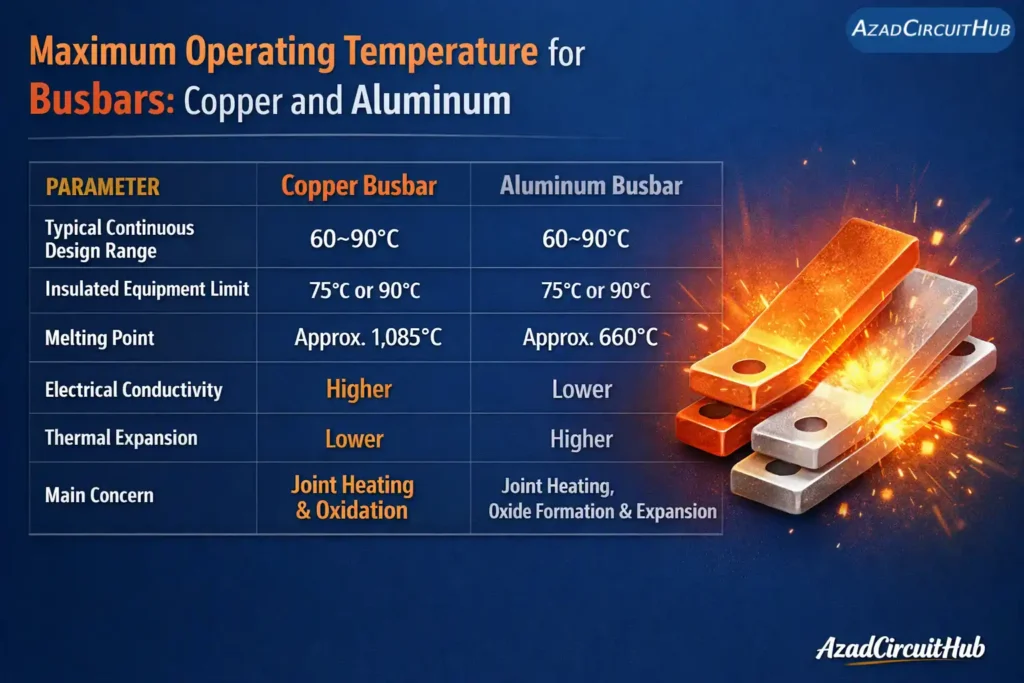
Table of Contents
Table of Contents
Maximum Operating Temperature for Busbars: Copper and Aluminum
The Maximum Operating Temperature for Busbars is not determined by melting point alone. Busbars must carry rated current without excessive temperature rise, loss of mechanical strength, or damage to nearby insulation and electrical connections.
In low-voltage switchgear, temperature limits depend on the applicable product standard and the specific component being evaluated. A bare copper busbar may tolerate a higher temperature than an insulated connection or a terminal connected to a circuit breaker.
| Busbar or Component | Temperature Consideration |
|---|---|
| Bare copper busbar | Limited by design, oxidation, joint performance, and surrounding materials |
| Bare aluminum busbar | Limited by joint stability, oxide formation, mechanical properties, and design |
| Insulated busbar | Limited by insulation temperature rating and equipment design |
| Circuit-breaker terminal | Must remain within the manufacturer’s permitted temperature |
| Bolted busbar joint | Requires controlled contact resistance and acceptable temperature rise |
| Switchgear assembly | Must satisfy the applicable assembly verification requirements |
For practical installations, always distinguish between the conductor’s maximum material temperature, its operating temperature, and the measured temperature rise above ambient.
What NEC and IEC Standards Say About Busbar Temperature
Two important standards frameworks apply to busbar temperature in electrical installations and equipment.
| Standard | Relevant Reference | Application |
|---|---|---|
| NFPA 70, National Electrical Code (NEC) | 110.14(C) | Temperature limitations for electrical connections and equipment terminations |
| NFPA 70, NEC | 110.3(B) | Installation and use according to equipment listing, labeling, and instructions |
| IEC 61439-1 | Clause 10.10 | Temperature-rise verification of low-voltage switchgear and controlgear assemblies |
| IEC 61439-1 | Clause 8.2.1 | Resistance to heat and fire, including requirements relevant to insulating materials |
| IEC 60947-1 | Temperature-rise provisions | General requirements for low-voltage switchgear and controlgear equipment |
NEC 110.14(C) is particularly important when busbars connect to circuit breakers, disconnects, or other terminals. The applicable termination temperature rating and equipment instructions must be considered when selecting conductors and assessing connections.
IEC 61439-1 Clause 10.10 addresses temperature-rise verification for low-voltage assemblies. The permitted temperature depends on the relevant component, material, and verification criteria. It is not correct to apply one universal temperature limit to every copper or aluminum busbar.
Use the edition adopted by the relevant jurisdiction and verify clause numbering against that edition before final design approval.
Maximum Temperature of Copper Busbars
Copper has high electrical conductivity and good thermal conductivity, making it widely used in distribution boards, switchgear, transformer connections, and industrial control panels.
The maximum permissible temperature of a copper busbar depends on its cross-sectional area, current density, surface finish, ventilation, ambient temperature, and joint construction. A busbar operating at 90°C is not automatically acceptable simply because copper melts at approximately 1,085°C.
The insulation, terminal materials, and equipment verification limits may impose a much lower operating ceiling.
For example, a copper busbar carrying heavy current inside a poorly ventilated enclosure may experience a greater temperature rise than the same busbar in a ventilated assembly.
Before increasing the rated current, perform a copper busbar temperature rise calculation to assess conductor heating and verify the result against the equipment design and applicable standard.
Maximum Temperature of Aluminum Busbars
Aluminum is lighter and often less expensive than copper, making it suitable for many power distribution systems. However, aluminum has lower electrical conductivity, so a larger cross-sectional area is often needed to achieve comparable resistance.
Aluminum melts at approximately 660°C, but this is not a practical operating limit. Its mechanical properties, joint integrity, thermal expansion, and oxidation behavior must be considered well before that temperature.
Aluminum busbar connections require suitable surface preparation, compatible terminals, and manufacturer-approved jointing practices. Oxide films can increase contact resistance if joints are not designed and assembled correctly.
| Property | Copper | Aluminum |
|---|---|---|
| Approximate melting point | 1,085°C | 660°C |
| Relative conductivity by volume | Higher | Lower |
| Weight for equal volume | Higher | Lower |
| Thermal expansion | Lower | Higher |
| Joint considerations | Contact pressure and surface condition | Oxide control, compatible hardware, and expansion |
The correct choice depends on total installation cost, available space, rated current, mechanical requirements, and maintenance conditions.
How to Calculate Busbar Temperature Rise
Temperature rise is the difference between the measured busbar temperature and the surrounding ambient temperature.
Formula:
Temperature Rise (°C) = Busbar Temperature (°C) − Ambient Temperature (°C)
Example:
- Ambient temperature = 35°C
- Measured busbar temperature = 80°C
- Temperature rise = 80 − 35 = 45°C
The result is a 45°C temperature rise. Whether this is acceptable depends on the applicable assembly standard, component limits, and manufacturer’s specifications.
For preliminary thermal assessment, conductor losses can be estimated using:
P = I² × R
Where:
- P = power loss in watts (W)
- I = current in amperes (A)
- R = conductor resistance in ohms (Ω)
Resistance increases as conductor temperature rises. Joint resistance can also create localized hot spots, so a simple conductor-loss calculation does not replace temperature-rise verification.
For quick preliminary estimates, use the Bus Bar Heat Capacity Calculator and confirm the final design through the relevant engineering checks.
What Is the Best Material for a Busbar?
Copper is often preferred where space is limited, conductivity is important, or compact connections are required. Aluminum can be a better option for large distribution systems where reduced weight and material cost are important.
The best material is the one that meets the required current rating, temperature-rise limit, mechanical strength, fault withstand capability, and installation budget.
Neither material should be selected using melting point alone. The complete assembly and its connections determine whether the installation can operate safely.
Expert Field Note: Preventing Busbar Overheating
In practical switchgear work, I pay close attention to bolted joints, contact surfaces, and ventilation before blaming the busbar itself. Thermal imaging under a representative load can reveal uneven heating, but readings must be interpreted with emissivity, load balance, and manufacturer limits in mind.
Frequently Asked Questions
1. Why are busbars not insulated?
Busbars are often left uninsulated inside electrical panels because air provides cooling, and bare conductors are easier to inspect and connect. However, they must have adequate electrical clearances, barriers, and enclosure protection to prevent accidental contact and short circuits. IEC 61439-1 Clause 8.4 addresses protection against electric shock in low-voltage assemblies.
2. What is the maximum operating temperature for copper?
Copper busbars do not have one universal maximum operating temperature. The allowable temperature depends on the assembly design, insulation, connected terminals, and manufacturer specifications. Copper melts at approximately 1,085°C, but this is not a safe operating limit. NEC 110.14(C) addresses conductor termination temperature limitations, while IEC 61439-1 Clause 10.10 covers temperature-rise verification of low-voltage assemblies.
3. What is the maximum operating temperature that aluminum can withstand?
Aluminum melts at approximately 660°C, but its practical operating temperature must remain well below this point. The permitted temperature depends on joint integrity, mechanical properties, insulation, and equipment ratings. Aluminum busbars require particular attention to oxide formation and thermal expansion. IEC 61439-1 Clause 10.10 provides the relevant framework for verifying assembly temperature rise.
4. What is the best material for a busbar?
Copper is generally preferred for compact installations because it offers higher electrical conductivity and allows smaller conductor dimensions. Aluminum is often preferred for large power distribution systems because it is lighter and can reduce material costs. The best choice depends on current capacity, temperature rise, mechanical strength, short-circuit withstand, installation space, and budget.
5. What is the lifespan of a busbar?
A properly designed, installed, and maintained busbar can serve for several decades, depending on operating conditions and equipment quality. Excessive heating, corrosion, loose joints, repeated thermal cycling, and insulation deterioration can shorten its lifespan. Regular inspections, thermal imaging under representative loads, and checks of electrical connections help identify problems before failure occurs.
6. Which insulators are used for bus bars?
Common busbar insulation and support materials include epoxy resin, glass-reinforced polyester (GRP), porcelain or other suitable ceramics, and electrical-grade thermoplastics. The choice depends on operating voltage, temperature, mechanical loading, moisture, and tracking resistance. IEC 61439-1 Clause 8.2.1 addresses resistance to heat and fire for relevant insulating materials; the selected material must also satisfy the assembly’s dielectric and mechanical requirements.
Final Recommendations
The maximum operating temperature of busbars must be established from the actual assembly design, not simply from the melting point of the metal. Check the manufacturer’s temperature limits, terminal ratings, insulation class, ambient conditions, and applicable NEC or IEC requirements.
For reliable operation, use correctly rated busbars, maintain sound electrical joints, provide suitable ventilation, and investigate abnormal temperature differences under load. These practices help reduce overheating risks and improve the long-term reliability of switchgear and power distribution systems.
Get new guides in your feed. Follow Electrical Insights on LinkedIn for new electrical standards guides, calculators and design tips from Azad Circuit Hub.