
Earthing Cable Size Standard | IEC vs NEC vs BS 7671 vs IEEE 80 | Calculation
Selecting the correct grounding conductor is one of the most important decisions in electrical design. A properly sized earthing conductor safely carries fault current, minimizes touch voltage risks, protects equipment, and helps electrical systems comply with national regulations.
However, there is no single global rule that applies everywhere. Different countries and industries follow different design codes, each using its own sizing methodology and application requirements. Understanding these differences helps engineers, consultants, contractors, and inspectors avoid design errors while ensuring compliance.
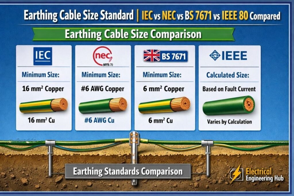
Table of Contents
Table of Contents
This guide compares the major Earthing Cable Size Standards used worldwide, explains where each standard applies, and highlights the key differences between their sizing methods.
Why Earthing Cable Size Requirements Differ by Standard
There is no universal earthing cable size because electrical regulations have evolved independently across different regions. Every standard reflects local safety practices, electrical infrastructure, installation methods, and regulatory requirements.
For example, commercial buildings in Europe commonly follow IEC standards, while electrical installations in the United States must comply with the National Electrical Code (NEC). The United Kingdom applies BS 7671, which is based largely on IEC principles but includes national requirements. Utility substations often use IEEE 80 because their grounding systems face much higher fault currents and unique touch-voltage considerations.
Engineers working on international projects frequently encounter multiple standards within a single facility. Imported equipment may follow IEC requirements while the building installation must comply with NEC or BS 7671.
When comparing Earthing Cable Size Standards, always consider:
| Design Factor | Why It Matters |
|---|---|
| Project location | Determines the legally applicable code |
| Installation type | Residential, commercial, industrial, or utility |
| Fault current level | Influences conductor thermal capacity |
| Protection device clearing time | Affects allowable conductor heating |
| Regulatory authority | Local inspectors enforce specific standards |
Understanding which standard governs your project is always the first step before calculating conductor size.
IEC 60364-5-54 (International)
IEC 60364-5-54 is one of the most widely adopted international standards for protective earthing systems. It is used directly or adapted by many countries throughout Europe, Asia, the Middle East, and Africa.
Unlike table-based approaches, IEC primarily sizes protective conductors using the adiabatic equation. This method considers the thermal energy generated during a fault and determines the minimum conductor cross-sectional area capable of withstanding that energy without damage.
For detailed Calculation explore our guide on Earthing Cable Size as Per IEC 60364-5-54
The simplified equation is based on:
- Prospective fault current
- Fault clearing time
- Conductor material
- Initial and final conductor temperatures
Where the protective conductor is installed under specific conditions, IEC also specifies minimum cross-sectional areas that may be used without performing a complete adiabatic calculation.
Common minimum values include:
| Protective Conductor Condition | Typical Minimum Size |
|---|---|
| Copper with mechanical protection | 2.5 mm² |
| Copper without mechanical protection | 4 mm² |
The standard also includes guidance for bonding conductors, earth electrodes, PEN conductors, and equipotential bonding.
Since the complete calculation process involves several variables, it is usually more practical to use a dedicated IEC earthing cable size calculator rather than performing manual calculations for every installation.
NEC 250.66 (United States)
The National Electrical Code (NFPA 70) takes a significantly different approach compared to IEC.
Instead of calculating conductor size from fault current and clearing time, NEC Article 250.66 provides a sizing table for the grounding electrode conductor. The required conductor size depends primarily on the size of the service entrance conductors.
This makes NEC easier to apply during building design because engineers simply identify the service conductor size and select the corresponding grounding conductor from the table.
Typical examples include:
| Largest Service Conductor | Minimum Copper Grounding Electrode Conductor |
|---|---|
| 2 AWG or smaller | 8 AWG |
| 1/0 to 3/0 AWG | 4 AWG |
| 350 to 600 kcmil | 1/0 AWG |
| Over 1100 kcmil | 3/0 AWG |
NEC also contains separate requirements for:
- Equipment grounding conductors
- Bonding jumpers
- Grounding electrode systems
- Separately derived systems
- Grounding for services and feeders
It is important to understand that NEC distinguishes between grounding electrode conductors and equipment grounding conductors. These conductors perform different functions and are sized using different NEC tables.
For building installations throughout the United States, NEC compliance is mandatory unless modified by the local authority having jurisdiction (AHJ).
NEC Grounding Table 250.122 for Earthing Conductor Sizing
The NEC Grounding Table 250.122 provides a practical method for selecting the minimum size of an equipment grounding conductor (EGC) based on the rating of the overcurrent protective device. It is an important reference when comparing an Earthing Cable Size Standard under NEC requirements with IEC, BS 7671, or IEEE 80 practices.
| Overcurrent Device | Minimum Copper EGC |
|---|---|
| 15 A | 14 AWG |
| 20 A | 12 AWG |
| 30 A | 10 AWG |
| 40–60 A | 10 AWG |
| 100 A | 8 AWG |
| 200 A | 6 AWG |
| 400 A | 3 AWG |
| 600 A | 1 AWG |
For a complete explanation of conductor sizing, adjustment requirements, and examples, see this detailed guide to the NEC Grounding Table 250.122.
Grounding Cable Size as Per NEC
Under the NEC, grounding conductor sizing is primarily based on the overcurrent protective device (OCPD) protecting the circuit. NEC Table 250.122 provides the minimum size for an equipment grounding conductor (EGC).
| OCPD Rating | Minimum Copper EGC | Minimum Aluminum EGC |
|---|---|---|
| 15 A | 14 AWG | 12 AWG |
| 20 A | 12 AWG | 10 AWG |
| 30 A | 10 AWG | 8 AWG |
| 60 A | 10 AWG | 8 AWG |
| 100 A | 8 AWG | 6 AWG |
| 200 A | 6 AWG | 4 AWG |
| 400 A | 3 AWG | 1 AWG |
For circuits where the ungrounded conductors are increased in size, NEC 250.122(B) may require a proportional increase in the EGC.
This makes the NEC approach different from IEC-based calculations, where fault current and disconnection requirements are commonly considered. For a detailed comparison, see this Grounding Cable Size as Per NEC guide within our broader Earthing Cable Size Standard reference.
BS 7671 (United Kingdom)
BS 7671, commonly known as the IET Wiring Regulations, governs electrical installations throughout the United Kingdom.
Although BS 7671 closely follows IEC 60364, it provides UK-specific guidance, practical recommendations, and installation requirements suited to British electrical practices.
Like IEC, BS 7671 permits sizing protective conductors using the adiabatic equation when fault current and disconnection time are known.
Use our online tool for earth cable sizes uk
The calculation considers:
- Fault current
- Protective device operating time
- Conductor material
- Thermal characteristics
Where calculations are unnecessary or impractical, BS 7671 also specifies minimum conductor sizes depending on installation conditions and mechanical protection.
Common practical values include:
| Conductor Type | Typical Minimum Copper Size |
|---|---|
| Protected CPC | 2.5 mm² |
| Unprotected CPC | 4 mm² |
| Main protective bonding | As specified by BS 7671 tables |
Electrical designers in the UK frequently use sizing tables alongside the adiabatic method depending on the installation.
For projects within the UK, using a dedicated BS 7671 earthing cable size calculator can simplify compliance while ensuring the selected conductor satisfies the current edition of the Wiring Regulations.
IEEE 80 (Substation Grounding)
IEEE 80 serves a very different purpose from the previous standards.
Rather than focusing on building wiring, IEEE 80 is specifically developed for high-voltage substations and utility grounding systems.
Its objective extends beyond conductor thermal capacity. The standard aims to protect personnel from dangerous step voltage and touch voltage while maintaining acceptable ground potential rise during major fault events.
Find more about iec grounding standards
IEEE 80 considers numerous design variables including:
- Soil resistivity
- Fault current magnitude
- Grid geometry
- Burial depth
- Surface material
- Ground rod arrangement
- Grid resistance
- Fault duration
Because substations may experience extremely high fault currents, grounding design becomes much more complex than selecting a conductor from a sizing table.
The standard evaluates the complete grounding grid rather than only the conductor cross-sectional area.
Key design objectives include:
| Design Parameter | Purpose |
|---|---|
| Step voltage | Personnel safety while walking |
| Touch voltage | Safe equipment contact |
| Grid resistance | Effective fault current dissipation |
| Ground potential rise | System stability during faults |
IEEE 80 should therefore be viewed as a specialized grounding design standard rather than a direct alternative to IEC, NEC, or BS 7671 for ordinary building installations.
Find all about substation earthing design
Side-by-Side Comparison Table
The following comparison provides a quick overview of the major Earthing Cable Size Standards.
| Standard | Region / Scope | Primary Method | Typical Minimum Size | Key Reference |
|---|---|---|---|---|
| IEC 60364-5-54 | International | Adiabatic equation | 2.5 mm² or 4 mm² depending on protection | IEC 60364-5-54 |
| NEC 250.66 | United States | Service conductor sizing table | Based on service conductor size | NEC Article 250.66 |
| BS 7671 | United Kingdom | Adiabatic equation with UK guidance | 2.5 mm² or 4 mm² in common installations | BS 7671 |
| IEEE 80 | Utility substations | Ground grid analysis, step and touch voltage | Project specific | IEEE Std 80 |
This comparison illustrates that each standard addresses different installation environments and therefore uses different sizing philosophies.
Here’s a compact, SEO-friendly section designed to fit naturally into your existing standards article:
Earth Cable Size Calculator for Earthing Systems
An Earth Cable Size Calculator helps electricians and engineers estimate the protective conductor size based on fault current, disconnection time, conductor material, and installation conditions. It provides a practical starting point, but the final selection should always be checked against the applicable Earthing Cable Size Standard, such as IEC 60364, NEC, BS 7671, or IEEE 80.
| Input | Typical consideration |
|---|---|
| Fault current | Prospective earth-fault current |
| Disconnection time | Protective-device operating time |
| Conductor | Copper or aluminum |
| Installation | Buried, conduit, tray, etc. |
For detailed calculations, including standard-specific requirements and conductor sizing methods, use our Earth Cable Size Calculator to verify the recommended earthing conductor size before installation.
Size of Earth Wire for Domestic Wiring in SWG
For domestic electrical installations, the earth wire size depends on the circuit, protective device, conductor size, and applicable code. SWG is an older wire-gauge system, so modern installations should primarily follow the relevant standard rather than selecting a wire by SWG alone.
| Domestic circuit | Typical copper earth wire | Approx. SWG* |
|---|---|---|
| Lighting circuits | 1.5 mm² | 16 SWG |
| Socket circuits | 2.5 mm² | 14 SWG |
| Higher-load circuits | 4 mm² | 12 SWG |
| Main earthing conductor | 6 mm²+ | 10 SWG+ |
*Approximate conversion; verify the required cross-sectional area against local regulations.
For a detailed comparison of conductor sizing, protection, and international requirements, see our guide to the Size of Earth Wire for Domestic Wiring in SWG and use it alongside the applicable Earthing Cable Size Standard.
Which Standard Should You Use?
The correct standard depends entirely on your project requirements rather than personal preference.
Use IEC 60364-5-54 when:
- Designing installations in countries adopting IEC standards
- Working on industrial facilities throughout Europe, Asia, Africa, or the Middle East
- Equipment specifications reference IEC requirements
Use NEC 250.66 when:
- Designing electrical installations within the United States
- Local authorities enforce NFPA 70
- Building permits require NEC compliance
Get instant results with our online tool earth cable size calculator
Use BS 7671 when:
- Working on electrical installations in the United Kingdom
- Following IET Wiring Regulations
- Designing residential, commercial, or industrial UK projects
Use IEEE 80 when:
- Designing substations
- Developing transmission or distribution grounding grids
- Evaluating step and touch voltage safety
Some international projects require compliance with more than one standard. For example, a manufacturing facility in the United States may follow NEC for the building installation while imported machinery is designed according to IEC requirements. In these cases, engineers must ensure that both regulatory obligations and equipment specifications are satisfied without compromising safety.
Size of Earthing Conductors by Application
The required conductor size depends on the fault current, protective-device rating, installation method, and applicable code. The following practical guide complements the broader Earthing Cable Size Standard comparison of IEC, NEC, BS 7671, and IEEE 80 requirements.
| Application | Typical Earthing Conductor | Common Size Range* | Main Consideration |
|---|---|---|---|
| Residential final circuits | Copper CPC/PE | 1.5–6 mm² | Circuit conductor and protection |
| Lighting circuits | Copper PE | 1.5–2.5 mm² | Fault-clearing requirements |
| Socket circuits | Copper PE | 2.5–6 mm² | Breaker and cable size |
| Distribution feeders | Copper/Aluminum PE | 6–35+ mm² | Fault current and installation |
| Transformer neutral earthing | Copper/Aluminum | 16–120+ mm² | Transformer fault level |
| Motor equipment | Copper PE | 2.5–35+ mm² | Motor circuit protection |
| Solar PV systems | Copper PE | 4–35+ mm² | PV fault current and bonding |
| Main earthing conductor | Copper/Aluminum | 16–70+ mm² | Supply and earthing arrangement |
For larger installations, conductor sizing should be verified using the applicable thermal or adiabatic fault-current calculation.
Earthing Cable Size for Solar Plants
Choosing the right earthing cable size for solar plants is essential for safely carrying fault current and protecting PV modules, structures, inverters, and other equipment. The required conductor size depends on fault current, disconnection time, installation method, material, and the applicable Earthing Cable Size Standard.
| Solar Plant Component | Typical Earthing Conductor |
|---|---|
| PV module frames | 4–6 mm² Cu |
| Mounting structure | 6–16 mm² Cu |
| Inverter equipment | 16–35 mm² Cu |
| Main grounding grid | 35–70 mm² Cu |
For large solar farms, final sizing should be verified using fault-current and thermal calculations rather than relying only on typical values. The number and location of earth connections also depend on the plant design and grounding system. For a practical guide, see how many earthing required for solar system to understand grounding points and earthing arrangements for PV installations.
Earth Cable Size for Lightning Protection
Lightning protection systems need a properly sized earthing conductor to safely discharge high surge currents into the ground. The required size depends on the lightning protection design, conductor material, installation method, and applicable standard. As a practical reference, copper conductors of 16–50 mm² are commonly considered for lightning earthing applications, but the final selection should follow the project standard and risk assessment.
| Application | Typical Copper Conductor |
|---|---|
| Lightning bonding | 16 mm² |
| Lightning down conductor earthing | 25–35 mm² |
| Main lightning earth connection | 35–50 mm² |
When applying the Earthing Cable Size Standard, avoid selecting a conductor based only on fault-current sizing. For a detailed selection guide, see our lightning arrester earthing cable size article, which covers practical sizing considerations and installation requirements.
Earth Cable Size for Bonding
The correct Earth Cable Size for Bonding depends on the fault current, protective device, conductor size, installation method, and applicable electrical standard. Bonding conductors provide a low-impedance path for fault current and help maintain equipotential bonding between exposed conductive parts.
| Application | Typical Bonding Conductor Approach |
|---|---|
| Equipment bonding | Sized according to applicable code |
| Main bonding | Based on supply/protective conductor requirements |
| Protective bonding | Selected for fault-current withstand |
| Industrial installations | Verify with fault-current and thermal calculations |
When selecting an Earth Cable Size for Bonding, always verify the installation against the applicable Earthing Cable Size Standard, such as IEC 60364, NEC, BS 7671, or IEEE guidance. For detailed conductor selection methods, fault-current calculations, and practical sizing examples, see our complete guide on Earth Cable Size for Bonding.
Formula for Earth Conductor Size Calculation
The most widely used formula for sizing earth conductors comes from IEC 60364-5-54. The formula is:
S = (I × √t) / (k)
Where:
- S = Minimum cross-sectional area of the conductor (mm²)
- I = Fault current (A)
- t = Fault duration (seconds)
- k = Constant depending on conductor material and insulation type
The constant k takes into account the conductor’s material (copper or aluminum), its initial temperature, final permissible temperature, and resistivity. For example, copper with PVC insulation has k ≈ 115, while aluminum with PVC insulation has k ≈ 76.
This equation guarantees that the conductor does not exceed its permissible temperature rise during a fault.
Earth Conductor Size Calculation: Step by Step Worked Examples
Step 1: Determine Fault Current
The first step is calculating the maximum earth fault current that can flow during a short-circuit condition. This is typically obtained from system fault analysis. For example, if a 400V three-phase system has a prospective fault current of 10 kA, this value will be used for sizing.
Step 2: Identify Fault Duration
Protective devices like circuit breakers or fuses determine how long the fault current will last. Modern protection systems usually clear faults within 0.2 to 1 second. For conservative design, 1 second is often taken unless a faster device is confirmed.
Step 3: Select Conductor Material and k-Value
Choose between copper or aluminum, depending on cost and availability. Copper has higher conductivity and allows for smaller conductor sizes compared to aluminum. For copper with PVC insulation, the k value is 115.
Step 4: Apply the Formula
Let’s take an example:
- Fault current (I) = 10,000 A
- Fault duration (t) = 1 second
- Conductor material = Copper, k = 115
S = (10,000 × √1) / 115
S = 87 mm²
So, the minimum earth conductor cross-section should be 87 mm². In practice, the next standard size, 95 mm², is selected.
Step 5: Check with Minimum Standard Requirements
Standards also specify minimum conductor sizes regardless of calculation results. For example, IEC requires:
- 16 mm² for copper if unprotected
- 25 mm² for aluminum if unprotected
If conductors are mechanically protected, smaller sizes may be acceptable.
Step 6: Adjust for Practical Installation
Once the theoretical size is calculated, consider installation conditions. For example, long runs may require larger sizes to reduce resistance. Mechanical protection and redundancy also influence the final choice.
Table: k Values for Different Materials and Insulations
| Material | Insulation Type | k Value (A·√s/mm²) |
|---|---|---|
| Copper | PVC | 115 |
| Copper | XLPE | 143 |
| Aluminum | PVC | 76 |
| Aluminum | XLPE | 94 |
Example 2: Aluminum Conductor
Let’s calculate for aluminum conductor under the same fault conditions:
- Fault current = 10,000 A
- Fault duration = 1 second
- k = 76
S = (10,000 × √1) / 76
S = 131 mm²
The nearest standard aluminum conductor size is 150 mm².
Simplified Rules for Quick Sizing
While the formula is precise, in practice, electricians often follow simplified rules:
- If phase conductor ≤ 16 mm², earth conductor = same size as phase conductor.
- If phase conductor between 16 mm² and 35 mm², earth conductor = 16 mm².
- If phase conductor > 35 mm², earth conductor = half the phase conductor size.
These rules come from IEC 60364 and are widely used for small to medium installations.
Practical Design Example
Suppose we have a three-phase, 415V distribution board with:
- Prospective fault current = 6 kA
- Protection trip time = 0.5 s
- Material = Copper with PVC insulation
Calculation:
S = (6000 × √0.5) / 115
S = (6000 × 0.707) / 115
S = 36.8 mm²
The nearest standard size is 50 mm² copper conductor. This size ensures both safety and compliance.
Earth Resistance Testers
The formulas and tables above show that the earthing conductor can carry the fault current. They do not show how well the electrode connects to the soil. Only an earth resistance test does that, and many project specifications and inspection schedules require earth electrode resistance to be measured at commissioning and again at regular intervals.
A multimeter or an insulation tester cannot do this job. You need a dedicated earth ground tester. Soil moisture and temperature change the reading through the year, so record the date and ground conditions with every result. For the wider design picture, see our IEC earthing system guide.
As an electrical engineer with over 15 years of hands-on experience in electrical troubleshooting and renewable energy design, my advice is to treat the earth test as a commissioning record, not a formality. Measure before energizing, note the date and soil condition, and repeat the test at a fixed interval so you can see the trend. A reading that climbs from one season to the next often points to dry soil or a corroded connection before it becomes a protection problem.
The three testers below cover the most common situations. All three are intended for use by qualified persons.
| Tester | Method | Auxiliary stakes | Soil resistivity |
|---|---|---|---|
| Fluke 1625-2 Advanced GEO | 3- and 4-pole fall-of-potential, selective, stakeless | Optional, depends on method | Yes (4-pole) |
| Fluke 1630-2 FC clamp | Stakeless loop measurement | No | No |
| Kyoritsu KEW 4105A | Fall-of-potential | Yes, two | No |
Fluke 1625-2 Advanced GEO earth ground tester: best for soil resistivity and new grids
Best for substations, solar plants, new grounding grids, and anyone who wants one instrument for every test method.
- Performs 3- and 4-pole fall-of-potential tests, 4-pole soil resistivity tests, selective tests with one clamp, and stakeless tests with two clamps.
- Soil resistivity readings feed the design work described in our substation earthing design guide and the IEEE 80 section above.
- IP56 rated for outdoor use, with memory for up to 1,500 records and USB transfer for commissioning reports.
- Adjustable limits and color-coded leads make repeat testing faster.
Choose it if you design or commission earthing systems and need soil resistivity as well as electrode resistance.
Check price on AmazonFluke 1630-2 FC earth ground clamp: best for stakeless testing
Best for routine checks on existing earthing where you cannot drive stakes, such as paved yards, indoor installations, and rooftops.
- Measures the earth loop through a clamp jaw, so there are no auxiliary stakes to place.
- Reaches grounding components in hard-to-reach spaces, including indoors and fully paved areas.
- Calculates earth ground impedance at 55 Hz (R*), which better reflects what a fault would see.
- Limitation: it measures a loop, so it only works when the electrode is one of several parallel earth paths, as in a multi-grounded system. It cannot test a single isolated rod.
Choose it for maintenance rounds on multi-grounded sites, where it saves the time of laying out test stakes.
Check price on AmazonKyoritsu KEW 4105A digital earth resistance tester: best for rod earths on a budget
Best for electricians and contractors testing rod earths on domestic, commercial, and small industrial installations.
- A dedicated digital earth resistance tester that uses the classic fall-of-potential method with two auxiliary stakes.
- Sold with a hard carrying case for site use.
- Simpler and lower in cost than the Fluke kit, which suits routine electrode checks after installation.
- It measures electrode resistance only. It does not do soil resistivity or clamp-based testing.
Choose it if your work is mostly rod and plate earths and you want a straightforward tester at a lower cost.
Check price on AmazonWhich earth tester should you pick?
Need soil resistivity or a new grid to commission: the Fluke 1625-2.
Checking existing multi-grounded earthing without stakes: the Fluke 1630-2 FC.
Routine rod tests on a tighter budget: the Kyoritsu KEW 4105A.
Many engineers carry a stake-based tester and a clamp, because each covers the other’s gaps. For more test equipment, see our product reviews.
How do you test earth resistance?
The common method is fall-of-potential. The tester drives a current through the electrode under test and an auxiliary current stake, then measures the voltage against a second auxiliary stake. It calculates resistance from the two. Clamp testers measure the loop instead, need no stakes, and only work on multi-grounded systems.
What is an acceptable earth resistance value?
There is no single number. It depends on the applicable code, the system type, and the project specification. Substations and lightning protection systems generally need lower values than a small domestic installation, so check your specification. Our guide to earth cable size for lightning protection covers that application.
Can you measure earth resistance with a multimeter?
No. A multimeter does not run the alternating test current through auxiliary stakes that the fall-of-potential method needs, and stray ground voltages distort DC readings. Use a dedicated earth tester.
As an Amazon Associate I earn from qualifying purchases. See our Affiliate Disclosure. Prices and availability change, so check the Amazon listing before you buy.
Minimum Earthing Conductor Size
The minimum earthing conductor size depends on the installation standard, fault current, disconnection time, conductor material, and protective device. As part of an Earthing Cable Size Standard comparison, IEC 60364 commonly permits sizing the protective conductor from the phase conductor size, while NEC uses minimum copper/aluminum sizes based on the overcurrent protective device. BS 7671 follows a similar protective-conductor sizing approach.
| Phase Conductor Size | Typical IEC/BS 7671 PE Size* |
|---|---|
| ≤16 mm² | Same as phase conductor |
| 16–35 mm² | 16 mm² |
| >35 mm² | ½ phase conductor |
*Simplified sizing method; thermal and fault-current calculations may require a larger conductor.
| NEC OCPD | Minimum Copper Grounding Electrode Conductor† |
|---|---|
| 15 A | 14 AWG |
| 20 A | 12 AWG |
| 30–60 A | 10 AWG |
| 100 A | 8 AWG |
| 200 A | 4 AWG |
†NEC requirements vary by grounding-electrode system and application; do not use this table for equipment grounding conductor sizing.
Earthing Wire Size Chart
An earthing wire size chart helps select the protective conductor size based on the phase conductor, fault current, installation method, and applicable electrical standard. The following practical reference can be used alongside the Earthing Cable Size Standard requirements of IEC, NEC, BS 7671, and IEEE 80.
| Phase/Live Conductor Size | Typical Copper Earthing Wire | Typical Aluminum Earthing Wire |
|---|---|---|
| 1.5 mm² | 1.5–2.5 mm² | 2.5–4 mm² |
| 2.5 mm² | 2.5 mm² | 4 mm² |
| 4 mm² | 4 mm² | 6 mm² |
| 6 mm² | 6 mm² | 10 mm² |
| 10 mm² | 10 mm² | 16 mm² |
| 16 mm² | 16 mm² | 25 mm² |
| 25 mm² | 16 mm² | 25 mm² |
| 35 mm² | 16 mm² | 25 mm² |
| 50 mm² | 25 mm² | 35 mm² |
| 70 mm² | 35 mm² | 50 mm² |
| 95 mm² | 50 mm² | 70 mm² |
| 120 mm² | 70 mm² | 95 mm² |
Important Sizing Factors
These values are general reference values, not universal code requirements. IEC 60364 commonly permits protective-conductor sizing by the adiabatic equation, while NEC 250.122 sizes equipment grounding conductors according to the overcurrent protective device. BS 7671 uses similar protective-conductor principles, and IEEE 80 primarily addresses grounding-grid and fault-current design.
For high-voltage substations and large industrial installations, the earthing conductor should be verified using fault current, clearing time, thermal withstand, mechanical strength, corrosion, and touch/step-voltage requirements rather than relying solely on a chart.
GI Earthing Strip Size Chart
A GI earthing strip size chart helps select the galvanized iron strip used for protective earthing in electrical installations. The required size depends on fault current, installation type, mechanical strength, and the applicable code. Common GI strip sizes range from 25 × 3 mm for lighter installations to 50 × 6 mm or larger for industrial and high-current applications.
| Application | Typical GI Earthing Strip Size | Approx. Cross-Section |
|---|---|---|
| Small equipment/light-duty earthing | 25 × 3 mm | 75 mm² |
| Residential/building earthing | 25 × 6 mm | 150 mm² |
| Commercial installations | 40 × 6 mm | 240 mm² |
| Industrial equipment | 50 × 6 mm | 300 mm² |
| Main/large industrial earth grid | 50 × 10 mm | 500 mm² |
For final selection, verify the fault-current withstand and corrosion requirements rather than relying only on a standard size. This approach complements the Earthing Cable Size Standard requirements under IEC, NEC, BS 7671, and IEEE 80, particularly where fault levels are high.
Frequently Asked Questions
What is the difference between IEC and NEC earthing cable sizing?
IEC primarily uses the adiabatic equation based on fault current and fault duration, while NEC generally sizes grounding conductors using tables that relate conductor size to the service entrance conductor.
Does BS 7671 use the same formula as IEC 60364?
Yes. BS 7671 adopts the IEC adiabatic equation for protective conductor sizing but supplements it with UK-specific requirements, installation guidance, and practical sizing tables.
Is IEEE 80 the same as IEC for earthing calculations?
No. IEEE 80 is intended for substation grounding systems and focuses on grounding grid performance, step voltage, touch voltage, and ground resistance. IEC 60364 is designed primarily for building electrical installations.
Which standard should I follow for a US-based electrical installation?
For most electrical installations in the United States, the National Electrical Code (NEC), including Article 250.66 and related grounding provisions, is the applicable standard. Local amendments issued by the authority having jurisdiction should also be followed where required.
How many earthing connections are required for a transformer?
In common practice, provide 2 earth connections for the transformer body/tank and 2 for the neutral, with additional dedicated earthing for surge arresters and associated equipment where required.
There are how many types of electrical earthing systems?
The main types of electrical earthing systems include TN, TT, and IT systems, classified by how the supply neutral and exposed conductive parts are connected to earth.
Common earthing methods include plate, pipe, rod, strip, and chemical earthing.
The appropriate system depends on the installation, fault protection requirements, soil conditions, and applicable electrical standards.
How to connect earth wire in house?
Connect the house earth wire from the distribution board’s earth bar to a properly installed grounding electrode/earth rod.
Bond all exposed metal parts and appliance grounding terminals to the same protective earthing system.
Use correctly sized, code-compliant earthing conductors and have the installation tested by a qualified electrician.
Get new guides in your feed. Follow Electrical Insights on LinkedIn for new electrical standards guides, calculators and design tips from Azad Circuit Hub.
#EarthingCableSizeStandard, #ElectricalGrounding, #IECStandards, #NECCode, #BS7671, #IEEE80, #ElectricalEngineering, #GroundingSystem, #CableSizing, #PowerSystems
