Earth Cable Size for Lightning Protection
Choosing the correct Earth Cable Size for Lightning Protection is critical for safely directing lightning surge current into the grounding system. A lightning protection system needs a low-impedance path from the air terminal or lightning arrester to the earth electrode. Cable size, conductor material, route length, bends, connections, and earth resistance all affect system performance.
For practical installations, copper, aluminum, and galvanized steel conductors are commonly used, but the required cross-sectional area depends on the applicable standard and system design. The tables below provide a useful starting point for building, solar, telecom, industrial, and electrical installations.
Quick Earth Cable Size Chart for Lightning Protection
| Lightning Protection Application | Typical Conductor | Common Minimum Size* | Typical Use |
|---|---|---|---|
| Lightning down conductor | Copper | 35 mm² | Building LPS |
| Lightning down conductor | Aluminum | 50 mm² | External LPS |
| Lightning down conductor | Galvanized steel | 50 mm² | Structural LPS |
| Lightning earth connection | Copper | 35 mm² | Earth electrode connection |
| Lightning arrester grounding | Copper | 16–35 mm² | LV/MV equipment |
| Solar PV lightning bonding | Copper | 16–35 mm² | PV grounding/bonding |
| Telecom tower down conductor | Copper | 35 mm² or larger | Tower protection |
| Industrial lightning protection | Copper/steel | 35–50 mm²+ | Large structures |
*Final sizing should be verified against the applicable IEC, NFPA, BS, NEC, or project specification.
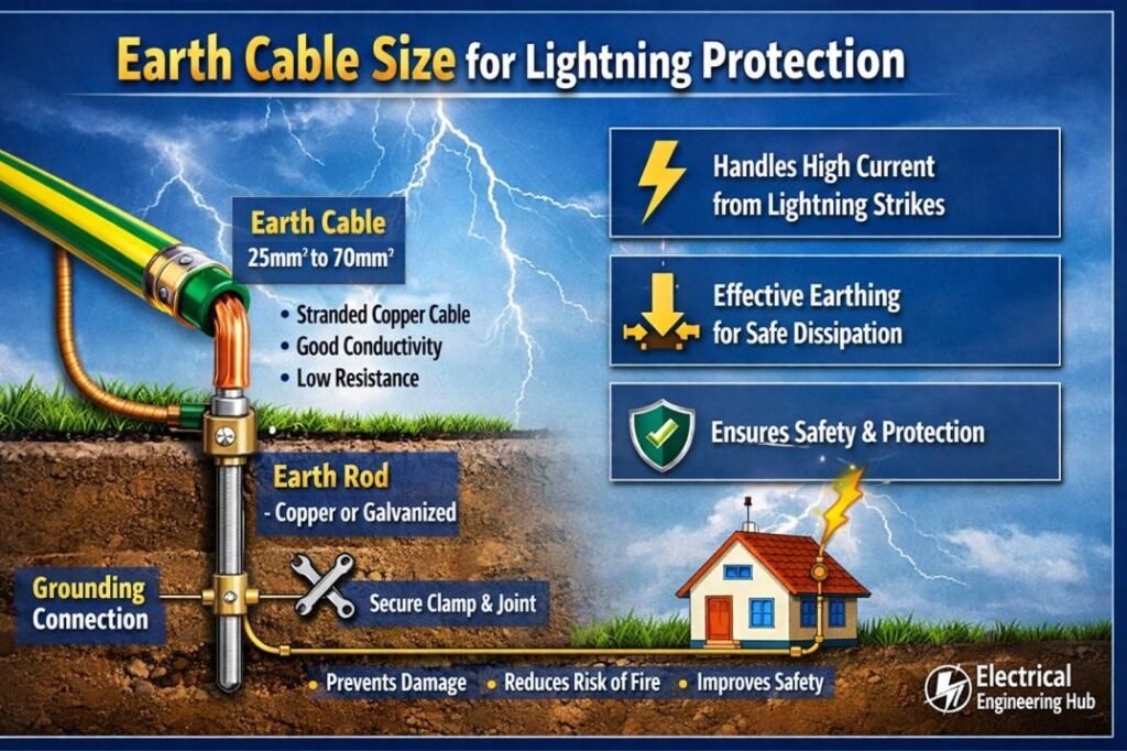
Table of Contents
Table of Contents
What Is the Earth Cable Size for Lightning Protection?
The Earth Cable Size for Lightning Protection is selected to carry a high-energy lightning discharge safely from the protected structure to the earth termination system. Unlike an ordinary protective earth conductor, a lightning down conductor must also handle a very fast current impulse.
A common practical starting point is 35 mm² copper for a lightning down conductor. Larger conductors may be required depending on the standard, material, installation method, mechanical requirements, and risk assessment.
For example, a building may use:
- Air terminals on the roof
- Copper or aluminum down conductors
- Equipotential bonding
- Earth electrodes
- Earth inspection pits
- Surge protective devices
- Lightning equipotential bonding
The complete system matters more than cable size alone.
Lightning Arrester Earthing Cable Size
The lightning arrester earthing cable size depends on the type of arrester and the installation. A surge arrester installed on an electrical distribution system should have a short, direct connection to the grounding system.
For low-voltage surge protection, a 16 mm² copper conductor is often used as a practical installation size, while larger conductors such as 25 mm² or 35 mm² may be selected where the installation specification or lightning protection design requires them.
| Equipment | Typical Copper Earth Conductor | Important Consideration |
|---|---|---|
| LV Type 1 SPD | 16–25 mm² | Keep leads short |
| LV Type 2 SPD | 6–16 mm² | Follow SPD manufacturer |
| Distribution transformer arrester | 25–35 mm²+ | High-energy discharge |
| MV surge arrester | 25–50 mm²+ | Project/utility standard |
| Solar DC SPD | 6–16 mm² | Minimize loop length |
| Lightning protection down conductor | 35 mm² typical | Dedicated down path |
Always check the manufacturer’s specified grounding conductor and the governing installation standard.
If you are selecting conductors for a wider range of electrical installations, our Earthing Cable Size Standard guide compares IEC, NEC, BS 7671, and IEEE 80 requirements to help you choose the appropriate conductor size.
Down Conductor Size for Lightning Protection
Selecting the correct down conductor size for lightning protection is essential for safely carrying lightning current from the air terminal to the grounding electrode system. For typical building lightning protection systems, copper, aluminum, and galvanized steel conductors are commonly selected according to the applicable lightning protection standard, installation environment, and mechanical requirements.
| Conductor Material | Common Minimum Cross-Section | Approx. AWG | Typical Use |
|---|---|---|---|
| Copper | 16 mm² | 5 AWG | Lightning down conductor |
| Aluminum | 25 mm² | 3 AWG | Lightning protection systems |
| Galvanized Steel | 50 mm² | 1/0 AWG | Structural/mechanical applications |
| Copper Tape | 25 × 3 mm | ≈ 2 AWG equivalent | Building down conductors |
| Aluminum Tape | 25 × 3 mm | ≈ 3 AWG equivalent | External LPS |
Down Conductor Size Chart
| Copper Size | Approx. AWG | Aluminum Size | Approx. AWG |
|---|---|---|---|
| 16 mm² | 5 AWG | 25 mm² | 3 AWG |
| 25 mm² | 3 AWG | 35 mm² | 2 AWG |
| 35 mm² | 2 AWG | 50 mm² | 1/0 AWG |
| 50 mm² | 1/0 AWG | 70 mm² | 2/0 AWG |
| 70 mm² | 2/0 AWG | 95 mm² | 3/0 AWG |
The required conductor should also have adequate mechanical strength, corrosion resistance, and a direct, low-impedance route to the grounding system. Avoid sharp bends and unnecessary loops because lightning current contains very high-frequency components.
When determining the Earth Cable Size for Lightning Protection, coordinate the down conductor, bonding connections, earth electrode, and equipotential bonding system as one complete lightning protection system.
Important: Actual minimum sizes depend on the governing standard and system design. IEC 62305, NFPA 780, UL 96A, or local electrical codes may specify different conductor dimensions, so the applicable standard should always be checked before installation.
Why Lightning Earthing Requires More Than a Large Cable
It is easy to assume that increasing cable size automatically makes a lightning protection system safer. In practice, conductor routing can be just as important.
Lightning has a very fast rise time. The inductive voltage developed along a long or badly routed conductor can become significant even when the conductor has a large cross-sectional area.
For effective lightning grounding:
- Keep down conductors as straight as practical.
- Avoid unnecessary loops.
- Minimize sharp bends.
- Use secure mechanical and electrical connections.
- Keep SPD grounding conductors short.
- Provide proper bonding between metallic systems.
- Use suitable earth electrodes.
- Protect exposed conductors from mechanical damage.
A short, straight 35 mm² conductor can perform better in a lightning installation than a much larger conductor installed with unnecessary loops and bends.
Copper vs Aluminum vs Galvanized Steel
Material selection affects conductivity, corrosion resistance, mechanical strength, and compatibility with other metals.
| Material | Relative Conductivity | Advantages | Limitations |
|---|---|---|---|
| Copper | Excellent | High conductivity, durable | Higher cost |
| Aluminum | Good | Lightweight, economical | Corrosion/compatibility concerns |
| Galvanized steel | Lower | Strong and economical | Higher resistance than copper |
| Stainless steel | Moderate | Excellent corrosion resistance | Higher cost |
Copper is widely preferred where space is limited and low impedance is important. Aluminum can be useful for external down conductors, but it should not be placed directly against certain masonry or underground materials without suitable protection.
Galvanic corrosion must also be considered when connecting dissimilar metals.
Lightning Protection Conductor Size by Standard
Different standards use different terminology and sizing methods. Therefore, there is no single global cable size that applies to every lightning protection system.
| Standard | Main Area | General Approach |
|---|---|---|
| IEC 62305 | Lightning protection | LPS design, conductor dimensions and protection zones |
| NFPA 780 | Lightning protection | Requirements for lightning protection systems |
| BS EN 62305 | Lightning protection | UK adoption of IEC 62305 |
| NEC | Electrical installations | Grounding, bonding and surge protection requirements |
| IEEE 80 | Substation grounding | Grounding grid safety and touch/step voltage |
IEC 62305 is particularly important for dedicated lightning protection system design. NEC requirements are more focused on electrical installation grounding and bonding rather than serving as a complete substitute for an LPS design standard.
This distinction is important when determining the lightning arrester earthing cable size for substations, solar plants, buildings, and industrial facilities.
Earth Cable Size for Solar Lightning Protection
Solar PV systems require special attention because the PV array is exposed and often installed across large roof or ground areas.
A typical solar lightning protection arrangement can include:
- PV module frame bonding
- Mounting structure bonding
- DC surge protection
- AC surge protection
- Inverter grounding
- Lightning down conductors
- Earth electrodes
- Equipotential bonding
| Solar System Component | Typical Copper Conductor |
|---|---|
| PV frame bonding | 4–6 mm² |
| Equipment protective earth | Based on fault-current design |
| DC SPD grounding | 6–16 mm² |
| AC SPD grounding | 6–16 mm² |
| Lightning down conductor | 35 mm² typical |
| Main lightning earth connection | 35 mm² or larger |
These values are design starting points rather than universal mandatory sizes. PV installation requirements should be checked against the applicable electrical and lightning protection standards.
For a complete comparison of grounding conductor selection across different standards, see our Earthing Cable Size Standard guide before finalizing your conductor specification.
Lightning Earth Electrode and Ground Resistance
A correctly sized conductor cannot compensate for a poorly designed earth termination system.
The earth electrode system should provide a suitable path for discharge current while keeping dangerous potential differences under control. Depending on soil conditions and the installation, engineers may use:
- Ground rods
- Earth plates
- Ground rings
- Foundation electrodes
- Ground grids
- Multiple interconnected electrodes
Soil resistivity is an important factor. Dry, rocky soil can require a different electrode arrangement from moist, low-resistivity soil.
For large facilities, grounding design should consider touch voltage, step voltage, transferred potential, fault current, and lightning current distribution rather than focusing only on a single earth resistance measurement.
Lightning Protection Earth Resistance Value
For an effective lightning protection system, the lightning protection earth resistance value should be kept as low as practicable to provide a reliable path for lightning current. A commonly used design target is 10 Ω or less, but IEC 62305 does not prescribe a universal maximum earth resistance value; it emphasizes an effective, low-impedance earthing arrangement and equipotential bonding.
NFPA 780 similarly focuses on grounding electrode requirements rather than a single mandatory resistance limit.
| Standard / Guide | Earth Resistance Guidance | Key Point |
|---|---|---|
| IEC 62305 | No universal maximum Ω value | Use a suitable, low-impedance earth termination system |
| NFPA 780 | No single mandatory Ω limit | Grounding electrodes and bonding are specified |
| IEEE Std 80 | Based on touch/step voltage and grid performance | Resistance alone is not the only design criterion |
| Common engineering practice | ≤10 Ω | Frequently adopted project/design target |
| Sensitive installations | ≤5 Ω or lower | May be specified by project requirements |
When selecting an Earth Cable Size for Lightning Protection, do not size the conductor based only on resistance. Conductor cross-section, material, lightning current withstand capability, electrode configuration, soil resistivity, bonding, and applicable local standards must also be considered. A low measured resistance does not by itself guarantee safe lightning protection.
How to Install a Lightning Earthing Cable
The installation route should be planned before the conductor is fixed to the building.
Recommended installation practices
- Route the conductor vertically where possible.
- Avoid sharp 90-degree bends.
- Use smooth-radius bends where changes in direction are unavoidable.
- Keep the conductor away from sensitive internal wiring where practical.
- Use approved clamps and connectors.
- Ensure connections remain accessible for inspection.
- Protect exposed conductors against physical damage.
- Bond relevant metallic services according to the LPS design.
- Connect the down conductor to an appropriately designed earth termination system.
For surge protective devices, the connection should be particularly short. Long SPD earth leads increase inductive voltage during a fast surge.
Lightning Earthing Cable Bend Radius
Bends are an often-overlooked part of lightning protection design. A sharp bend can increase impedance and encourage side-flashing or unwanted voltage differences.
| Installation Feature | Preferred Practice |
|---|---|
| Down conductor route | Straight and vertical |
| Direction change | Smooth radius |
| Sharp 90° bend | Avoid where possible |
| Conductor loop | Avoid |
| SPD earth lead | Keep extremely short |
| Parallel sensitive cables | Maintain suitable separation/bonding |
The exact minimum bend radius should follow the conductor, connector, and lightning protection system manufacturer’s requirements.
Common Earth Cable Sizes in mm² and AWG
AWG is commonly used in North America, while mm² is more common in IEC-based installations.
| Metric Size | Approximate AWG Equivalent |
|---|---|
| 6 mm² | 9 AWG |
| 10 mm² | 8 AWG |
| 16 mm² | 6 AWG |
| 25 mm² | 3 AWG |
| 35 mm² | 2 AWG |
| 50 mm² | 1/0 AWG |
| 70 mm² | 2/0 AWG |
| 95 mm² | 3/0 AWG |
These are approximate cross-sectional equivalents. AWG and metric cable sizes are not exact one-to-one conversions, so use the actual conductor area specified by the applicable standard.
Lightning Protection vs Equipment Earthing
Lightning protection and protective earthing are related but should not be treated as identical systems.
| Feature | Lightning Protection | Protective Earthing |
|---|---|---|
| Main purpose | Conduct lightning current safely | Clear electrical faults |
| Current type | Impulse/high-frequency | Power-frequency fault current |
| Main concern | Low impedance | Fault-current capacity |
| Typical conductor | 35 mm²+ common in LPS | Depends on circuit protection |
| Key design factors | Routing and bonding | Fault current and disconnection |
This is why simply connecting a lightning down conductor to a small equipment grounding wire may not provide an appropriate lightning protection path.
For broader conductor selection, sizing rules, and international standard comparisons, use our Earthing Cable Size Standard reference as a companion to this lightning protection guide.
Lightning Earthing Design Checklist
Before commissioning the system, verify the following:
- Correct conductor material selected
- Conductor cross-sectional area verified
- Down conductor route is as straight as practical
- Sharp bends and loops minimized
- Earth electrodes properly installed
- Connections are mechanically secure
- Corrosion protection provided
- Metallic services bonded where required
- SPDs have short grounding connections
- Earth continuity tested
- Grounding system tested according to the project requirements
- Installation checked against the applicable standard
Related Tools
FAQs
What size cable is used for lightning earthing?
A 35 mm² copper conductor is a common practical starting point for a dedicated lightning down conductor, but the required size depends on the applicable lightning protection standard, conductor material, system class, and installation design.
What is the lightning arrester earthing cable size?
For a lightning or surge arrester, copper conductors in the 16–35 mm² range are commonly encountered. The exact size should follow the arrester manufacturer’s instructions and the applicable electrical or utility standard.
Is 16 mm² copper enough for lightning protection?
It may be suitable for certain surge protection or equipment grounding applications, but it should not automatically be used as the main lightning down conductor. Dedicated LPS conductors often require a larger cross-sectional area and must be selected according to the LPS design.
Can aluminum cable be used for lightning earthing?
Yes, aluminum is used in some external lightning protection systems. However, its use is subject to material compatibility, corrosion, installation location, and the requirements of the applicable standard. Underground applications require particular care.
Does a lower earth resistance guarantee better lightning protection?
No. Low earth resistance is useful, but lightning protection also depends on conductor routing, impedance, bonding, electrode design, connection quality, and control of potential differences. A complete LPS should be designed as a system rather than around one resistance value.
Get new guides in your feed. Follow Electrical Insights on LinkedIn for new electrical standards guides, calculators and design tips from Azad Circuit Hub.
#EarthCableSize, #LightningProtection, #LightningArrester, #EarthingCable, #LightningArresterEarthing, #GroundingSystem, #ElectricalEarthing, #SurgeProtection, #ElectricalSafety, #EarthingDesign
