Earth Cable Size for Solar Panels
Choosing the right earth cable size for solar panels is a critical part of any solar installation. A well-sized earth cable not only protects the system but also ensures safety for users and equipment. This article will guide you through everything you need to know about selecting the proper earthing cable, technical insights, standards, and calculation methods to help you make informed decisions.
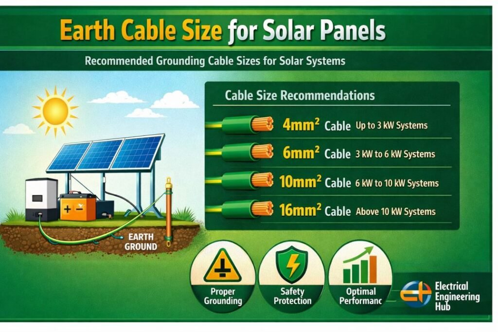
Table of Contents
Table of Contents
Importance of Earth Cable Size for Solar Panels
In a solar panel system, the earthing cable connects the metallic parts of the system to the ground. It provides a low-resistance path for fault current. This helps in protecting both humans and equipment from electrical shock and fire hazards. Undersized earth cables can overheat, fail to clear faults, or even become a fire risk. That is why choosing the correct earth cable size for solar panels is non-negotiable.
For detailed Calculation explore our guide on Earthing Cable Size as Per IEC 60364-5-54
Factors That Affect Earth Cable Size for Solar Panels
There are several key factors that influence the choice of earth cable:
- Fault current level
- Length of the cable
- Type of soil (resistivity)
- System voltage
- Type of installation (surface or buried)
Need to verify the correct grounding conductor for your complete electrical installation, not just solar panels?
Use our Earth Conductor Size Calculation guide to calculate compliant earth conductor sizes for residential, commercial, and industrial systems.
Earth Cable Sizes for Solar Installations
The table below shows typical sizes used in residential and commercial solar panel installations.
| Solar System Size | Fault Current (A) | Recommended Earth Cable Size (Copper, mm²) |
|---|---|---|
| Up to 1 kW | 30 A | 2.5 mm² |
| 1–3 kW | 40 A | 4 mm² |
| 3–5 kW | 50 A | 6 mm² |
| 5–10 kW | 70 A | 10 mm² |
| Above 10 kW | 100 A and above | 16 mm² or more |
Solar Earthing Wire Size
Selecting the correct solar earthing wire size is essential for protecting PV modules, mounting structures, inverters, and people from fault currents and lightning-related surges. Most residential rooftop solar systems use a copper grounding conductor sized according to local electrical codes (such as NEC Article 250 or IEC standards). The exact size depends on system capacity, conductor material, and overcurrent protection.
| Solar System Size | Recommended Copper Earthing Wire* | Typical Application |
|---|---|---|
| Up to 5 kW | 6 mm² (≈10 AWG) | Residential rooftop systems |
| 5–15 kW | 10 mm² (≈8 AWG) | Large homes & small commercial |
| Above 15 kW | 16 mm² or larger | Commercial & industrial PV |
*Always verify the final solar earthing wire size with your local electrical code and the inverter manufacturer’s installation requirements. For large solar farms or lightning-prone locations, engineering calculations may require a larger grounding conductor.
Choosing the right grounding conductor is essential for solar safety. See our complete Earthing Cable Size Standard guide for practical sizing references and standards.
Solar Earthing Wire Size in mm
Choosing the correct solar earthing wire size is important for safely carrying fault current and reducing shock and equipment-damage risks. For most rooftop solar installations, copper or appropriately sized aluminum grounding conductors are selected based on the applicable electrical code, inverter instructions, fault current, and installation method.
| Solar System Size | Typical Copper Earth Wire | Approx. Metric Size | Typical Application |
|---|---|---|---|
| Up to 3 kW | 4 mm² | 4 mm | Small residential PV |
| 3–5 kW | 6 mm² | 6 mm | Residential rooftop |
| 5–10 kW | 10 mm² | 10 mm | Larger residential PV |
| 10–20 kW | 16 mm² | 16 mm | Commercial/small industrial |
| 20–50 kW | 25 mm² | 25 mm | Commercial PV |
| 50–100 kW | 35–50 mm² | 35–50 mm | Larger commercial systems |
These values are typical reference ranges, not universal code requirements. The final solar earthing wire size should be verified using the applicable NEC, IEC, BS 7671, or local standard. PV module frames, mounting structures, inverter enclosures, DC equipment, and AC equipment should be bonded into the protective earthing system as required. Always consider conductor material, fault-current capacity, mechanical protection, corrosion, and the manufacturer’s installation instructions.
How Many Earthing Required for Solar System?
The number of earthing points depends on the solar PV system size, local electrical code, and equipment installed. Most residential systems require separate grounding for the PV module structure, inverter, and lightning protection (where applicable). In many installations, these grounding points are bonded together and connected to a common earth electrode system to maintain equipotential bonding and improve safety.
| Solar System Component | Earthing Required | Purpose |
|---|---|---|
| Solar Panel Structure | Yes | Prevents electric shock and static buildup |
| Solar Inverter | Yes | Protects equipment from fault currents |
| Lightning Protection (if installed) | Yes | Safely dissipates lightning energy |
| Battery Bank (Off-Grid/Hybrid) | As per manufacturer/code | Improves system safety and fault protection |
Proper earthing works together with the correct Earth Cable Size for Solar Panels, ensuring fault currents flow safely to ground while protecting people, equipment, and the entire PV installation.
Solar grounding is only one part of a safe earthing system.
Explore our Earth Conductor Size Calculation resource to determine the correct earth conductor size based on fault current, material, and applicable standards.
Panel to Panel Earthing Wire
A panel to panel earthing wire connects the metal frames of adjacent solar panels to create a continuous grounding path. It helps reduce touch-voltage risk and provides a low-impedance path for fault current, especially when panels use anodized aluminum frames.
| Solar Panel Installation | Typical Earthing Conductor | Common Use |
|---|---|---|
| Residential rooftop | 4 mm² Cu | Small PV arrays |
| Small commercial system | 4–6 mm² Cu | Multiple panels/strings |
| Large commercial array | 6–16 mm² Cu | Longer bonding paths |
| Panel frame bonding | 4 mm² Cu | Panel-to-panel connection |
| Main PV grounding conductor | As per design/code | Array-to-earth connection |
For panel-to-panel bonding, use a green/yellow insulated copper conductor or another conductor permitted by the applicable electrical code. Use listed grounding clips, lugs, washers, and bonding hardware that are compatible with the panel frame. Do not rely on ordinary mounting bolts unless the manufacturer specifically approves them for bonding.
The required conductor size should ultimately be selected according to the applicable code, fault-current withstand requirements, installation method, and manufacturer instructions. For more detailed sizing guidance, see the Earth Cable Size for Solar Panels requirements for the complete PV grounding system.
Copper Clad Grounding Conductor Selection for Solar Power Plants
Proper copper clad grounding conductor selection for solar power plants depends on fault current, conductor length, installation method, soil conditions, and the applicable electrical standard. Copper-clad copper (CCC) combines a copper exterior with a steel core, providing good corrosion resistance and mechanical strength for grounding electrodes and buried conductors.
| Conductor Size | Approx. AWG | Typical Solar Grounding Use |
|---|---|---|
| 4 mm² | 12 AWG | Small PV equipment bonding |
| 6 mm² | 10 AWG | Module/inverter bonding |
| 10 mm² | 8 AWG | Equipment grounding |
| 16 mm² | 6 AWG | PV array grounding |
| 25 mm² | 4 AWG | Larger inverter/array grounding |
| 35 mm² | 2 AWG | Main grounding connections |
| 50 mm² | 1/0 AWG | Plant grounding grid |
| 70 mm² | 2/0 AWG | High fault-current applications |
| 95 mm² | 4/0 AWG | Main grid or substation grounding |
Selection Factors
| Factor | What to Check |
|---|---|
| Fault current | Size for the prospective earth-fault current and clearing time |
| Mechanical strength | Consider buried routes, rocky soil, and installation damage |
| Corrosion | Verify compatibility with soil and grounding electrodes |
| Voltage drop | Usually secondary, but relevant on long bonding paths |
| Standard | Check NEC, IEC, IEEE 80, and local requirements |
For a reliable Earth Cable Size for Solar Panels, do not select the conductor from PV system voltage alone. Final sizing should be verified against the fault-current withstand requirement and the governing electrical code.
Earthing Cable Material and Type
The most common material used is copper due to its low resistivity and high current-carrying capacity. Aluminum is also used, especially in cost-sensitive projects, but it requires larger sizes for the same performance.
Cable types often used include:
- Single-core PVC-insulated copper cable
- XLPE-insulated cable for higher durability
- Bare copper conductor for earth mesh installations
Earth Cable Routing in Solar Systems
The routing of the earth cable should be as short and straight as possible. Sharp bends should be avoided. If the cable is buried, it must be adequately protected against mechanical damage and corrosion. Surface-mounted cables should be UV-resistant.
Size of Earth Wire for Domestic Wiring in SWG
In domestic systems, wire size is sometimes specified using the Standard Wire Gauge (SWG). For example:
| SWG | Diameter (mm) | Approx. Cross-Section (mm²) |
|---|---|---|
| 14 | 2.032 mm | 3.3 mm² |
| 12 | 2.642 mm | 5.5 mm² |
| 10 | 3.251 mm | 8.3 mm² |
Earth Cable Size for DC and AC Side
In solar panel systems, earthing is done separately on the DC side and AC side. On the DC side, earthing connects solar panel frames and mounting structures. On the AC side, the inverter and distribution box are earthed. The cable size may vary depending on the side and application.
For the DC side, the typical cable size is 4 mm² to 6 mm². For the AC side, especially in larger systems, 10 mm² to 16 mm² is commonly used.
Grounding Resistance and Soil Conditions
Grounding resistance should be less than 5 ohms for effective earthing. Soil type plays a big role. Sandy soil has higher resistance than clay or moist soil. In difficult conditions, chemical earthing or earthing enhancement materials may be required.
Measure the ground resistance to verify whether your earth cable size for solar panels is adequate. If not, consider larger cables or parallel earth paths.
Earth Cable Size and Inverter Protection
Inverters are sensitive equipment. Proper earthing protects them from indirect lightning strikes, static charges, and insulation faults. Many inverter manufacturers specify minimum earth cable sizes. Always follow manufacturer recommendations alongside Earthing Cable Size as Per IEC guidelines.
Choosing the right earth cable improves both safety and code compliance across your entire electrical system.
Check our detailed Earth Conductor Size Calculation guide for step-by-step sizing methods, formulas, and practical examples.
Common Mistakes in Earth Cable Selection
Some common errors include:
- Using undersized cable to save cost
- Ignoring soil resistivity
- Using aluminum cables without adjusting for size
- Not bonding all metal parts correctly
These mistakes can lead to dangerous installations. It’s always better to refer to standards and use calculation tools.
Maintenance and Testing
After installation, regular testing of the earthing system is important. Test the ground resistance every year. Look for signs of corrosion or damage to the cable. Proper maintenance ensures the earth cable size for solar panels continues to serve its purpose for years.
Conclusion
Selecting the correct earth cable size for solar panels is a foundational step in building a safe, durable, and efficient solar power system. While it may seem minor compared to panels and inverters, an improperly sized earth cable can result in serious hazards.
Not sure which earth cable size meets electrical standards? Explore our detailed Earthing Cable Size Standard guide for solar and other electrical installations.
Follow Us on Social:
Subscribe our Newsletter on Electrical Insights for latest updates from Electrical Engineering Hub
#SolarPanelWiring, #EarthCableSize, #SolarCableGuide, #GroundingSolarPanels, #SolarInstallation, #RenewableEnergy, #SolarPowerSafety, #ElectricalGrounding, #PVSystemCabling, #SolarTechTips, #GreenEnergy, #OffGridSolar, #SolarSetup, #ElectricalSafety, #SolarPanelSystem