The Complete Guide to Test Equipment & Diagnostics (USA)
The Guide to Test Equipment helps homeowners, automotive technicians, electricians, maintenance teams, and electronics hobbyists choose the right tools to diagnose electrical problems safely. From checking a dead outlet to finding a failing motor winding, the right test equipment can save time, prevent equipment damage, and help identify faults before they become serious.
In the United States, electrical testing often involves 120V and 240V residential circuits, 120/208V commercial systems, 277/480V industrial equipment, and 12V or 48V automotive and battery systems. Each application requires the right instrument, measurement range, and safety procedure.
This guide covers the main electrical testing instruments, practical diagnostic methods, measurement formulas, and selection criteria used in American homes, garages, workshops, and industrial facilities.
Electrical Test Equipment: Quick Reference Chart
Use this table to identify the right instrument for a specific diagnostic task.
| Test Equipment | Main Purpose | Typical Application | Key Feature |
|---|---|---|---|
| Digital multimeter (DMM) | Measures voltage, resistance, and current | Home electrical and automotive work | Multiple measurement functions |
| Clamp meter | Measures current without disconnecting a conductor | Motors, panels, and HVAC systems | Current measurement around one conductor |
| Non-contact voltage tester | Detects a possible AC voltage source | Switches, outlets, and wiring | Quick preliminary screening |
| Receptacle tester | Checks common outlet wiring faults | US three-prong outlets | Identifies certain wiring errors |
| Oscilloscope | Displays electrical signals over time | Electronics and control circuits | Waveform analysis |
| Insulation resistance tester | Measures insulation resistance using DC test voltage | Motors, cables, and electrical equipment | Detects insulation deterioration |
| Circuit breaker finder | Locates the breaker serving a circuit | Residential distribution panels | Helps identify circuit assignments |
| Thermal imaging camera | Displays surface temperature patterns | Panels, connections, and motors | Finds abnormal heating patterns |
| Continuity tester | Checks whether a conductive path exists | Cords, fuses, and disconnected wiring | Open-circuit detection |
| Capacitor tester | Measures capacitance | HVAC motors and electronic equipment | Capacitance in µF or nF |
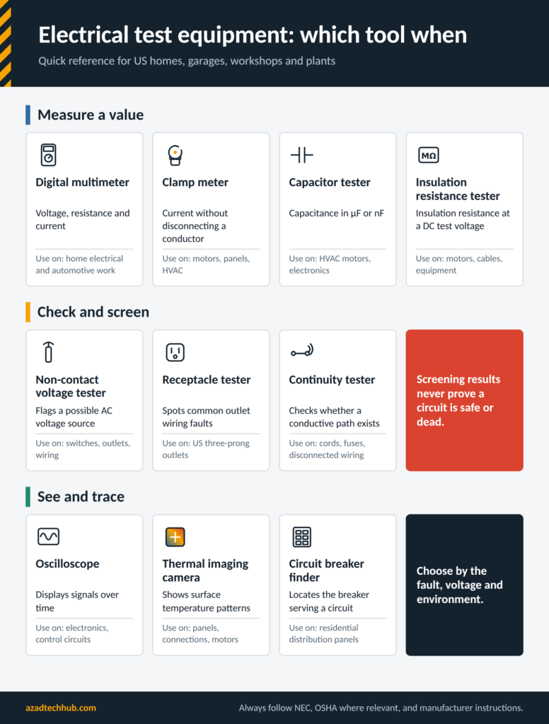
Instrument selection depends on the task, voltage, environment, and required accuracy. A basic multimeter cannot replace every specialized tester, and a simple outlet tester cannot verify every aspect of a receptacle installation.
How to Choose the Right Electrical Test Instrument
Before buying a tester, define the fault you need to find. A tool that works well for checking a car battery may not be suitable for diagnosing a commercial motor control panel.
Consider these factors when comparing electrical test equipment in the USA.
| Selection Factor | What to Check | Why It Matters |
|---|---|---|
| Voltage rating | Maximum AC and DC voltage | Prevents use beyond the instrument’s limits |
| Measurement category | CAT II, CAT III, or CAT IV as applicable | Indicates suitability for defined electrical environments |
| Accuracy | Percentage of reading and digits | Determines measurement confidence |
| Input protection | Fuses, input ratings, and overload protection | Reduces the risk from measurement faults |
| True RMS | Whether the meter measures distorted AC accurately | Useful with variable-frequency drives and electronic loads |
| Display | Resolution, backlight, and polarity indication | Helps with field measurements |
| Leads and probes | Insulation, ratings, and exposed metal length | Affects measurement safety |
| Environment | Dust, moisture, temperature, and impact rating | Matters in garages and industrial areas |
For professional work, check the manufacturer’s specifications rather than relying on a product’s maximum voltage alone. A meter marked 600V is not automatically suitable for every 600V measurement environment.
Understand CAT Safety Ratings
Measurement category ratings help indicate the type of electrical environment for which an instrument is designed.
| Category | General Application |
|---|---|
| CAT II | Loads connected to receptacle-level circuits and similar equipment |
| CAT III | Building distribution, fixed installations, and distribution panels within the rating |
| CAT IV | The origin of a low-voltage installation and certain utility-side measurement locations |
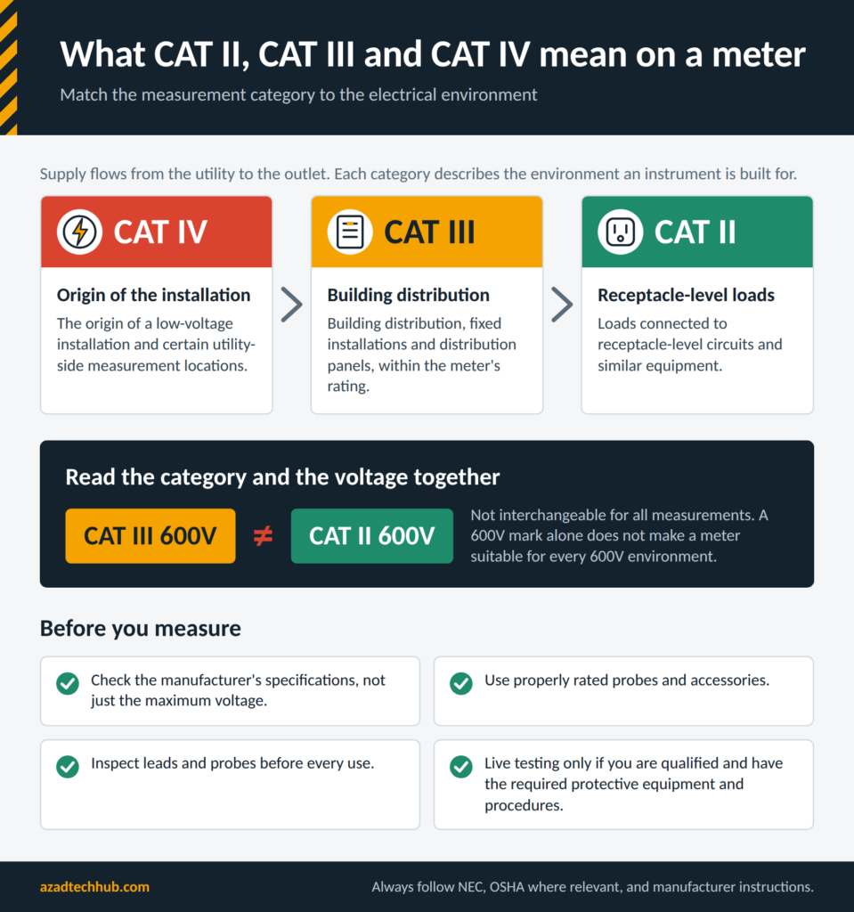
The voltage rating and CAT category must be considered together. For example, a CAT III 600V instrument is not interchangeable with a CAT II 600V instrument for all measurements.
Use properly rated probes and accessories, inspect them before use, and follow the manufacturer’s instructions. Never perform live electrical testing unless you are qualified and have the required protective equipment and procedures.
Digital Multimeter for Automotive Electrical Diagnosis
A digital multimeter is one of the most useful instruments for diagnosing electrical problems in cars, trucks, and light commercial vehicles. It can measure battery voltage, charging-system output, voltage drop, resistance, and continuity in disconnected circuits.
For automotive troubleshooting, look for a meter with DC voltage, resistance, continuity, diode testing, fused current inputs, and suitable input protection. A min/max function can help capture intermittent voltage changes.
Practical Automotive Battery Test
Follow these steps to check a conventional 12V lead-acid battery.
- Park the vehicle, switch off the ignition, and turn off electrical accessories.
- Set the meter to DC volts, using a range above 15V if the meter is not auto-ranging.
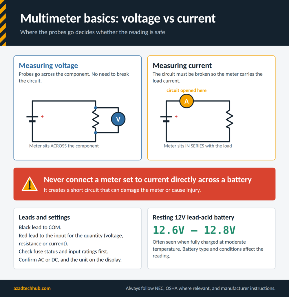
- Connect the red probe to the positive battery terminal and the black probe to the negative terminal.
- Read the voltage after the battery has rested.
- Compare the reading with the battery manufacturer’s guidance and account for battery temperature and state of charge.
A fully charged conventional lead-acid battery often reads around 12.6V to 12.8V at moderate temperature after resting, although battery type and conditions affect the reading.
For a voltage-drop test, measure directly across the cable or connection while the relevant circuit is operating. A large voltage drop can indicate corrosion, a loose connection, or a damaged conductor.
The Guide to Test Equipment should also account for the difference between voltage and current testing. Never place a multimeter set to current directly across a battery. Doing so creates a short circuit and can damage the meter or cause injury.
For a dedicated buying guide, see best multimeter for automotive electrical troubleshooting under $100.
Testing Capacitors in HVAC and Electronic Equipment
Capacitors are used in HVAC motors, fans, pumps, power supplies, and many electronic circuits. A failed capacitor can cause a motor to struggle to start, run poorly, or stop operating.
A capacitance-capable multimeter can help determine whether a capacitor remains within its marked tolerance.
How to Measure Capacitance
- Disconnect the equipment from its power source.
- Follow the manufacturer’s procedure to discharge the capacitor safely using an appropriate method and rated equipment.
- Verify that hazardous voltage is absent with a suitable meter.
- Photograph or label the wiring before disconnecting the capacitor.
- Isolate at least one terminal to avoid measuring parallel circuit components.
- Set the meter to capacitance mode.
- Connect the probes to the capacitor terminals and allow the reading to stabilize.
- Compare the result with the printed capacitance value and tolerance.
For a capacitor marked 40 µF ±5%, the acceptable nominal range is:
Lower limit = 40 × (1 − 0.05) = 38 µF
Upper limit = 40 × (1 + 0.05) = 42 µF
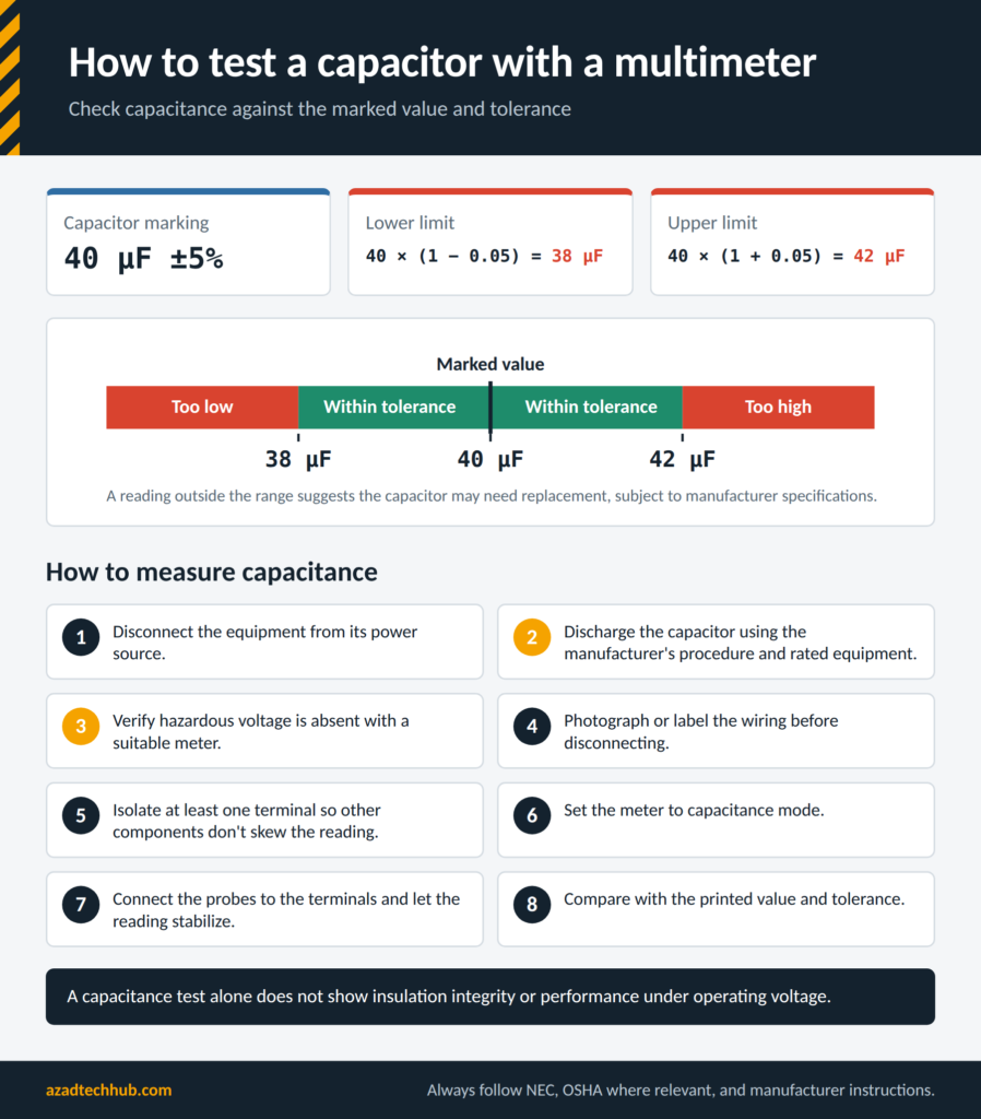
A reading outside this range suggests the capacitor may need replacement, subject to the manufacturer’s specifications. A capacitance test alone does not establish insulation integrity or performance under operating voltage.
Clamp Meter or Multimeter for Residential Electrical Work
A clamp meter is useful when measuring current in a circuit without opening the conductor. A standard multimeter usually measures current through a series connection, which requires breaking the circuit and connecting the meter correctly.
| Feature | Clamp Meter | Digital Multimeter |
|---|---|---|
| AC current | Available on many models | Available within input and fuse limits |
| DC current | Available on selected models | Available on many models |
| Voltage | Available on most models | Available |
| Resistance | Available on many models | Available |
| Circuit interruption | Usually not needed for clamp current measurement | Often required for current measurement |
| Best use | Load current and motor diagnostics | Detailed voltage, resistance, and continuity tests |
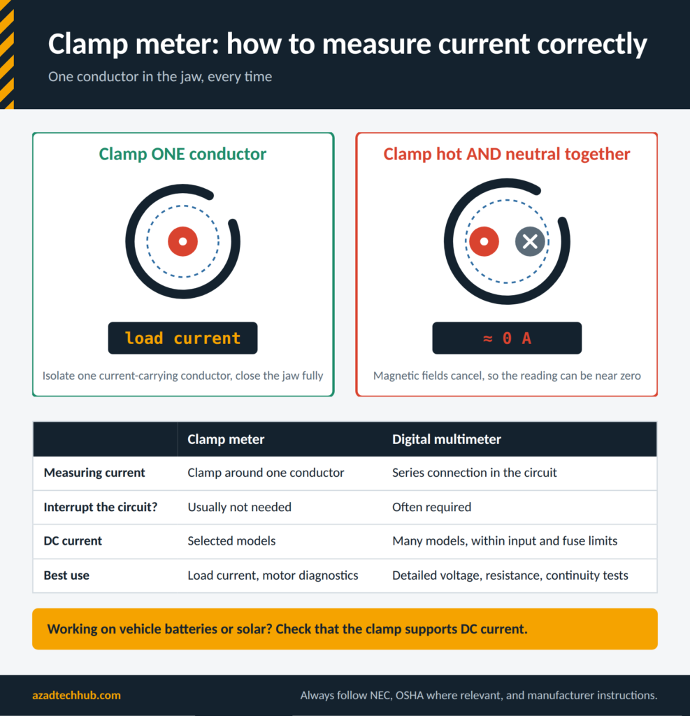
To measure current with a clamp meter, isolate one current-carrying conductor from other conductors, select the appropriate AC or DC current mode, and close the jaw fully around that conductor. Clamping around both the outgoing and return conductors of a normal single-phase circuit may produce a reading near zero because their magnetic fields cancel.
For residential work, a clamp meter with voltage, continuity, and resistance functions offers useful versatility. Check whether the model supports DC current if you work on vehicle batteries or solar systems.
Detecting AC Voltage Before Electrical Work
A non-contact voltage tester can provide a quick indication that an AC voltage source may be present near a wire, switch, or receptacle. These testers are useful for preliminary checks, but they do not prove that a conductor is de-energized.
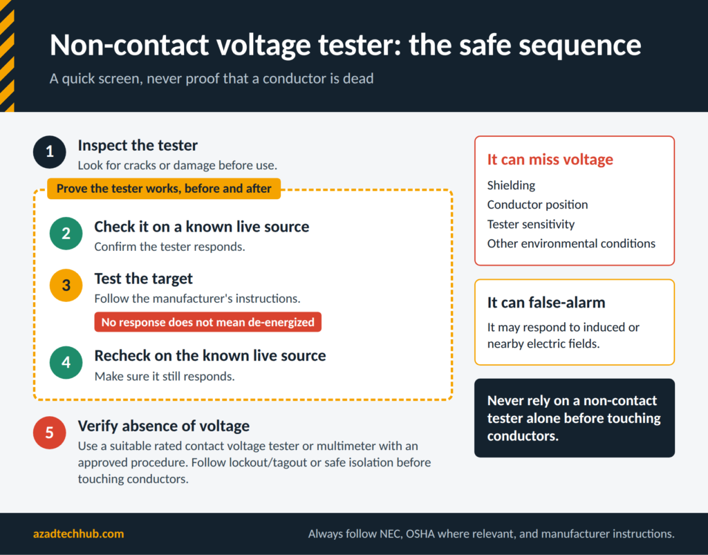
Safe Testing Procedure
- Inspect the tester for cracks or damage.
- Confirm that the tester operates on a known live source.
- Test the target area according to the manufacturer’s instructions.
- Recheck the tester on the known live source afterward.
- If electrical work is planned, use an appropriately rated contact voltage tester or multimeter to verify absence of voltage using an approved procedure.
A non-contact tester may miss voltage because of shielding, conductor position, tester sensitivity, or other environmental conditions. It can also respond to induced or nearby electric fields.
Never rely on a non-contact tester alone before touching conductors. Follow the applicable lockout/tagout or safe isolation procedure for the work involved.
Checking GFCI Receptacles and Ground-Fault Protection
Ground-fault circuit interrupter (GFCI) receptacles are common in locations where electrical shock protection is especially important, including bathrooms, kitchens, garages, and outdoor areas where required by applicable code.
A GFCI monitors current imbalance between the circuit’s current-carrying conductors and trips when its operating conditions are met. It does not replace proper grounding or overcurrent protection.
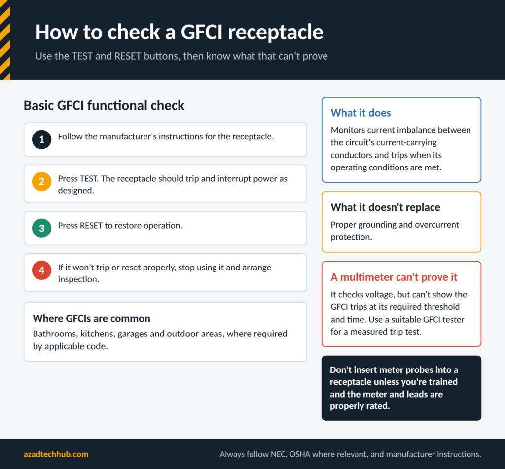
Basic GFCI Functional Check
- Follow the manufacturer’s instructions for the receptacle.
- Press the TEST button. The receptacle should trip and interrupt power as designed.
- Press RESET to restore operation.
- If it does not trip or reset properly, stop using it and arrange appropriate inspection.
A multimeter can check voltage at a receptacle, but it cannot independently prove that the GFCI will trip at its required threshold and within its specified time. Use a suitable GFCI tester or instrument with the appropriate testing function when a measured trip test is required.
Do not insert meter probes into a receptacle unless you are trained to make the measurement safely and the meter and leads are properly rated.
Identifying Outlet Wiring Faults in American Homes
A three-light receptacle tester can identify certain common wiring conditions, including some open-ground, open-neutral, and reversed-polarity faults. It is a useful first check for standard three-prong receptacles.
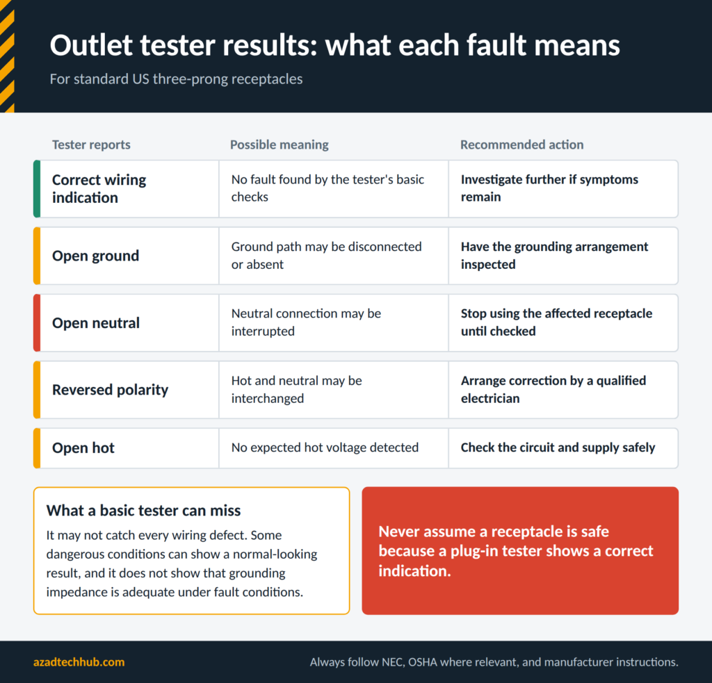
However, a basic tester may not identify every wiring defect. Some dangerous conditions can produce a normal-looking indicator pattern, and these devices do not establish that grounding impedance is adequate under fault conditions.
| Reported Condition | Possible Meaning | Recommended Action |
|---|---|---|
| Correct wiring indication | No fault detected by the tester’s basic checks | Investigate further if symptoms remain |
| Open ground | Ground path may be disconnected or absent | Have the grounding arrangement inspected |
| Open neutral | Neutral connection may be interrupted | Stop using the affected receptacle until checked |
| Reversed polarity | Hot and neutral may be interchanged | Arrange correction by a qualified electrician |
| Open hot | No expected hot voltage detected | Check the circuit and supply safely |
Never assume a receptacle is safe solely because a plug-in tester shows a correct indication. For unexplained faults, use appropriate instruments and qualified inspection.
Reading Multimeter Measurements Correctly
Incorrect meter settings are a common cause of misleading readings and damaged instruments. Before measuring, identify whether the circuit is AC or DC, whether the quantity is voltage or current, and whether the circuit must be energized.
Basic Multimeter Procedure
- Check the meter’s condition, fuse status, and input ratings.
- Insert the black lead into COM.
- Insert the red lead into the correct voltage, resistance, or current input.
- Select the measurement function and range.
- Connect the probes across the component for voltage measurements.
- De-energize and verify the circuit before measuring resistance or continuity.
- Read the display, including units, polarity, and any overload indication.
For example, a reading of 0.25 on a meter displaying volts may mean 0.25V, while a resistance display may show 0.25 kΩ, equivalent to 250 Ω. Always check the displayed unit and range.
For continuity tests, an audible beep usually indicates resistance below the meter’s selected threshold. It does not automatically prove that a conductor can safely carry its rated load.
A meter reading of OL can mean an open circuit or an over-range measurement, depending on the selected function.
Oscilloscopes for Electronics and Control Signal Troubleshooting
An oscilloscope displays voltage as a waveform over time. It can reveal faults that a standard multimeter may miss, including ripple, switching noise, intermittent pulses, timing problems, and distorted control signals.
When selecting a budget oscilloscope, compare bandwidth, sample rate, memory depth, input voltage limits, probe attenuation, and triggering functions.
Basic Oscilloscope Setup
- Confirm the signal’s expected voltage range and frequency.
- Select a probe suitable for the circuit and compensate it according to the manufacturer’s instructions.
- Set the vertical scale to display the expected signal without clipping.
- Set the time base to show several signal cycles.
- Adjust the trigger level to stabilize the waveform.
- Measure amplitude, period, frequency, and any unexpected noise.
Frequency can be calculated from the period:
f = 1 / T
Where:
- f = frequency in hertz (Hz)
- T = period in seconds (s)
For example, if a repeating signal has a period of 0.001 seconds:
f = 1 / 0.001 = 1,000 Hz
Oscilloscope grounding requires special care. The ground clip of a conventional bench oscilloscope may be connected to protective earth. Connecting it to an unsuitable circuit point can create a short circuit. Use an appropriate differential probe or rated isolated instrument when the measurement requires it.
Insulation Resistance Testing for Cables and Motors
Insulation resistance testers, often called megohmmeters or megger testers, apply a specified DC test voltage and measure resistance through insulation. They are used to assess insulation condition in suitable cables, motors, and electrical equipment.
They are not ordinary multimeters. The test voltage can damage connected electronics, surge-protection components, and other sensitive devices.
Safe Insulation Resistance Test
- Identify the equipment and its permitted test voltage.
- Disconnect and isolate the equipment from all power sources.
- Verify absence of voltage with a suitable instrument.
- Disconnect sensitive electronics and components as required by the manufacturer’s instructions.
- Connect the tester to the specified conductors or insulation test points.
- Select the approved test voltage and perform the test according to the relevant procedure.
- Record the resistance, test voltage, duration, and equipment temperature.
- Discharge the equipment after testing as directed by the tester and equipment manufacturer, then verify that it is safe to handle.
For a motor, the appropriate test points and acceptance criteria depend on motor construction, rated voltage, winding connections, and applicable standards. A single universal resistance threshold should not be applied to every motor.
Locating Circuit Breakers and Tracing Branch Circuits
A circuit breaker finder helps identify which breaker supplies a particular receptacle or branch circuit. This is useful when preparing for repairs, updating panel schedules, or checking which rooms share a circuit.
Practical Circuit Tracing Steps
- Confirm that the circuit and receptacle are suitable for the breaker’s finder.
- Connect the transmitter according to the manufacturer’s instructions.
- Scan the panel with the receiver.
- Move the receiver across the breaker rows and compare signal strength.
- Repeat the scan to confirm the likely breaker.
- Verify the circuit by switching the identified breaker off and checking the target receptacle with a suitable tester.
Do not remove panel covers or expose energized busbars merely to use a breaker finder. If the signal is weak or several breakers respond, confirm the result with the manufacturer’s procedure and a safe functional check.
Thermal Imaging for Electrical Panel Inspections
Thermal imaging cameras show temperature patterns across electrical equipment. They can help locate loose connections, overloaded components, phase imbalance, poor ventilation, and abnormal heating.
A thermal camera does not directly measure current, resistance, or internal contact pressure. Its readings can also be affected by emissivity, reflections, airflow, load variation, and viewing angle.
Practical Inspection Procedure
- Confirm that the inspection is permitted under the site’s electrical safety procedure.
- Use a qualified thermographer or electrical professional where energized equipment must be inspected.
- Record the load and operating conditions.
- Scan comparable phases, terminals, breakers, and connections from a safe position.
- Compare similar components under similar loads.
- Document thermal images and any temperature differences.
- Arrange follow-up measurements and corrective work where abnormal heating is found.
A temperature difference between similar components can be more informative than an isolated temperature reading. However, no single temperature threshold applies to every breaker, conductor, or connection.
Testing Extension Cords for Open Circuits and Shorts
Damaged extension cords can cause intermittent operation, overheating, or electric shock. Visual inspection should come first, followed by electrical testing when the cord is disconnected from every power source.
Continuity and Short-Circuit Checks
- Unplug both ends of the cord.
- Inspect the plug, cable jacket, strain relief, and receptacle end for cuts, crushing, burns, or exposed conductors.
- Set a multimeter to continuity or low resistance.
- Test each conductor end to end using an appropriate adapter or accessible contacts.
- Check for unintended continuity between separate conductors while they are isolated.
- Gently flex the cord during testing to look for intermittent opens.
- Replace damaged cords rather than attempting an unsafe repair.
Continuity alone does not establish that the cord can carry its rated current safely. A cord may show continuity but still have damaged strands or a high-resistance connection. Do not perform live tests on exposed or damaged cords.
Common Electrical Measurement Formulas
These formulas help technicians interpret measurements during electrical troubleshooting.
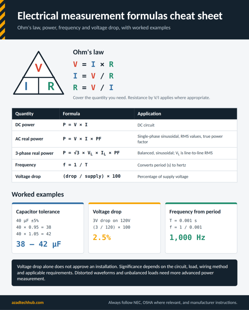
| Quantity | Formula | Application |
|---|---|---|
| Ohm’s law | V = I × R | Relates voltage, current, and resistance |
| Current | I = V / R | Calculates current for a known resistive load |
| Resistance | R = V / I | Calculates resistance from measured voltage and current where appropriate |
| DC power | P = V × I | Calculates power in a DC circuit |
| AC real power | P = V × I × PF | Single-phase sinusoidal systems using RMS values and true power factor |
| Frequency | f = 1 / T | Converts period into frequency |
| Voltage drop percentage | Voltage drop (%) = (Voltage drop / Supply voltage) × 100 | Compares voltage loss with supply voltage |
For example, if a 120V circuit has a measured 3V drop under load:
Voltage drop (%) = (3 / 120) × 100 = 2.5%
The significance of this result depends on the circuit, load, wiring method, and applicable requirements. Do not use this calculation alone to approve an installation.
For balanced three-phase sinusoidal systems, real power can be calculated as:
P = √3 × V_L × I_L × PF
Where V_L is line-to-line RMS voltage, I_L is line current, and PF is the true power factor under the applicable measurement conditions. Distorted waveforms and unbalanced loads may require more advanced power measurements.
Frequently Asked Questions
1. What is the best electrical tester for home use?
A quality digital multimeter is a versatile starting point for checking voltage, resistance, continuity, batteries, and many basic electrical faults. A non-contact voltage tester and a suitable receptacle tester can provide additional screening functions. Choose instruments with appropriate safety ratings, and never rely on a basic tester to prove that wiring is safe.
2. What is the difference between a multimeter and a clamp meter?
A multimeter measures voltage, resistance, and other electrical quantities through probes. A clamp meter measures current by sensing the magnetic field around a conductor, often without disconnecting it. Some clamp meters also provide voltage, resistance, and continuity functions.
3. Can a multimeter detect a bad capacitor?
Yes, if the meter has a suitable capacitance function. Disconnect the capacitor, follow the approved discharge procedure, isolate a terminal where necessary, and compare the reading with the manufacturer’s rated value and tolerance. A capacitance measurement does not detect every possible capacitor failure.
4. What does CAT III mean on a multimeter?
CAT III indicates suitability for specified measurements in building distribution and fixed-installation environments, within the instrument’s voltage and other ratings. It does not mean the meter is safe for every electrical panel or supply system. Both the CAT category and voltage rating must match the application.
5. How often should electrical test equipment be calibrated?
Calibration intervals depend on the instrument, manufacturer’s guidance, usage, environment, required accuracy, and workplace quality procedures. Professional instruments may require scheduled calibration and documented checks. Inspect equipment before use, and verify its performance whenever damage, questionable readings, or other concerns arise.
Final Recommendations
The right test equipment makes electrical troubleshooting more accurate and helps reduce unnecessary component replacement. Start with a suitable digital multimeter, then add specialized instruments according to the work you perform.
In my electrical engineering work, I have found that reliable diagnosis depends on more than obtaining a voltage or resistance reading. It requires checking the instrument setup, understanding the circuit, comparing measurements with equipment specifications, and confirming the suspected fault before replacing parts.
Use the procedures in this Guide to Test Equipment as a starting point for selecting instruments and planning diagnostic checks. Always follow the applicable NEC requirements, OSHA rules where relevant, manufacturer instructions, and site-specific electrical safety procedures. For work involving exposed energized parts or hazardous voltage, use qualified personnel and approved safe-work practices.
Get new guides in your feed. Follow Electrical Insights on LinkedIn for new electrical standards guides, calculators and design tips from Azad Circuit Hub.