
Underground Cable Depth Requirements by Voltage Level (LV/MV/HV/EHV) — IEC/IS Table
Underground cable depth is a key design requirement for safe electrical installations. The correct burial depth protects cables from vehicles, construction work, accidental excavation, ground movement, temperature effects, and mechanical damage. It also provides enough space for sand bedding, protective tiles or slabs, warning tape, and proper cable separation.
There is no single burial depth that applies to every underground power cable. The required depth depends on voltage, installation method, cable construction, location, soil conditions, mechanical protection, and the requirements of the local authority or utility.
For practical design, engineers commonly use deeper trenches as voltage and system importance increase. Low-voltage cables may be installed at relatively shallow depths, while medium-voltage and high-voltage circuits normally require greater protection and more controlled trench construction.
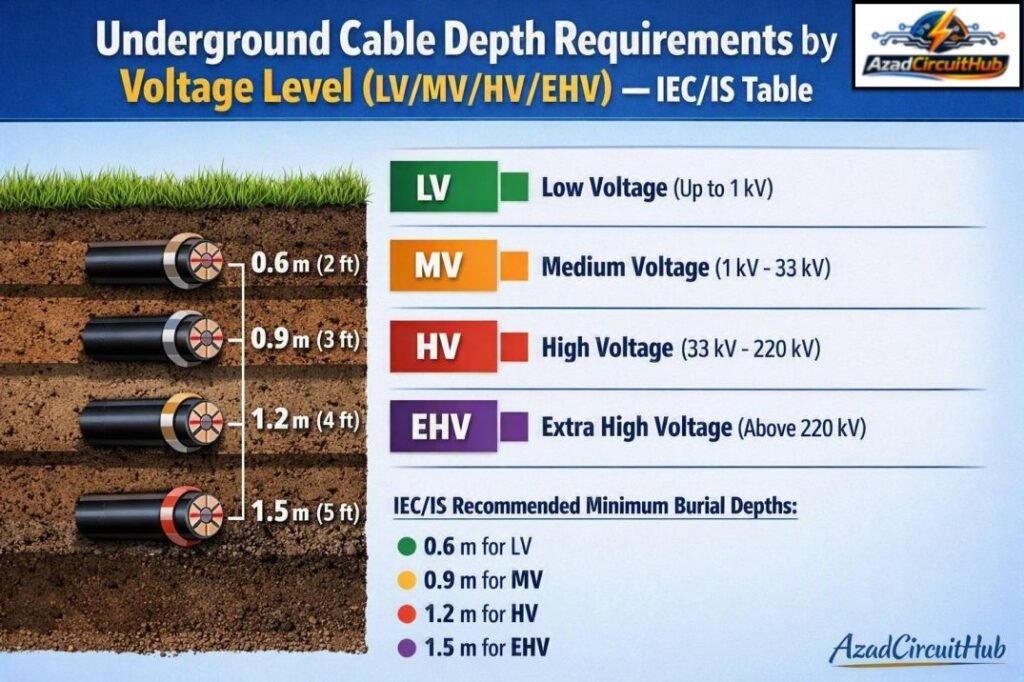
Table of Contents
Table of Contents
Quick Underground Cable Depth Table
The following table provides practical minimum depth ranges commonly used for power cable installation. Always check the applicable project specification, utility standard, and national code before finalizing construction drawings.
| Voltage level | Typical system voltage | Common minimum cover range | Typical application |
|---|---|---|---|
| LV | Up to 1.1 kV | 0.6–0.75 m | Buildings, lighting, distribution |
| MV | 3.3–11 kV | 0.75–1.0 m | Industrial and utility feeders |
| MV | 22–33 kV | 1.0–1.2 m | Distribution networks |
| HV | 66–132 kV | 1.2–1.5 m or project-specific | Subtransmission |
| HV/EHV | 220 kV | 1.5 m or project-specific | Transmission systems |
| EHV | 400–765 kV | Project-specific engineered depth | Major transmission networks |
The values above should be treated as design guidance rather than a universal IEC table. IEC standards generally establish requirements for cable selection, installation, protection, current-carrying capacity, thermal conditions, and electrical safety, while the actual minimum cover is often determined by national standards, utility specifications, road authorities, and project requirements.
Underground Cable Depth by Voltage Level
LV Underground Cable Depth
Low-voltage cables are commonly used at 230/400 V and similar distribution voltages. Typical examples include building feeders, street lighting circuits, residential distribution, commercial installations, and industrial auxiliary supplies.
For a normal underground LV installation, a cover of about 600 to 750 mm is commonly adopted. Where the cable passes beneath roads, parking areas, industrial yards, or locations exposed to heavy vehicles, additional mechanical protection and greater cover may be required.
| LV installation condition | Typical cable cover |
|---|---|
| Normal ground | 600–750 mm |
| Footpath or landscaped area | Around 600 mm or as specified |
| Road crossing | Commonly 750 mm or more |
| Heavy vehicle area | 750–1000 mm, project dependent |
| Cable in protective duct | Depth depends on road/utility requirement |
The important measurement is cable cover, not simply total trench depth. Cover is the vertical distance from the top of the cable, duct, or cable protection system to the finished ground level.
For example, if an LV cable is installed on a 100 mm sand bed and requires 750 mm cover, the excavation must be deeper than 750 mm because space is also needed for bedding and protective layers.
MV Underground Cable Depth
Medium-voltage systems commonly include 3.3 kV, 6.6 kV, 11 kV, 22 kV, and 33 kV networks. Underground MV cables are widely used for industrial plants, substations, utility feeders, solar plants, and large commercial facilities.
A typical MV cable installation uses approximately 750 mm to 1,200 mm of cover, depending on voltage and site conditions.
| MV voltage | Typical cover range | Typical use |
|---|---|---|
| 3.3 kV | 750–900 mm | Industrial distribution |
| 6.6 kV | 750–1000 mm | Motors and plant distribution |
| 11 kV | 750–1000 mm | Utility and industrial feeders |
| 22 kV | 900–1200 mm | Distribution networks |
| 33 kV | 1000–1200 mm | Subtransmission/distribution |
For an 11 kV cable, for example, a project may specify approximately 1.0 m cover in an open area. A road crossing can require additional depth, ducts, concrete protection, or other mechanical protection.
Cable spacing is also important. Single-core MV cables carrying AC should be arranged according to the manufacturer’s recommendations and the required magnetic-field, thermal, and ampacity considerations.
For large MV installations, cable trench design should therefore consider more than burial depth. Cable grouping, spacing, soil thermal resistivity, ambient temperature, sheath bonding, circuit arrangement, and heat dissipation can significantly affect cable ampacity.
If you are designing a cable trench, use our Cable Trench Fill Calculator to check available trench space, cable occupancy, and practical arrangement before finalizing the trench dimensions.
33 kV Underground Cable Depth
33 kV cables deserve particular attention because they are frequently installed between substations, industrial facilities, solar plants, and utility networks.
A cover of approximately 1.0 to 1.2 m is commonly used for 33 kV underground power cables where local specifications permit. Road crossings and areas exposed to mechanical loading may require additional protection.
| Installation | Typical approach |
|---|---|
| Open ground | About 1.0–1.2 m cover |
| Road crossing | Greater depth or duct protection |
| Industrial yard | Depth based on vehicle loading |
| Cable trench | Sand bedding plus protective cover |
| Duct installation | Follow utility and road authority requirements |
The final design should be based on the applicable utility standard rather than selecting depth solely from voltage.
HV Underground Cable Depth
High-voltage underground systems include 66 kV, 110 kV, 132 kV and other subtransmission levels. At these voltages, cable installation becomes more specialized.
Typical HV cable systems may use approximately 1.2 to 1.5 m of cover, although actual project requirements can be higher or lower depending on the cable system and civil design.
HV cables often use XLPE insulation with metallic screens or sheaths. The installation design must consider thermal performance, induced voltages, sheath bonding, fault current, joint bays, link boxes, pulling tension, and minimum bending radius.
| HV voltage | Indicative cover range |
|---|---|
| 66 kV | 1.2–1.5 m |
| 110 kV | 1.2–1.5 m |
| 132 kV | 1.2–1.5 m |
| Above 132 kV | Project-specific |
At HV level, cable depth cannot be selected independently from the cable thermal calculation. Increasing burial depth can sometimes reduce heat dissipation because the cable is surrounded by soil with a particular thermal resistivity.
Therefore, a deeper trench does not automatically mean a better cable installation.
EHV Underground Cable Depth
Extra-high-voltage underground cables are used for major transmission systems, including 220 kV, 400 kV and, in specialized projects, 500 kV, 525 kV and 765 kV systems.
EHV cable systems require project-specific civil, electrical, thermal, and mechanical engineering. A universal burial-depth value should not be assumed.
| EHV level | Typical design approach |
|---|---|
| 220 kV | Engineered trench or duct system |
| 400 kV | Project-specific cable system design |
| 500 kV+ | Highly specialized installation |
| 765 kV | Project-specific engineered installation |
EHV cable routes may include dedicated trenches, ducts, tunnels, cable bridges, special thermal backfill, or other engineered systems. Cable jointing is also a major consideration because long underground transmission circuits require carefully designed joint bays and access arrangements.
IEC 61936-1 is relevant to power installations exceeding 1 kV AC and provides broader requirements for installation safety. For individual cable systems, the applicable IEC cable and installation standards must also be considered.
IEC Standards for Underground Cable Installation
Several IEC standards can be relevant to underground power cable projects. However, they do not all provide one universal minimum burial depth.
| Standard | Main subject | Relevance |
|---|---|---|
| IEC 60364-5-52 | Wiring systems | LV cable installation |
| IEC 60502-1 | Power cables up to 1 kV | LV cable construction |
| IEC 60502-2 | Power cables from 6 kV to 30 kV | MV cable systems |
| IEC 60840 | Power cables above 30 kV up to 150 kV | HV cable systems |
| IEC 62067 | Power cables above 150 kV up to 500 kV | EHV cable systems |
| IEC 61936-1 | Power installations above 1 kV AC | Installation safety and design |
| IEC 60287 | Cable current ratings | Thermal/ampacity calculations |
IEC 60364-5-52 is particularly important for LV installations, while IEC 60502-1 and IEC 60502-2 cover commonly used LV and MV power cables.
For higher voltages, IEC 60840 and IEC 62067 become important depending on the rated voltage and cable system.
The key point is that an IEC cable standard should not be interpreted as a blanket statement that every cable must be buried at a particular depth.
IS Standards for Underground Cable Depth
In India, IS 1255 is one of the important references for installation and maintenance of power cables. It provides guidance for cable laying practices, including underground installation considerations.
| Indian Standard | Subject |
|---|---|
| IS 1255 | Code of practice for installation and maintenance of power cables |
| IS 7098 series | XLPE insulated cables |
| IS 1554 series | PVC insulated heavy-duty electric cables |
| IS 732 | Electrical wiring installations |
| IS/IEC applicable standards | Cable construction and testing |
IS 1255 should be consulted when preparing an Indian cable-laying specification. However, the final burial depth should also account for road crossings, local conditions, utility requirements, cable voltage, mechanical protection, and the project specification.
For projects in Pakistan, engineers should also check the applicable NEPRA requirements, DISCO specifications, NTDC requirements, Pakistan Standards and Quality Control Authority references, road authority requirements, and the project owner’s approved electrical specifications.
Cable Trench Construction and Depth
Cable depth is only one part of a proper underground cable trench. A typical trench may include several layers.
| Trench component | Typical consideration |
|---|---|
| Finished ground level | Reference level for cover |
| Warning tape | Installed above cable/protection |
| Protective tiles/slabs | Used where mechanical protection is required |
| Sand or approved thermal backfill | Protects cable and improves heat transfer |
| Cable | Installed with specified spacing |
| Bedding | Often around 75–100 mm or project specified |
| Bottom of trench | Depends on cable, bedding and cover |
A common arrangement is to provide a sand or approved fine-material bedding below the cable, place the cable with the required spacing, cover it with additional protective material, install warning tape, and then backfill the trench.
The exact dimensions should come from the project specification and cable manufacturer’s installation instructions.
Cable Depth Under Roads and Driveways
Cable routes beneath roads require greater attention because vehicles can impose substantial mechanical loads on the cable system.
A direct-buried cable may require additional cover, reinforced protection, or installation inside a suitable duct. The road authority may specify a minimum depth measured from the finished road surface.
| Location | Recommended design approach |
|---|---|
| Residential ground | Normal utility cover |
| Footpath | Check local authority requirements |
| Driveway | Consider vehicle loading |
| Public road | Follow road authority specification |
| Highway | Duct and engineered crossing often required |
| Railway crossing | Follow railway authority requirements |
Never assume that increasing depth alone makes a road crossing safe. The cable may still need ducting or structural protection.
Cable Depth, Thermal Rating and Soil Conditions
Burial depth affects cable operating temperature and therefore ampacity. Underground cables release heat into surrounding soil. If the soil has poor thermal conductivity, the cable temperature can rise significantly.
Important factors include:
- Soil thermal resistivity
- Soil moisture
- Ambient ground temperature
- Cable spacing
- Number of circuits
- Cable conductor size
- Installation depth
- Duct thermal characteristics
- Backfill material
- Load profile
IEC 60287 provides methods for calculating the current-carrying capacity of cables under defined installation conditions.
For high-load MV and HV circuits, engineers may use thermal backfill with a controlled thermal resistivity. This can provide more predictable heat dissipation than ordinary excavated soil.
Underground Cable Depth vs Trench Depth
These two terms are often confused.
Underground cable depth normally refers to the vertical cover above the cable, while trench depth refers to the total excavation depth.
For example:
| Item | Example dimension |
|---|---|
| Required cable cover | 750 mm |
| Cable diameter | 40 mm |
| Upper protection layer | 100 mm |
| Bottom bedding | 100 mm |
| Approximate excavation depth | About 990 mm |
The actual trench dimensions must be adjusted for cable arrangement, protection, ducts, warning tape, thermal backfill, and site conditions.
Minimum Bend Radius Must Also Be Checked
Cable installation is not complete simply because the correct depth has been achieved. Underground cables must also comply with the manufacturer’s minimum bending radius.
This is particularly important for XLPE, armoured, single-core, and HV cables. Excessive bending can damage insulation, screens, sheaths, or other cable components.
The manufacturer’s installation data should always take priority over a generic bend-radius value.
Underground Cable Separation
Multiple circuits installed in the same trench require suitable separation.
| Installation factor | Why it matters |
|---|---|
| Phase spacing | Thermal and electrical performance |
| Circuit separation | Reduces mutual heating |
| LV/MV separation | Safety and maintenance |
| Power/control separation | Reduces interference and damage risk |
| Communication cables | Prevents unwanted interference |
| Metallic services | Maintains required clearances |
Required separation varies by cable type, voltage, installation arrangement, and applicable standards.
For solar plants and industrial substations, it is especially important to separate MV power circuits from control, communication, and instrumentation cables where required by the project design.
Practical Underground Cable Depth Checklist
Before approving an underground cable route, check the following:
- Confirm the system voltage and cable type.
- Determine the required minimum cover from the governing standard and utility specification.
- Check road, driveway, railway, and crossing requirements.
- Provide suitable cable bedding.
- Check mechanical protection requirements.
- Verify cable spacing and grouping.
- Perform the required cable ampacity calculation.
- Check soil thermal resistivity.
- Confirm minimum bending radius.
- Install warning tape or approved route markers.
- Check separation from other underground services.
- Record the installed route and depth for future excavation work.
A properly designed trench should allow safe installation, heat dissipation, inspection, maintenance, and future identification of the cable route.
If you are calculating trench capacity for multiple power and control cables, check the Cable Trench Fill Calculator before selecting the final trench width and arrangement.
Underground Cable Depth Reference Summary
| Voltage | Typical cover guidance | Main standards/references |
|---|---|---|
| LV up to 1.1 kV | 0.6–0.75 m | IEC 60364-5-52, IEC 60502-1, local codes |
| 3.3–11 kV | 0.75–1.0 m | IEC 60502-2, utility specifications |
| 22–33 kV | 0.9–1.2 m | IEC 60502-2, IS 1255 where applicable |
| 66–132 kV | 1.2–1.5 m | IEC 60840, IEC 61936-1, project specifications |
| 220 kV | Project-specific | IEC 61936-1, IEC 62067 where applicable |
| 400–765 kV | Project-specific | Applicable IEC/utility/project standards |
These figures are useful preliminary design values, but they should not replace the governing standard for a particular project.
Final Takeaway
The correct underground cable depth depends on much more than voltage level. LV cables are often installed with around 600–750 mm of cover, while MV systems commonly use approximately 750–1,200 mm. HV systems may require around 1.2–1.5 m or a project-specific engineered arrangement. EHV cable systems require detailed design rather than relying on a generic burial-depth table.
IEC standards provide the framework for cable construction, installation, thermal performance, and electrical safety, while national standards such as IS 1255 and utility specifications can provide more practical cable-laying requirements. Road crossings, mechanical loading, soil conditions, cable grouping, and thermal performance must always be checked.
For a complete cable trench design, combine the required burial cover with cable spacing, bedding, protection, thermal calculations, and future maintenance requirements. For multiple cables in one trench, use the Cable Trench Fill Calculator to check whether the proposed trench arrangement provides adequate space and practical cable installation clearances.
FAQs
What is the minimum depth for underground electrical cable?
A common minimum cover for LV underground cables is around 600–750 mm, but the actual requirement depends on the installation location and applicable code. Road crossings, heavy traffic areas, and utility projects may require greater depth or mechanical protection.
How deep should an 11 kV underground cable be buried?
An 11 kV cable is commonly installed with about 750–1,000 mm of cover in many installations. The final value should be confirmed against the utility specification, local regulations, cable installation method, and road-crossing requirements.
How deep should a 33 kV cable be buried?
A 33 kV cable commonly uses approximately 1.0–1.2 m of cover in conventional underground installations. The project specification may require greater depth, ducts, protective slabs, or other protection depending on the route.
Does IEC specify a fixed underground cable depth?
IEC standards do not provide one universal burial depth for every underground power cable. Installation requirements depend on the applicable IEC standard, installation conditions, mechanical protection, thermal design, local regulations, and utility specifications.
What is the difference between cable depth and cable cover?
Cable cover is the vertical distance between the top of the cable or protective system and the finished ground level. Trench depth is the total excavation depth, which also includes cable diameter, bedding, protective layers, and other required construction space.
Related Guides
Get new guides in your feed. Follow Electrical Insights on LinkedIn for new electrical standards guides, calculators and design tips from Azad Circuit Hub.
#UndergroundCables, #CableDepth, #CableInstallation, #IECStandards, #ISStandards, #ElectricalEngineering, #LVcables, #MVcables, #HVCables, #EHVCables
